Z97 Extreme9 - Motherboard ASROCK - Free user manual and instructions
Find the device manual for free Z97 Extreme9 ASROCK in PDF.
Download the instructions for your Motherboard in PDF format for free! Find your manual Z97 Extreme9 - ASROCK and take your electronic device back in hand. On this page are published all the documents necessary for the use of your device. Z97 Extreme9 by ASROCK.
USER MANUAL Z97 Extreme9 ASROCK
Version 1.0 Published May 2014 Copyright©2014 ASRock INC. All rights reserved. Copyright Notice: No part of this documentation may be reproduced, transcribed, transmitted, or translated in any language, in any form or by any means, except duplication of documentation by the purchaser for backup purpose, without written consent of ASRock Inc. Products and corporate names appearing in this documentation may or may not be registered trademarks or copyrights of their respective companies, and are used only for identication or explanation and to the owners’ benet, without intent to infringe. Disclaimer: Specications and information contained in this documentation are furnished for informational use only and subject to change without notice, and should not be constructed as a commitment by ASRock. ASRock assumes no responsibility for any errors or omissions that may appear in this documentation. With respect to the contents of this documentation, ASRock does not provide warranty of any kind, either expressed or implied, including but not limited to the implied warranties or conditions of merchantability or tness for a particular purpose. In no event shall ASRock, its directors, ocers, employees, or agents be liable for any indirect, special, incidental, or consequential damages (including damages for loss of prots, loss of business, loss of data, interruption of business and the like), even if ASRock has been advised of the possibility of such damages arising from any defect or error in the documentation or product. is device complies with Part 15 of the FCC Rules. Operation is subject to the following two conditions: (1) this device may not cause harmful interference, and (2) this device must accept any interference received, including interference that may cause undesired operation.
CALIFORNIA, USA ONLY
e Lithium battery adopted on this motherboard contains Perchlorate, a toxic substance controlled in Perchlorate Best Management Practices (BMP) regulations passed by the California Legislature. When you discard the Lithium battery in California, USA, please follow the related regulations in advance. “Perchlorate Material-special handling may apply, see www.dtsc.ca.gov/hazardouswaste/ perchlorate” ASRock Website: http://www.asrock.come terms HDMI™ and HDMI High-Denition Multimedia Interface, and the HDMI logo are trademarks or registered trademarks of HDMI Licensing LLC in the United States and other countries. Manufactured under license under U.S. Patent Nos: 5,956,674; 5,974,380; 6,487,535; 7,003,467 & other U.S. and worldwide patents issued & pending. DTS, the Symbol, & DTS and the Symbol together is a registered trademark & DTS Connect, DTS Interactive, DTS Neo:PC are trademarks of DTS, Inc. Product includes soware. © DTS, Inc., All Rights Reserved.1 English Z97 Extreme9 Motherboard Layout Intel Z97 DDR3_A2 (64 bit, 240-pin module) DDR3_A1 (64 bit, 240-pin module) DDR3_B2 (64 bit, 240-pin module) DDR3_B1 (64 bit, 240-pin module) ATX1 2V1Super I/O
NUT 3NUT 4NUT 5NUT 6
- ere are two LEDs on each LAN port. Please refer to the table below for the LAN port LED indications. Activity / Link LED Speed LED Status Description Status Description Of No Link Of 10Mbps connection Blinking Data Activity Orange 100Mbps connection On Link Green 1Gbps connection ** If you use a 2-channel speaker, please connect the speaker’s plug into “Front Speaker Jack”. See the table below for connection details in accordance with the type of speaker you use. Audio Output Channels Front Speaker (No. 9) Rear Speaker (No. 7) Central / Bass (No. 6) Line In (No. 8) 2 V -- -- -- 4 V V -- -- 6 V V V -- 8 V V V V *** e eSATA connector supports SATA with cables within 1 meters. e SATA3_A4 connector is shared with the eSATA port. To enable Multi-Streaming, you need to connect a front panel audio cable to the front panel audio header. Aer restarting your computer, you will nd the “Mixer” tool on your system. Please select “Mixer ToolBox” , click “Enable playback multi-streaming”, and click “ok”. Choose “2CH”, “4CH”, “6CH”, or “8CH” and then you are allowed to select “Realtek HDA Primary output” to use the Rear Speaker, Central/Bass, and Front Speaker, or select “Realtek HDA Audio 2nd output” to use the front panel audio.
SPEED LED LAN Port6 English 1 Introduction ank you for purchasing ASRock Z97 Extreme9 motherboard, a reliable motherboard produced under ASRock’s consistently stringent quality control. It delivers excellent performance with robust design conforming to ASRock’s commitment to quality and endurance.
1 x I/O Panel Shield
1 x Screw for mini-PCIe Slot Because the motherboard specications and the BIOS soware might be updated, the content of this documentation will be subject to change without notice. In case any modications of this documentation occur, the updated version will be available on ASRock’s website without further notice. If you require technical support related to this motherboard, please visit our website for specic information about the model you are using. You may nd the latest VGA cards and CPU support list on ASRock’s website as well. ASRock website http://www.asrock.com.7 English Z97 Extreme9
High Density Glass Fabric PCB
Multiple Filter Cap (MFC) (Filter dierent noise by 3 dierent capacitors: DIP solid cap, POSCAP and MLCC) CPU
12 Power Phase design
Supports Intel® Turbo Boost 2.0 Technology
Supports Intel® K-Series unlocked CPUs
Supports ASRock BCLK Full-range Overclocking Chipset
Dual Channel DDR3 Memory Technology
Max. capacity of system memory: 32GB (see CAUTION1)
Supports Intel® Extreme Memory Prole (XMP) 1.3 / 1.2
15 Gold Contact in DIMM Slots Expansion Slot
Intel® HD Graphics Built-in Visuals and the VGA outputs can be supported only with processors which are GPU integrated.
Supports Intel® HD Graphics Built-in Visuals : Intel® Quick Sync Video with AVC, MVC (S3D) and MPEG-2 Full HW Encode1, Intel® InTru
Dual graphics output: Support HDMI and DiaplayPort 1.2 ports by independent display controllers
Supports HDMI with max. resolution up to 4K x 2K (4096x2304) @ 24Hz
Supports Auto Lip Sync, Deep Color (12bpc), xvYCC and HBR (High Bit Rate Audio) with HDMI Port (Compliant HDMI monitor is required)
Supports HDCP with HDMI and DisplayPort 1.2 Ports
Supports Full HD 1080p Blu-ray (BD) playback with HDMI and DisplayPort 1.2 Ports Audio
7.1 CH HD Audio with Content Protection (Realtek
Supports Surge Protection (ASRock Full Spike Protection)
Supports Purity Sound
- Nichicon Fine Gold Series Audio Caps - 115dB SNR DAC with Dierential Amplier - TI® NE5532 Premium Headset Amplier (Supports up to 600 Ohms headsets) - Direct Drive Technology - EMI Shielding Cover - PCB Isolate Shielding
Supports DTS Connect9 English Z97 Extreme9 LAN
Supports Intel® Remote Wake Technology (on Intel® I218V)
Supports Wake-On-LAN
Supports Lightning/ESD Protection (ASRock Full Spike Protection)
Supports Dual LAN with Teaming
Supports Energy Ecient Ethernet 802.3az
Supports PXE Rear Panel I/O
4 x USB 2.0 Ports (Supports ESD Protection (ASRock Full Spike Protection))
4 x USB 3.0 Ports (Supports ESD Protection (ASRock Full Spike Protection))
2 x RJ-45 LAN Ports with LED (ACT/LINK LED and SPEED LED)
HD Audio Jacks: Rear Speaker / Central / Bass / Line in / Front Speaker / Microphone Storage
6 x SATA3 6.0 Gb/s Connectors by Intel® Z97, support RAID (RAID 0, RAID 1, RAID 5, RAID 10, Intel Rapid Storage Technology 13 and Intel Smart Response Technology), NCQ, AHCI, Hot Plug and ASRock HDD Saver Technology
4 x SATA3 6.0 Gb/s Connectors by ASMedia ASM1061, support NCQ, AHCI, Hot Plug and ASRock HDD Saver Technology (SATA3_A4 connector is shared with the eSATA port)
2 x SATA Express Connectors (SATAE_2 is shared with SATA3_1 and SATA3_2; SATAE_1 is shared with SATA3_4, SATA3_5 and M.2 Socket (M2_2))
- Support to be announced
1 x eSATA Connector by ASMedia ASM1061, supports NCQ, AHCI and Hot Plug10 English
2 x CPU Fan Connectors (1 x 4-pin, 1 x 3-pin)
3 x Chassis Fan Connectors (1 x 4-pin, 2 x 3-pin)
1 x Power Fan Connector (3-pin)
2 x 8 pin 12V Power Connectors (Hi-Density Power Connec- tor)
1 x Front Panel Audio Connector
1 x underbolt AIC Connector
2 x USB 2.0 Headers (support 4 USB 2.0 ports) (Supports ESD Protection (ASRock Full Spike Protection))
2 x USB 3.0 Headers (Support 4 USB 3.0 ports) (ASMedia ASM1074 hub) (Supports ESD Protection (ASRock Full Spike Protection))
1 x Dr. Debug with LED
1 x Power Switch with LED
1 x Reset Switch with LED
Supports Secure Backup UEFI Technology
ACPI 1.1 Compliant wake up events
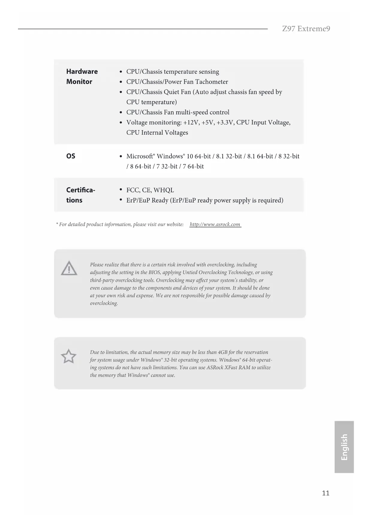
CPU/Chassis temperature sensing
CPU/Chassis Quiet Fan (Auto adjust chassis fan speed by CPU temperature)
CPU/Chassis Fan multi-speed control
ErP/EuP Ready (ErP/EuP ready power supply is required) Please realize that there is a certain risk involved with overclocking, including adjusting the setting in the BIOS, applying Untied Overclocking Technology, or using third-party overclocking tools. Overclocking may aect your system’s stability, or even cause damage to the components and devices of your system. It should be done at your own risk and expense. We are not responsible for possible damage caused by overclocking.
- For detailed product information, please visit our website: http://www.asrock.com Due to limitation, the actual memory size may be less than 4GB for the reservation for system usage under Windows® 32-bit operating systems. Windows® 64-bit operat- ing systems do not have such limitations. You can use ASRock XFast RAM to utilize the memory that Windows® cannot use.12 English is is an ATX form factor motherboard. Before you install the motherboard, study the conguration of your chassis to ensure that the motherboard ts into it. Pre-installation Precautions Take note of the following precautions before you install motherboard components or change any motherboard settings.
Make sure to unplug the power cord before installing or removing the motherboard components. Failure to do so may cause physical injuries and damages to motherboard components.
In order to avoid damage from static electricity to the motherboard’s components, NEVER place your motherboard directly on a carpet. Also remember to use a grounded wrist strap or touch a safety grounded object before you handle the components.
Hold components by the edges and do not touch the ICs.
Whenever you uninstall any components, place them on a grounded anti-static pad or in the bag that comes with the components.
When placing screws to secure the motherboard to the chassis, please do not over- tighten the screws! Doing so may damage the motherboard.
2.1 Installing the CPU
1. Before you insert the 1150-Pin CPU into the socket, please check if the PnP cap
is on the socket, if the CPU surface is unclean, or if there are any bent pins in the socket. Do not force to insert the CPU into the socket if above situation is found. Otherwise, the CPU will be seriously damaged.
English Z97 Extreme9 Please save and replace the cover if the processor is removed. e cover must be placed if you wish to return the motherboard for aer service.16 English
2.2 Installing the CPU Fan and Heatsink
is motherboard provides four 240-pin DDR3 (Double Data Rate 3) DIMM slots, and supports Dual Channel Memory Technology. Dual Channel Memory Conguration e DIMM only ts in one correct orientation. It will cause permanent damage to the motherboard and the DIMM if you force the DIMM into the slot at incorrect orientation. Priority DDR3_A1 DDR3_A2 DDR3_B1 DDR3_B2 1 Populated Populated 2 Populated Populated 3 Populated Populated Populated Populated
1. For dual channel conguration, you always need to install identical (the same
brand, speed, size and chip-type) DDR3 DIMM pairs.
2. It is unable to activate Dual Channel Memory Technology with only one or three
memory module installed.
3. It is not allowed to install a DDR or DDR2 memory module into a DDR3 slot;
otherwise, this motherboard and DIMM may be damaged.18 English
ere are 5 PCI Express slots and 1 mini-PCI Express slot on the motherboard. PCIe slots: PCIE1 (PCIe 3.0 x16 slot) is used for PCI Express x16 lane width graphics cards. PCIE2 (PCIe 3.0 x16 slot) is used for PCI Express x8 lane width graphics cards. PCIE3 (PCIe 2.0 x16 slot) is used for PCI Express x2 lane width cards. PCIE4 (PCIe 3.0 x16 slot) is used for PCI Express x16 lane width graphics cards. PCIE5 (PCIe 3.0 x16 slot) is used for PCI Express x8 lane width graphics cards. mini-PCIe slot: MINI_PCIE1 (mini-PCIe slot) is used for WiFi module. PCIe Slot Congurations
PCIE1 PCIE2 PCIE4 PCIE5
Single Graphics Card x16 N/A N/A N/A Two Graphics Cards in CrossFireX
Mode x8 x8 x8 x8 For a better thermal environment, please connect a chassis fan to the motherboard’s chassis fan connector (CHA_FAN1, CHA_FAN2 or CHA_FAN3) when using mul- tiple graphics cards. Before installing an expansion card, please make sure that the power supply is switched o or the power cord is unplugged. Please read the documentation of the expansion card and make necessary hardware settings for the card before you start the installation.20 English
e illustration shows how jumpers are setup. When the jumper cap is placed on the pins, the jumper is “Short”. If no jumper cap is placed on the pins, the jumper is “Open”. e illustration shows a 3-pin jumper whose pin1 and pin2 are “Short” when a jumper cap is placed on these 2 pins. Clear CMOS Jumper (CLRCMOS1) (see p.1, No. 32) CLRCMOS1 allows you to clear the data in CMOS. To clear and reset the system parameters to default setup, please turn o the computer and unplug the power cord from the power supply. Aer waiting for 15 seconds, use a jumper cap to short pin2 and pin3 on CLRCMOS1 for 5 seconds. However, please do not clear the CMOS right aer you update the BIOS. If you need to clear the CMOS when you just nish updating the BIOS, you must boot up the system rst, and then shut it down before you do the clear-CMOS action. Please be noted that the password, date, time, and user default prole will be cleared only if the CMOS battery is removed. Clear CMOSDefault e Clear CMOS Switch has the same function as the Clear CMOS jumper.21 English Z97 Extreme9
2.6 Onboard Headers and Connectors
System Panel Header (9-pin PANEL1) (see p.1, No. 27) Connect the power switch, reset switch and system status indicator on the chassis to this header according to the pin assignments below. Note the positive and negative pins before connecting the cables. GND
RESET#PWRBTN#PLED-PLED+
GND PWRBTN (Power Switch): Connect to the power switch on the chassis front panel. You may congure the way to turn o your system using the power switch. RESET (Reset Switch): Connect to the reset switch on the chassis front panel. Press the reset switch to restart the computer if the computer freezes and fails to perform a normal restart. PLED (System Power LED): Connect to the power status indicator on the chassis front panel. e LED is on when the system is operating. e LED keeps blinking when the system is in S1/S3 sleep state. e LED is o when the system is in S4 sleep state or powered o (S5). HDLED (Hard Drive Activity LED): Connect to the hard drive activity LED on the chassis front panel. e LED is on when the hard drive is reading or writing data. e front panel design may dier by chassis. A front panel module mainly consists of power switch, reset switch, power LED, hard drive activity LED, speaker and etc. When connecting your chassis front panel module to this header, make sure the wire assignments and the pin assignments are matched correctly. Onboard headers and connectors are NOT jumpers. Do NOT place jumper caps over these headers and connectors. Placing jumper caps over the headers and connectors will cause permanent damage to the motherboard.22 English Power LED Header (3-pin PLED1) (see p.1, No. 28) Please connect the chassis power LED to this header
indicate the system’s power status. Serial ATA3 Connectors (SATA3_0: see p.1, No. 16) (SATA3_1: see p.1, No. 18) (SATA3_2: see p.1, No. 20) (SATA3_3: see p.1, No. 17) (SATA3_4: see p.1, No. 19) (SATA3_5: see p.1, No. 21) (SATA3_A1: see p.1, No. 13) (SATA3_A2: see p.1, No. 12) (SATA3_A3: see p.1, No. 15) (SATA3_A4: see p.1, No. 14) ese ten SATA3 connectors support SATA data cables for internal storage devices with up to 6.0 Gb/s data transfer rate. If the eSATA port on the rear I/O has been connected, the internal SATA3_A4 will not function. e SATA3_1, SATA3_2 are shared with the SATA Express connector (SATAE_2). e SATA3_4, SATA3_5 are shared with the SATA Express connector (SATAE_1). To minimize the boot time, use Intel® Z97 SATA ports (SATA3_0) for your bootable devices. Serial ATA Express Connectors (SATAE_1: see p.1, No. 23) (SATAE_2: see p.1, No. 22) Please connect either SATA or PCIe storage devices to this connector. e lower SATA Express connector (the combination of SATAE_1, SATA3_4, and SATA3_5) is shared with the M.2 Socket (M2_2).
USB 2.0 Headers (9-pin USB4_5) (see p.1, No. 34) (9-pin USB6_7) (see p.1, No. 33) ere are two headers and on this motherboard. Each USB 2.0 header can support two ports. USB 3.0 Headers (19-pin USB3_5_6) (see p.1, No. 10) (19-pin USB3_7_8) (see p.1, No. 11) Besides four USB 3.0 ports on the I/O panel, there are two headers on this motherboard. Each USB
3.0 header can support
two ports. Front Panel Audio Header (9-pin HD_AUDIO1) (see p.1, No. 38) is header is for connecting audio devices to the front audio panel. Chassis Speaker Header (4-pin SPEAKER1) (see p.1, No. 29) Please connect the chassis speaker to this header.
1. High Denition Audio supports Jack Sensing, but the panel wire on the chassis
must support HDA to function correctly. Please follow the instructions in our manual and chassis manual to install your system.
2. If you use an AC’97 audio panel, please install it to the front panel audio header by
the steps below: A. Connect Mic_IN (MIC) to MIC2_L. B. Connect Audio_R (RIN) to OUT2_R and Audio_L (LIN) to OUT2_L. C. Connect Ground (GND) to Ground (GND). D. MIC_RET and OUT_RET are for the HD audio panel only. You don’t need to connect them for the AC’97 audio panel. E. To activate the front mic, go to the “FrontMic” Tab in the Realtek Control panel and adjust “Recording Volume”.24 English Chassis and Power Fan Connectors (4-pin CHA_FAN1) (see p.1, No. 31) (3-pin CHA_FAN2) (see p.1, No. 40) (3-pin CHA_FAN3) (see p.1, No. 1) (3-pin PWR_FAN1) (see p.1, No. 6) Please connect fan cables to the fan connectors and match the black wire to the ground pin. CPU Fan Connectors (4-pin CPU_FAN1) (see p.1, No. 4) (3-pin CPU_FAN2) (see p.1, No. 5) is motherboard pro- vides a 4-Pin CPU fan (Quiet Fan) connector. If you plan to connect a 3-Pin CPU fan, please connect it to Pin 1-3. ATX Power Connector (24-pin ATXPWR1) (see p.1, No. 9) is motherboard pro- vides a 24-pin ATX power connector. To use a 20-pin ATX power supply, please plug it along Pin 1 and Pin
ATX 12V Power Connectors (8-pin ATX12V1) (see p.1, No. 2) (8-pin ATX12V2) (see p.1, No. 3) is motherboard pro- vides an 8-pin ATX 12V power connector. To use a 4-pin ATX power supply, please plug it along Pin 1 and Pin 5. GN D +12V CH A_FAN_S PEEDFA N_SPEED _CONTRO L GND
English Z97 Extreme9 PCIe Power Connector (4-pin PCIE_PWR1) (see p.1, No. 36) Please connect a 4 pin molex power cable to this connector when more than three graphics cards are installed. HDD Saver Connector (4-pin SATA_PWR_1) (see p.1, No. 24) Please connect the HDD Saver Cable to this connector to manage the power state of HDD. underbolt AIC Connector (5-pin TB1) (see p.1, No. 35) Please connect a underbolt
add-in card (AIC) to this connector via the GPIO cable. Serial Port Header (9-pin COM1) (see p.1, No. 37) is COM1 header supports a serial port module. TPM Header (17-pin TPMS1) (see p.1, No. 39) is connector supports Trusted Platform Module (TPM) system, which can securely store keys, digital certicates, passwords, and data. A TPM system also helps enhance network security, protects digital identities, and ensures platform integrity. +12V DETECT GND
CCTS#1RRTS#1DDSR#1DDTR#1RRXD1
GND TTXD1DDCD#1 RRI#1
e motherboard has four smart switches: Power Switch, Reset Switch, Clear CMOS Switch and one BIOS Selection Switch, allowing users to quickly turn on/o the system, reset the system, clear the CMOS values or boot from dierent BIOS.Power Switch(PWRBTN)(see p.1, No. 25)Power Switch allows users to quickly turn on/o the system.Reset Switch(RSTBTN)(see p.1, No. 26)Reset Switch allows users to quickly reset the system.Clear CMOS Switch(CLRCBTN)(see p.4, No. 16)Clear CMOS Switch allows users to quickly clear the CMOS values.BIOS Selection Switch (BIOS_SEL1) (see p.1 No. 30)BIOS Selection Switch allows the system to boot from either BIOS A or BIOS B. Power Reset is function is workable only when you power o your computer and unplug the power supply. A B is motherboard has two BIOS chips, a primary BIOS (BIOS_A) and a backup BIOS (BIOS_B), which enhances the safety and stability of your system. Normally, the system will work on the primary BIOS. However, if the primary BIOS is corrupted or damaged, just ip the BIOS Selection Switch to “B”, then the backup BIOS will take over on the next system boot. Aer that, use “Secure Backup UEFI” in the UEFI Setup Utility to duplicate a working copy of the BIOS les to the primary BIOS to ensure normal system operation. For safety issues, users are not able to update the backup BIOS manually. Users may refer to the BIOS LEDs (BIOS_A_LED or BIOS_B_LED) to identify which BIOS is currently activated.27 English Z97 Extreme9
Dr. Debug is used to provide code information, which makes troubleshooting even easier. Please see the diagrams below for reading the Dr. Debug codes. Code Description 00 Please check if the CPU is installed correctly and then clear CMOS. 0d Problem related to memory, VGA card or other devices. Please clear CMOS, re-install the memory and VGA card, and remove other USB, PCI devices.
(except 0d), 5A- 60 Problem related to memory. Please re-install the CPU and memory then clear CMOS. If the problem still exists, please install only one memory module or try using other memory modules. 55 e Memory could not be detected. Please re-install the memory and CPU. If the problem still exists, please install only one memory module or try using other memory modules.
92 - 99 Problem related to PCI-E devices. Please re-install PCI-E
devices or try installing them in other slots. If the problem still exists, please remove all PCI-E devices or try using another VGA card. A0 - A7 Problem related to IDE or SATA devices. Please re-install IDE and SATA devices. If the problem still exists, please clear CMOS and try removing all SATA devices. b0 Problem related to memory. Please re-install the CPU and memory. If the problem still exists, please install only one memory module or try using other memory modules.28 English b4 Problem related to USB devices. Please try removing all USB devices. b7 Problem related to memory. Please re-install the CPU and memory then clear CMOS. If the problem still exists, please install only one memory module or try using other memory modules. d6 e VGA could not be recognized. Please clear CMOS and try re-installing the VGA card. If the problem still exists, please try installing the VGA card in other slots or use other VGA cards. d7 e Keyboard and mouse could not be recognized. Please try re-installing the keyboard and mouse. d8 Invalid Password. FF Please check if the CPU is installed correctly and then clear CMOS.29 English Z97 Extreme9
2.9 M.2_SSD (NGFF) Module Installation Guide
The M.2, also known as the Next Generation Form Factor (NGFF), is a small size and versatile card edge connector that aims to replace mPCIe and mSATA. The Ultra M.2 Socket (M2_1), supports M.2 PCI Express module up to Gen3 x4 (32 Gb/s). The M.2_ SSD (NGFF) Socket 3 (M2_2) can accommodate either a M.2 SATA3 6.0 Gb/s module or a M.2 PCI Express module up to Gen 2 x2 (10 Gb/s). Please be noted that the M.2_SSD (NGFF) Socket 3 (M2_2) is shared with the SATA Express connector (SATAE_1); you can only choose either the M.2_SSD (NGFF) Socket 3 (M2_2) or the SATA Express connector (SATAE_1) to use. *e M.2_SSD (NGFF) Socket 3 supports SSD drives. Please note that the WiFi or other non-SSD M.2 modules are not supported. Installing the M.2_SSD (NGFF) Module Step 1 Prepare a M.2_SSD (NGFF) module and the screw.
Step 3 Move the stando based on the module type and length. e stando is placed at the nut location D by default. Skip Step 3 and 4 and go straight to Step 5 if you are going to use the default nut. Otherwise, release the stando by hand. BCDE
Step 4 Peel o the yellow protective lm on the nut to be used. Hand tighten the stando into the desired nut location on the motherboard.
Step 6 Tighten the screw with a screwdriver to secure the module into place. Please do not overtighten the screw as this might damage the module. M.2_SSD (NGFF) Module Support List For the latest updates of M.2_SSD (NFGG) module support list, please visit our website for details: http://www.asrock.com32 English
2.10 HDD Saver Cable Installation Guide
The HDD Saver Connector on this motherboard allows you to switch on and off the connected HDDs via soware when needed. is design secures more privacy, saves more energy, and extends the HDDs' lifespans. Please follow the steps below to install the HDD Saver Cable. Connection Diagram *e diagram shown here is for reference only.
1. Connect one end of the HDD Saver Cable to the HDD Saver Connector (SATA_
PWR_1) placed near the SATA ports. en connect the SATA power connector(s) to your SATA HDD(s).
- e HDD Saver Connector supports up to two SATA HDDs.
2. Connect one end of the SATA data cable to a SATA port on the motherboard. en
connect the other end to your SATA HDD(s).
HDD Saver CableSATA data cable For the soware conguration, please refer to the section 3.2 “A-Tuning” in the user manual.33 English Z97 Extreme9
2.11 Dual LAN and Teaming Operation Guide
Dual LAN with Teaming enabled on this motherboard allows two single connections to act as one single connection for twice the transmission bandwidth, making data transmission more eective and improving the quality of transmission of distant images. Fault tolerance on the dual LAN network prevents network downtime by transferring the workload from a failed port to a working port. Before setting up Teaming, please make sure whether your Switch (or Router) supports Teaming (IEEE 802.3ad Link Aggregation). You can specify a preferred adapter in Intel PROSet. Under normal conditions, the Primary adapter handles all non-TCP/IP trac. e Secondary adapter will receive fallback trac if the primary fails. If the Preferred Primary adapter fails, but is later restored to an active status, control is automatically switched back to the Preferred Primary adapter. Step 1 From Device Manager, open the properties of a team. Step 2 Click the Settings tab. Step 3 Click the Modify Team button. Step 4 Select the adapter you want to be the primary adapter and click the Set Primary button. If you do not specify a preferred primary adapter, the soware will choose an adapter of the highest capability (model and speed) to act as the default primary. If a failover occurs, another adapter becomes the primary. e adapter will, however, rejoin the team as a non-primary. e speed of transmission is subject to the actual network environment or status even with Teaming enabled.34 Deutsch 1 Einleitung Vielen Dank für den Kauf unseres ASRock Z97 Extreme9, eines zuverlässigen Motherboards, das nach ASRocks strengen Qualitätsrichtlinien gefertigt wurde. Es liefert ausgezeichnete Leistung mit robustem Design, das ASRocks Streben nach Qualität und Beständigkeit erfüllt.
RESET#PWRBTN#PLED-PLED+
CCTS#1RRTS#1DDSR#1DDTR#1RRXD1
(OC)/1866(OC)/1600/1333/1066
RESET#PWRBTN#PLED-PLED+
CCTS#1RRTS#1DDSR#1DDTR#1RRXD1
- Supporta Intel® Extreme Memory Prole (XMP)1.3/1.2
RESET#PWRBTN#PLED-PLED+
CCTS#1RRTS#1DDSR#1DDTR#1RRXD1
- 1 conector underbolt AIC
RESET#PWRBTN#PLED-PLED+
CCTS#1RRTS#1DDSR#1DDTR#1RRXD1
RESET#PWRBTN#PLED-PLED+
CCTS#1RRTS#1DDSR#1DDTR#1RRXD1
- 1 x Conector underbolt AIC