
Z77 Extreme4 - Motherboard ASROCK - Free user manual and instructions
Find the device manual for free Z77 Extreme4 ASROCK in PDF.
| Product Type | ATX Motherboard |
| Brand | ASRock |
| Model | Z77 Extreme4 |
| Dimensions | 30.5 cm x 21.8 cm (12.0 x 8.6 inches) |
| CPU Socket | LGA1155 |
| Supported Processors | Intel Core i7 / i5 / i3 2nd and 3rd Generation |
| Chipset | Intel Z77 |
| Memory | 4 x DDR3, up to 32 GB, DDR3 2800+ (OC) / 2400(OC) / 2133(OC) / 1866(OC) / 1600 / 1333 / 1066 |
| Expansion Slots | 2 x PCIe 3.0 x16 (x16/x8 or x8/x8), 2 x PCIe 2.0 x1, 2 x PCI |
| Integrated Graphics | Intel HD Graphics, outputs D-Sub, DVI-D, HDMI (max resolution 1920x1200 @ 60Hz for HDMI and DVI, 2048x1536 @ 75Hz for D-Sub) |
| Audio | 7.1 CH HD Audio (Realtek ALC898), Premium Blu-ray audio support |
| Network | Gigabit LAN (Broadcom BCM57781), PXE support |
| Storage | 4 x SATA3 (6 Gb/s), 4 x SATA2 (3 Gb/s), 1 x eSATA3 (via ASMedia ASM1061) |
| USB | 4 x USB 3.0 rear (2 Intel, 2 ASMedia), 2 x USB 2.0 rear, headers for 6 additional USB 2.0 ports and 2 front USB 3.0 ports |
| BIOS | 64 Mb AMI UEFI with graphical interface |
| Power | 24-pin ATX and 8-pin 12V connectors |
| Main Features | CrossFireX and SLI support, RAID (0,1,5,10), Intel Rapid Storage and Smart Response, ASRock XFast USB/LAN/RAM, Crashless BIOS, UEFI |
| Maintenance and Cleaning | Clean with a soft, dry cloth. Avoid liquids and dust. Handle with care to prevent electrostatic discharge. |
| Safety | Do not overclock beyond recommended limits. In case of CPU overheating, the system shuts down automatically. Use a power supply compliant with ErP/EuP standards. |
| Spare Parts and Repairability | Optional SATA cables, I/O panel, ASRock SLI card. Repairs should be performed by a professional. |
| General Information | Warranty and technical support via ASRock website (http://www.asrock.com). |
Frequently Asked Questions - Z77 Extreme4 ASROCK
User questions about Z77 Extreme4 ASROCK
0 question about this device. Answer the ones you know or ask your own.
Ask a new question about this device
Download the instructions for your Motherboard in PDF format for free! Find your manual Z77 Extreme4 - ASROCK and take your electronic device back in hand. On this page are published all the documents necessary for the use of your device. Z77 Extreme4 by ASROCK.
USER MANUAL Z77 Extreme4 ASROCK
No part of this installation guide may be reproduced, transcribed, transmitted, or translated in any language, in any form or by any means, except duplication of documentation by the purchaser for backup purpose, without written consent of ASRock Inc.
Products and corporate names appearing in this guide may or may not be registered trademarks or copyrights of their respective companies, and are used only for identification or explanation and to the owners' benefit, without intent to infringe.
Disclaimer:
Specifications and information contained in this guide are furnished for informational use only and subject to change without notice, and should not be constructed as a commitment by ASRock. ASRock assumes no responsibility for any errors or omissions that may appear in this guide.
With respect to the contents of this guide, ASRock does not provide warranty of any kind, either expressed or implied, including but not limited to the implied warranties or conditions of merchantability or fitness for a particular purpose. In no event shall ASRock, its directors, officers, employees, or agents be liable for any indirect, special, incidental, or consequential damages (including damages for loss of profits, loss of business, loss of data, interruption of business and the like), even if ASRock has been advised of the possibility of such damages arising from any defect or error in the guide or product.

This device complies with Part 15 of the FCC Rules. Operation is subject to the following two conditions:
(1) this device may not cause harmful interference, and
(2) this device must accept any interference received, including interference that may cause undesired operation.
CALIFORNIA, USA ONLY
The Lithium battery adopted on this motherboard contains Perchlorate, a toxic substance controlled in Perchlorate Best Management Practices (BMP) regulations passed by the California Legislature. When you discard the Lithium battery in California, USA, please follow the related regulations in advance.
"Perchlorate Material-special handling may apply, see www.dtsc.ca.gov/hazardouswaste/perchlorate"
The terms HDMI ^™ and HDMI High-Definition Multimedia Interface, and the HDMI logo are trademarks or registered trademarks of HDMI Licensing LLC in the United States and other countries.
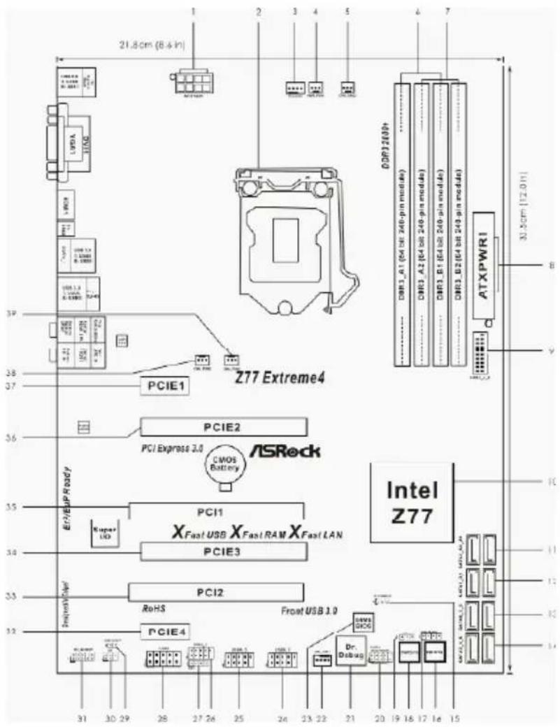
Motherboard Layout
text_image
21.8cm (6.4in) PCIE1 Z77 Extreme4 PCIE2 PCI Express 3.0 ASRock LMOS Battery Intel Z77 ReHS Frost USB 1.0 PCIE3 PCI1 X Fast USB X Fast RAM X Fast LAN PCIE4 Dr. Osteus ATXPWR1 ATXPWR1 DOR1 2600+ DOR1_A1 (64 bit 240-pin mod4s) DOR1_A2 (64 bit 240-pin mod4s) DOR1_B1 (64 bit 240-pin mod4s) DOR1_B2 (64 bit 240-pin mod4s) 33.5cm (12.01) B Y 39 38 37 36 35 34 33 32 31 30 29 28 27 26 25 24 23 22 21 20 19 18 17 16 15 31 30 29 28 27 26 25 24 23 22 21 20 19 18 17 16 151 ATX 12V Power Connector (ATX12V1)
2 1155-Pin CPU Socket
3 CPU Fan Connector (CPU_FAN1)
4 Power Fan Connector (PWR_FAN1)
5 CPU Fan Connector (CPU_FAN2)
6 2 x 240-pin DDR3 DIMM Slots (DDR3_A1, DDR3_B1, Black)
7 2 x 240-pin DDR3 DIMM Slots (DDR3_A2, DDR3_B2, Black)
8 ATX Power Connector (ATXPWR1)
9 USB 3.0 Header (USB3_4_5, Black)
10 Intel Z77 Chipset
11 SATA3 Connectors (SATA3_A0_A1, Gray)
12 SATA3 Connectors (SATA3_0_1, Gray)
13 SATA2 Connectors (SATA2_2_3, Black)
14 SATA2 Connectors (SATA2_4_5, Black)
15 Clear CMOS Jumper (CLRCMOS1)
16 Reset Switch (RSTBTN)
17 Chassis Speaker Header (SPEAKER1, Black)
18 Power Switch (PWRBTN)
19 Power LED Header (PLED1)
20 System Panel Header (PANEL1, Black)
21 Dr. Debug
22 Chassis Fan Connector (CHA_FAN1)
23 SPI Flash Memory (64Mb)
24 USB 2.0 Header (USB6_7, Black)
25 USB 2.0 Header (USB4_5, Black)
26 USB 2.0 Header (USB2_3, Black)
27 Consumer Infrared Module Header (CIR1, Gray)
28 COM Port Header (COM1)
29 HDMI_SPDIF Header (HDMI_SPDIF1, Black)
30 Infrared Module Header (IR1)
31 Front Panel Audio Header (HD_AUDIO1, Black)
32 PCI Express 2.0 x1 Slot (PCIE4, Black)
33 PCI Slot (PCI2, Black)
34 PCI Express 3.0 x16 Slot (PCIE3, Black)
35 PCI Slot (PCI1, Black)
36 PCI Express 3.0 x16 Slot (PCIE2, Black)
37 PCI Express 2.0 x1 Slot (PCIE1, Black)
38 Chassis Fan Connector (CHA_FAN2)
39 Chassis Fan Connector (CHA_FAN3)
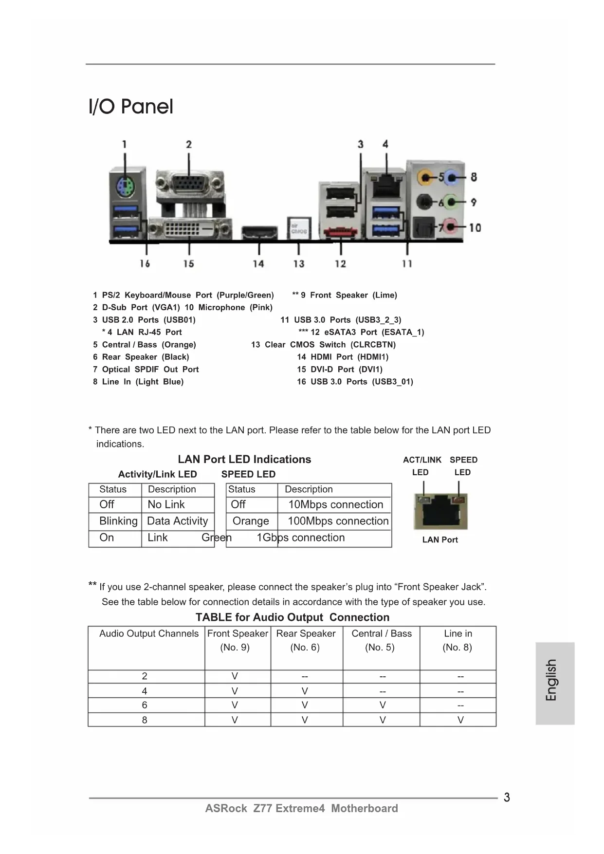
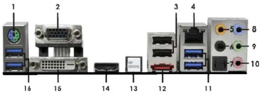
I/O Panel
text_image
1 2 3 4 5 8 6 9 7 10 11 12 13 14 15 16 17 18 19 20 21 22 23 24 25 26 27 28 29 30 31 32 33 34 35 36 37 38 39 40 41 42 43 44 45 46 47 48 49 501 PS/2 Keyboard/Mouse Port (Purple/Green) ** 9 Front Speaker (Lime)
2 D-Sub Port (VGA1) 10 Microphone (Pink)
3 USB 2.0 Ports (USB01)
11 USB 3.0 Ports (USB3_2_3)
* 4 LAN RJ-45 Port
*** 12 eSATA3 Port (ESATA_1)
5 Central / Bass (Orange)
13 Clear CMOS Switch (CLRCBTN)
6 Rear Speaker (Black)
14 HDMI Port (HDMI1)
7 Optical SPDIF Out Port
15 DVI-D Port (DVI1)
8 Line In (Light Blue)
16 USB 3.0 Ports (USB3_01)
* There are two LED next to the LAN port. Please refer to the table below for the LAN port LED indications.
LAN Port LED Indications
Activity/Link LED
| Status | Description |
| Off | No Link |
| Blinking | Data Activity |
| On | Link Gr |
SPEED LED
| Status | Description |
| Off | 10Mbps connection |
| Orange | 100Mbps connection |
| en 1Gbps connection | |
ACT/LINK SPEED

LAN Port
** If you use 2-channel speaker, please connect the speaker's plug into "Front Speaker Jack". See the table below for connection details in accordance with the type of speaker you use.
TABLE for Audio Output Connection
| Audio Output Channels | Front Speaker (No. 9) | Rear Speaker (No. 6) | Central / Bass (No. 5) | Line in (No. 8) |
| 2 | V | -- | -- | -- |
| 4 | V | V | -- | -- |
| 6 | V | V | V | -- |
| 8 | V | V | V | V |
To enable Multi-Streaming function, you need to connect a front panel audio cable to the front panel audio header. After restarting your computer, you will find "Mixer" tool on your system.
Please select "Mixer ToolBox"

, click "Enable playback multi-streaming", and click
"ok". Choose "2CH", "4CH", "6CH", or "8CH" and then you are allowed to select "Realtek HDA Primary output" to use Rear Speaker, Central/Bass, and Front Speaker, or select "Realtek HDA Audio 2nd output" to use front panel audio.
*** eSATA3 connector supports SATA Gen3 in cable 1M.
1. Introduction
Thank you for purchasing ASRock Z77 Extreme4 motherboard, a reliable motherboard produced under ASRock's consistently stringent quality control. It delivers excellent performance with robust design conforming to ASRock's commitment to quality and endurance.
This Quick Installation Guide contains introduction of the motherboard and step-by-step installation guide. More detailed information of the motherboard can be found in the user manual presented in the Support CD.

Because the motherboard specifications and the BIOS software might be updated, the content of this manual will be subject to change without notice. In case any modifications of this manual occur, the updated version will be available on ASRock website without further notice. You may find the latest VGA cards and CPU support lists on ASRock website as well. ASRock website http://www.asrock.com If you require technical support related to this motherboard, please visit our website for specific information about the model you are using. www.asrock.com/support/index.asp
1.1 Package Contents
ASRock Z77 Extreme4 Motherboard
(ATX Form Factor: 12.0-in x 8.6-in, 30.5 cm x 21.8 cm)
ASRock Z77 Extreme4 Quick Installation Guide
ASRock Z77 Extreme4 Support CD
2 x Serial ATA (SATA) Data Cables (Optional)
1 x I/O Panel Shield
1 x ASRock SLI_Bridge_2S Card

ASRock Reminds You...
To get better performance in Windows ^® 7/7 64-bit/Vista ^TM /Vista ^TM 64-bit, it is recommended to set the BIOS option in Storage Configuration to AHCI mode. For the BIOS setup, please refer to the "User Manual" in our support CD for details.
1.2 Specifications
* For detailed product information, please visit our website: http://www.asrock.com
| Platform - ATX Form Factor: 12.0-in x 8.6-in, 30.5 cm x 21.8 cm- Premium Gold Capacitor design (100% Japan-made high-quality Conductive Polymer Capacitors) | |
| CPU - Supports 3LGA1155 Package-Digi Power Design- 8 + 4 Power Phase Design-Supports Intel-Supports Intel-Supports Hyper-Threading Technology (seeCAUTION 1)-Supports IntelTechnology with Intel | ^rd and 2^nd Generation Intel ^ Core ^TM i7 / i5 / i3 in ^ Turbo Boost 2.0 Technology ^ K-Series unlocked CPU ^ Rapid Start Technology and Smart Connect ^ Ivy Bridge CPU |
| Chipset - Intel | ^ Z77 |
| Memory - Dual Channel DDR3 Memory Technology (seeCAUTION 2)- 4 x DDR3 DIMM slots-Supports DDR3 2800+(OC)/2400(OC)/2133(OC)/1866(OC)/1600/1333/1066 non-ECC, un-buffered memory-Max. capacity of system memory: 32GB (seeCAUTION 3)-Supports Intel | ^ Extreme Memory Profile (XMP)1.3/1.2 |
| Expansion Slot - 2 x PCI Express 3.0 x16 slots (PCIE2/PCIE3: single at x16 (PCIE2) / x8 (PCIE3) or dual at x8/x8 mode)(seeCAUTION 4)* PCIE 3.0 is only supported with Intel ^ Ivy Bridge CPU. With Intel ^ Sandy Bridge CPU, it only supports PCIE 2.0.- 2 x PCI Express 2.0 x 1 slots- 2 x PCI slots-Supports AMD Quad CrossFireXTMand CrossFireXTM-Supports NVIDIA ^ Quad SLITMand SLITM | |
| Graphics * Intelbe supported only integrated.-Supports IntelSync Video, IntelTechnology, IntelIntel-Pixel Shader 5.0,Pixel Shader 4.1,CPU.- Max. shared memory 1760MB (seeCAUTION 5) | ^ HD Graphics Built-in Visuals and the VGA outputs can with processors which are GPU ^ HD Graphics Built-in Visuals: Intel ^ Quick ^ InTru ^TM 3D, Intel ^ Clear Video HD ^ Insider ^TM , Intel ^ HD Graphics 2500/4000, ^ Advanced Vector Extensions (AVX) DirectX 11 with Intel ^ Ivy Bridge CPU.DirectX 10.1 with Intel ^ Sandy Bridge |
| - Three VGA Output options: D-Sub, DVI-D and HDMI(see CAUTION 6)- Supports HDMI 1.4a Technology with max. resolution up to 1920x1200 @ 60Hz- Supports DVI with max. resolution up to 1920x1200 @ 60Hz- Supports D-Sub with max. resolution up to 2048x1536 @ 75Hz- Supports Auto Lip Sync, Deep Color (12bpc), xvYCC and HBR (High Bit Rate Audio) with HDMI (Compliant HDMI monitor is required) (see CAUTION 7)- Supports HDCP function with DVI and HDMI ports- Supports Full HD 1080p Blu-ray (BD) / HD-DVD playback with DVI and HDMI ports | |
| Audio - 7.1 CH HD Audio with Content Protection(Realtek ALC898 Audio Codec)- Premium Blu-ray audio support | |
| LAN - PCIE x1 Gigabit LAN 10/100/1000 Mb/s- Broadcom BCM57781- Supports Wake-On-LAN- Supports Energy Efficient Ethernet 802.3az- Supports PXE | |
| Rear Panel I/O I/O Panel- 1 x PS/2 Keyboard/Mouse Port- 1 x D-Sub Port- 1 x DVI-D Port- 1 x HDMI Port- 1 x Optical SPDIF Out Port- 2 x Ready-to-Use USB 2.0 Ports- 1 x eSATA3 Connector- 4 x Ready-to-Use USB 3.0 Ports- 1 x RJ-45 LAN Port with LED (ACT/LINK LED and SPEED LED)- 1 x Clear CMOS Switch with LED- HD Audio Jack: Rear Speaker/Central/Bass/Line in/FrontSpeaker/Microphone (see CAUTION 8) | |
| SATA3 - 2 x SATA3 6.0 Gb/s connectors by Intel® Z77, support RAID(RAID 0, RAID 1, RAID 5, RAID 10, Intel Rapid Storage and Intel Smart Response Technology), NCQ, AHCI and Hot Plug functions | |
| - 2 x SATA3 6.0 Gb/s connectors by ASMedia ASM1061, support NCQ, AHCI and “Hot Plug” functions (SATA3_A1 connector is shared with eSATA3 port) | |
| USB3.0 - 2 x Rear up to 5Gb/s | USB 3.0 ports by Intel ® Z77, support USB 1.0/2.0/3.0 |
| - 2 x Rear USB 3.0 USB 1.0/2.0/3.0 up to 5Gb/s | ports by ASMedia ASM1042, support |
| - 1 x Front USB 3.0 ports), supports USB 1.0/2.0/3.0 up to 5Gb/s | header by Intel ® Z77 (supports 2 USB 3.0 |
| Connector - 4 x SATA2 3.0 Gb/s connectors, support RAID (RAID 0, RAID 1, RAID 5, RAID 10, Intel Rapid Storage and Intel Smart Response Technology), NCQ, AHCI and Hot Plug functions | - 4 x SATA3 6.0Gb/s connectors |
| - 1 x IR header | |
| - 1 x CIR header | |
| - 1 x COM port header | |
| - 1 x HDMI_SPDIF header | |
| - 1 x Power LED header | |
| - CPU/Chassis/Power FAN connector | |
| - 24 pin ATX power connector | |
| - 8 pin 12V power connector | |
| - Front panel audio connector | |
| - 3 x USB 2.0 headers (support 6 USB 2.0 ports) | |
| - 1 x USB 3.0 header (supports 2 USB 3.0 ports) | |
| - 1 x Dr. Debug with LED | |
| Smart Switch - 1 x | Clear CMOS Switch with LED |
| - 1 x Power Switch with LED | |
| - 1 x Reset Switch with LED | |
| BIOS Feature - 64Mb AMI UEFI Legal BIOS with GUI support | |
| - Supports “Plug and Play” | |
| - ACPI 1.1 Compliance Wake Up Events | |
| - Supports jumperfree | |
| - SMBIOS 2.3.1 Support | |
| - CPU Core, IGPU, DRAM, 1.8V PLL, VTT, VCCSA Voltage Multi-adjustment | |
| Support CD - Drivers, Utilities, AntiVirus Software (Trial Version), CyberLink MediaEspresso 6.5 Trial, ASRock MAGIX Multimedia Suite - OEM | |
| Unique Feature - ASRock Instant Boot | - ASRock Extreme Tuning Utility (AXTU) (see CAUTION 9) |
| - ASRock Instant Flash (see CAUTION 10)- ASRock APP Charger (see CAUTION 11)- ASRock SmartView (see CAUTION 12)- ASRock XFast USB (see CAUTION 13)- ASRock XFast LAN (see CAUTION 14)- ASRock XFast RAM (see CAUTION 15)- ASRock Crashless BIOS (see CAUTION 16)- Lucid Virtu Universal MVP (see CAUTION 17)* Lucid Virtu Universal MVP can be supported only with processors which are GPU integrated.- Hybrid Booster:- CPU Frequency Stepless Control (see CAUTION 18)- ASRock U-COP (see CAUTION 19)- Boot Failure Guard (B.F.G.)- Combo Cooler Option (C.C.O.) (see CAUTION 20)- Good Night LED | |
| Hardware - CPU Temperature SensingMonitor - Chassis Temperature Sensing- CPU/Chassis/Power Fan Tachometer- CPU/Chassis Quiet Fan (Allows Chassis Fan Speed Auto-Adjust by CPU Temperature)- CPU/Chassis Fan Multi-Speed Control- Voltage Monitoring: +12V, +5V, +3.3V, CPU Vcore | |
| OS - Microsoft XP / XP 64-bit compliant (see CAUTION 21) | ^® Windows ^® 7 / 7 64-bit / Vista ^TM / Vista ^TM 64-bit / |
| Certifications - FCC, CE, WHQL- ErP/EuP Ready (ErP/EuP ready power supply is required)(see CAUTION 22) | |
WARNING
Please realize that there is a certain risk involved with overclocking, including adjusting the setting in the BIOS, applying Untied Overclocking Technology, or using third-party overclocking tools. Overclocking may affect your system's stability, or even cause damage to the components and devices of your system. It should be done at your own risk and expense. We are not responsible for possible damage caused by overclocking.
CAUTION!
- About the settings of "Hyper Threading Technology", please check page 60 of the "User Manual" in the support CD.
- This motherboard supports Dual Channel Memory Technology. Before you implement Dual Channel Memory Technology, make sure to read the installation guide of memory modules on page 17 for proper installation.
- Due to the operating system limitation, the actual memory size may be less than 4GB for the reservation for system usage under Windows ^ 7 / Vista ^TM / XP. For Windows ^ OS with 64-bit CPU, there is no such limitation. You can use ASRock XFast RAM to utilize the memory that Windows ^ cannot use.
- Only PCIE2 and PCIE3 slots support Gen 3 speed. To run the PCI Express in Gen 3 speed, please install an Ivy Bridge CPU. If you install a Sandy Bridge CPU, the PCI Express will run only at PCI Express Gen 2 speed.
- The maximum shared memory size is defined by the chipset vendor and is subject to change. Please check Intel ^ website for the latest information.
- You can choose to use two of the three monitors only. D-Sub, DVI-D and HDMI monitors cannot be enabled at the same time. Besides, with the DVI-to-HDMI adapter, the DVI-D port can support the same features as HDMI port.
- xvYCC and Deep Color are only supported under Windows ^® 7 64-bit / 7. Deep Color mode will be enabled only if the display supports 12bpc in EDID. HBR is supported under Windows ^® 7 64-bit / 7 / Vista ^TM 64-bit / Vista ^TM .
- For microphone input, this motherboard supports both stereo and mono modes. For audio output, this motherboard supports 2-channel, 4-channel, 6-channel, and 8-channel modes. Please check the table on page 3 for proper connection.
- ASRock Extreme Tuning Utility (AXTU) is an all-in-one tool to ne-tune different system functions in a user-friendly interface, which includes Hardware Monitor, Fan Control, Overclocking, OC DNA and IES. In Hardware Monitor, it shows the major readings of your system. In Fan Control, it shows the fan speed and temperature for you to adjust. In Overclocking, you are allowed to overclock CPU frequency for optimal system performance. In OC DNA, you can save your OC settings as a profile and share it with your friends. Your friends then can load the OC profile to their own system to get the same OC settings. In IES (Intelligent Energy Saver), the voltage regulator can reduce the number of output phases to improve efficiency when the CPU cores are idle without sacrificing computing performance. Please visit our website for the operation procedures of ASRock Extreme Tuning Utility (AXTU).
ASRock website: http://www.asrock.com
-
ASRock Instant Flash is a BIOS flash utility embedded in Flash ROM. This convenient BIOS update tool allows you to update system BIOS without entering operating systems first like MS-DOS or Windows ^ . With this utility, you can press the
key during the POST or the key to enter into the BIOS setup menu to access ASRock Instant Flash. Just launch this tool and save the new BIOS file to your USB flash drive, floppy disk or hard drive, then you can update your BIOS only in a few clicks without preparing an additional floppy diskette or other complicated flash utility. Please be noted that the USB flash drive or hard drive must use FAT32/16/12 file system. -
If you desire a faster, less restricted way of charging your Apple devices, such as iPhone/iPad/iPod Touch, ASRock has prepared a wonderful solution for you - ASRock APP Charger. Simply install the APP Charger driver, it makes your iPhone charge much quickly from your computer and up to 40% faster than before. ASRock APP Charger allows you to quickly charge many Apple devices simultaneously and even supports continuous charging when your PC enters into Standby mode (S1), Suspend to RAM (S3), hibernation mode (S4) or power off (S5). With APP Charger driver installed, you can easily enjoy the marvelous charging experience.
ASRock website: http://www.asrock.com/Feature/AppCharger/index.asp
- ASRock SmartView, a new function for internet browsers, is the smart start page for IE that combines your most visited web sites, your history, your Facebook friends and your real-time newsfeed into an enhanced view for a more personal Internet experience. ASRock motherboards are exclusively equipped with the ASRock SmartView utility that helps you keep in touch with friends on-the-go. To use ASRock SmartView feature, please make sure your OS version is Windows® 7 / 7 64 bit / Vista™ / Vista™ 64 bit, and your browser version is IE8.
ASRock website: http://www.asrock.com/Feature/SmartView/index.asp
-
ASRock XFast USB can boost USB storage device performance. The performance may depend on the properties of the device.
-
ASRock XFast LAN provides a faster internet access, which includes the benefits listed below. LAN Application Prioritization: You can configure your application's priority ideally and/or add new programs. Lower Latency in Game: After setting online game's priority higher, it can lower the latency in games. Traffic Shaping: You can watch Youtube HD videos and download simultaneously. Real-Time Analysis of Your Data: With the status window, you can easily recognize which data streams you are transferring currently.
-
ASRock XFast RAM is a new function that is included into ASRock Extreme Tuning Utility (AXTU). It fully utilizes the memory space that cannot be used under Windows ^® OS 32-bit CPU. ASRock XFast RAM shortens the loading time of previously visited websites, making web surfing faster than ever. And it also boosts the speed of Adobe Photoshop 5 times faster. Another advantage of ASRock XFast RAM is that it reduces the frequency of accessing your SSDs or HDDs in order to extend their lifespan.
- ASRock Crashless BIOS allows users to update their BIOS without fear of failing. If power loss occurs during the BIOS update process, ASRock Crashless BIOS will automatically finish the BIOS update procedure after regaining power. Please note that BIOS files need to be placed in the root directory of your USB disk. Only USB2.0 ports support this feature.
- VIRTU Universal MVP includes the base features of Virtu Universal technology, which virtualizes integrated GPU and discrete GPU for best of breed functionality. It also features Virtual Vsync™ for no-compromise visual quality. With the added benefits of HyperFormance technology, VIRTU Universal MVP improves game performance by intelligently reducing redundant rendering tasks in the flow between the CPU, GPU and the display.
- Although this motherboard offers stepless control, it is not recommended to perform over-clocking. Frequencies other than the recommended CPU bus frequencies may cause instability of the system or damage the CPU.
- While CPU overheat is detected, the system will automatically shutdown. Before you resume the system, please check if the CPU fan on the motherboard functions properly and unplug the power cord, then plug it back again. To improve heat dissipation, remember to spray thermal grease between the CPU and the heatsink when you install the PC system.
- Combo Cooler Option (C.C.O.) provides the flexible option to adopt three different CPU cooler types, Socket LGA 775, LGA 1155 and LGA 1156. Please be noticed that not all the 775 and 1156 CPU Fan can be used.
- ASRock XFast RAM is not supported by Microsoft® Windows® XP / XP 64-bit. Intel® Smart Connect Technology and Intel® USB 3.0 ports are not supported by Microsoft® Windows® Vista™ / Vista™ 64-bit / XP / XP 64-bit.
- EuP stands for Energy Using Product, was a provision regulated by the European Union to define the power consumption for the completed system. According to EuP, the total AC power of the completed system should be under 1.00W in off mode condition. To meet EuP standards, an EuP ready motherboard and an EuP ready power supply are required. According to Intel's suggestion, the EuP ready power supply must meet the standard of 5v, and the standby power efficiency should be higher than 50% under 100 mA current consumption. For EuP ready power supply selection, we recommend you to check with the power supply manufacturer for more details.
2. Installation
This is an ATX form factor (12.0" x 8.6", 30.5 x 21.8 cm) motherboard. Before you install the motherboard, study the configuration of your chassis to ensure that the motherboard fits into it.

Make sure to unplug the power cord before installing or removing the motherboard. Failure to do so may cause physical injuries to you and damages to motherboard components.
2.1 Screw Holes
Place screws into the holes indicated by circles to secure the motherboard to the chassis.

Do not over-tighten the screws! Doing so may damage the motherboard.
2.2 Pre-installation Precautions
Take note of the following precautions before you install motherboard components or change any motherboard settings.
- Unplug the power cord from the wall socket before touching any components.
- To avoid damaging the motherboard's components due to static electricity, NEVER place your motherboard directly on the carpet or the like. Also remember to use a grounded wrist strap or touch a safety grounded object before you handle the components.
- Hold components by the edges and do not touch the ICs.
- Whenever you uninstall any component, place it on a grounded anti-static pad or in the bag that comes with the component.
- When placing screws into the screw holes to secure the motherboard to the chassis, please do not over-tighten the screws! Doing so may damage the motherboard.

Before you install or remove any component, ensure that the power is switched off or the power cord is detached from the power supply. Failure to do so may cause severe damage to the motherboard, peripherals, and/or components.
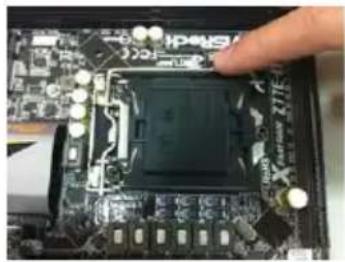
2.3 CPU Installation
In order to provide the LGA 1155 CPU sockets more protection and make the installation process easier, ASRock has added a new protection cover on top of the load plate to replace the former PnP caps that were under the load plate. For the installation of Intel ^® 1155-Pin CPUs with the new protection cover, please follow the steps below.

text_image
Load Plate Cover Load Lever Contact Array Socket Body1155-Pin Socket Overview

Before you insert the 1155-Pin CPU into the socket, please check if the CPU surface is unclean or if there are any bent pins in the socket. Do not force to insert the CPU into the socket if above situation is found. Otherwise, the CPU will be seriously damaged.
Step 1. Open the socket:
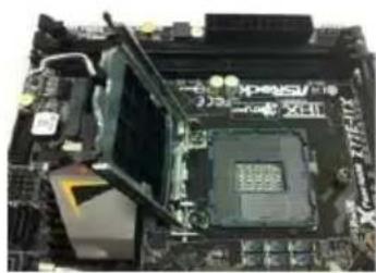
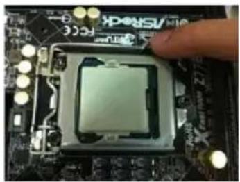
Step 1-1. Disengage the lever by pressing it down and sliding it out of the hook. You do not have to remove the protection cover.
natural_image
Close-up of a computer motherboard with a finger pointing to a central chip (no visible text or symbols)Step 1-2. Keep the lever positioned at about 135 degrees in order to flip up the load plate.
natural_image
Close-up of a computer motherboard with CPU socket and keyboard (no visible text or symbols)Step 2. Insert the 1155-Pin CPU:
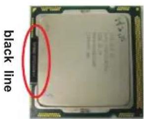
Step 2-1. Hold the CPU by the edge which is marked with a black line.
Step 2-2. Orient the CPU with the IHS (Integrated Heat Sink) up. Locate Pin1 and the two orientation key notches.
text_image
black line
text_image
orientation key notch Pin1 orientation key notch 1155-Pin CPU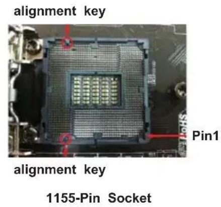
text_image
alignment key Pin1 alignment key 1155-Pin Socket
For proper installation, please ensure to match the two orientation key notches of the CPU with the two alignment keys of the socket.
Step 2-3. Carefully place the CPU into the socket.
Step 2-4. Verify that the CPU is within the socket and properly mated to the orient keys.
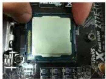
natural_image
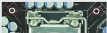
Close-up of a CPU socket being held, with no visible text or symbols on the socket itselfStep 3. Close the socket:
Step 3-1. Flip the load plate onto the IHS.
Step 3-2. Press down the load lever, and secure it with the load plate tab under the retention tab. The protection cover will automatically come off by itself.
natural_image
Close-up of a CPU socket on a motherboard with a finger pointing to it (no visible text or symbols)
Please save and replace the cover if the processor is removed. The cover must be placed if you wish to return the motherboard for after service.
2.4 Installation of CPU Fan and Heatsink
This motherboard is equipped with 1155-Pin socket that supports Intel 1155-Pin CPUs. Please adopt the type of heatsink and cooling fan compliant with Intel 1155-Pin CPU to dissipate heat. Before you install the heatsink, you need to spray thermal interface material between the CPU and the heatsink to improve heat dissipation. Ensure that the CPU and the heatsink are securely fastened and in good contact with each other. Then connect the CPU fan to the CPU_FAN connector (CPU_FAN1, see page 2, No. 3 or CPU_FAN2, see page 2, No.5).
For proper installation, please kindly refer to the instruction manuals of your CPU fan and heatsink.
Below is an example to illustrate the installation of the heatsink for 1155-Pin CPUs.
Step 1. Apply thermal interface material onto the center of the IHS on the socket's surface.

text_image
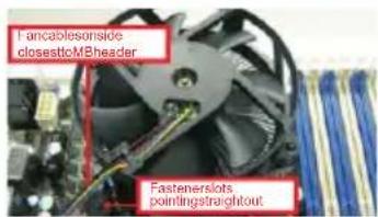
Apply Thermal InterfaceMaterialStep 2. Place the heatsink onto the socket. Ensure that the fan cables are oriented on side closest to the CPU fan connector on the motherboard (CPU_FAN1, see page 2, No. 3 or CPU_FAN2, see page 2. No.5).
text_image
F-ancablesnside closesto-MBheader Fastenerslots paintings straightoutStep 3. Align fasteners with the motherboard through-holes.
Step 4. Rotate the fastener clockwise, then press down on fastener caps with thumb to install and lock. Repeat with remaining fasteners.

text_image
PressDown (4Places)
If you press down the fasteners without rotating them clockwise, the heatsink cannot be secured on the motherboard.
Step 5. Connect fan header with the CPU fan connector on the motherboard.
Step 6. Secure redundant cable with tie-wrap to ensure the cable does not interfere with fan operation or contact other components.

Please be noticed that this motherboard supports Combo Cooler Option (C.C.O.), which provides flexible options to adopt three different CPU cooler types, Socket LGA 775, LGA 1155 and LGA 1156.
The white throughholes are for Socket LGA 1155/1156 CPU fan.
natural_image
Close-up of a circuit board with visible components and connectors (no text or symbols)2.5 Installation of Memory Modules (DIMM)
This motherboard provides four 240-pin DDR3 (Double Data Rate 3) DIMM slots, and supports Dual Channel Memory Technology. For dual channel configuration, you always need to install identical (the same brand, speed, size and chip-type) DDR3 DIMM pair in the slots: You have to install identical DDR3 DIMMs in Dual Channel A (DDR3_A1 and DDR3_B1; Black slots; see p.2 No. 6) or identical DDR3 DIMMs in Dual Channel B (DDR3_A2 and DDR3_B2; Black slots; see p.2 No. 7), so that Dual Channel Memory Technology can be activated. This motherboard also allows you to install four DDR3 DIMMs for dual channel configuration, please install identical DDR3 DIMMs in all four slots. You may refer to the Dual Channel Memory Configuration Table below.
Dual Channel Memory Configuration
| DDR3_A1 DDR3_A2 DDR3_B1(Black Slot) (Black Slot) (Black Slot) (Black Slot) | ||||
| (1) Populated | - Populated | - | ||
| (2) | - | Populated | - | Populated |
| (3)* | Populated Populated Populated Populated | |||
* For configuration (3), please install identical DDR3 DIMMs in all four slots.
- If you want to install two memory modules, for optimal compatibility and reliability, it is recommended to install them in the slots: DDR3_A1 and DDR3_B1, or DDR3_A2 and DDR3_B2.
- If only one memory module or three memory modules are installed in the DDR3 DIMM slots on this motherboard, it is unable to activate Dual Channel Memory Technology.
- If a pair of memory modules is NOT installed in the same Dual Channel, for example, installing a pair of memory modules in DDR3_A1 and DDR3_A2, it is unable to activate Dual Channel Memory Technology.
- It is not allowed to install a DDR or DDR2 memory module into DDR3 slot; otherwise, this motherboard and DIMM may be damaged.
- Some DDR3 1GB double-sided DIMMs with 16 chips may not work on this motherboard. It is not recommended to install them on this motherboard.
- For optimal compatibility and stability while overclocking memory frequency, it is recommended to install one memory module on DDR3_B2 slot or two memory modules on DDR3_A2 and DDR3_B2 slots.
Installing a DIMM
Please make sure to disconnect power supply before adding or removing DIMMs or the system components.
Step 1. Unlock a DIMM slot by pressing the retaining clips outward.
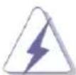
Step 2. Align a DIMM on the slot such that the notch on the DIMM matches the break on the slot.
text_image
O NOTCH break X NOTCH break XTUNE
The DIMM only fits in one correct orientation. It will cause permanent damage to the motherboard and the DIMM if you force the DIMM into the slot at incorrect orientation.
Step 3. Firmly insert the DIMM into the slot until the retaining clips at both ends fully snap back in place and the DIMM is properly seated.
2.6 Expansion Slots (PCI and PCI Express Slots)
There are 2 PCI slots and 4 PCI Express slots on this motherboard.
PCI slots: PCI slots are used to install expansion cards that have the 32-bit PCI interface.
PCIE slots: PCIE1 (PCIE 2.0 x1 slot) is used for a PCI Express x1 lane width card, such as a Gigabit LAN card, SATA2 card or ASRock Game Blaster, etc.
PCIE4 (PCIE 2.0 x1 slot) is used for a PCI Express x1 lane width card, such as a Gigabit LAN card, SATA2 card, etc.
PCIE2 (PCIE 3.0 x16 slot) is used for PCI Express x16 lane width graphics cards, or to install PCI Express graphics cards to support CrossFireX ^TM or SLI ^TM function.
PCIE3 (PCIE 3.0 x16 slot) is used for PCI Express x8 lane width graphics cards, or to install PCI Express graphics cards to support CrossFireX ^TM or SLI ^TM function.

- In single VGA card mode, it is recommended to install a PCI Express x16 graphics card on PCIE2 slot.
- In CrossFireX ^TM mode or SLI ^TM mode, please install the PCI Express x16 graphics cards on PCIE2 and PCIE3 slots. Therefore, both these two slots will work at x8 bandwidth.
- Please connect a chassis fan to the motherboard's chassis fan connector (CHA_FAN1, CHA_FAN2 or CHA_FAN3) when using multiple graphics cards for better thermal environment.
- Only PCIE2 and PCIE3 slots support Gen 3 speed. To run the PCI Express in Gen 3 speed, please install an Ivy Bridge CPU. If you install a Sandy Bridge CPU, the PCI Express will run only at PCI Express Gen 2 speed.
Installing an expansion card
Step 1. Before installing an expansion card, please make sure that the power supply is switched off or the power cord is unplugged. Please read the documentation of the expansion card and make necessary hardware settings for the card before you start the installation.
Step 2. Remove the system unit cover (if your motherboard is already installed in a chassis).
Step 3. Remove the bracket facing the slot that you intend to use. Keep the screws for later use.
Step 4. Align the card connector with the slot and press firmly until the card is completely seated on the slot.
Step 5. Fasten the card to the chassis with screws.
Step 6. Replace the system cover.
2.7 SLI ^TM and Quad SLI ^TM Operation Guide
This motherboard supports NVIDIA ^® SLI ^TM and Quad SLI ^TM (Scalable Link Interface) technology that allows you to install up to two identical PCI Express x16 graphics cards. Currently, NVIDIA ^® SLI ^TM technology supports Windows ^® XP / XP 64-bit / Vista ^TM / Vista ^TM 64-bit / 7 / 7 64-bit OS. NVIDIA ^® Quad SLI ^TM technology support Windows ^® Vista ^TM / Vista ^TM 64-bit / 7 / 7 64-bit OS only. Please follow the installation procedures in this section.

Requirements
-
For SLI ^TM technology, you should have two identical SLI ^TM -ready graphics cards that are NVIDIA ^ certified. For Quad SLI ^TM technology, you should have two identical Quad SLI ^TM -ready graphics cards (dual-GPU on each graphics card) that are NVIDIA ^ certified.
-
Make sure that your graphics card driver supports NVIDIA ^ SLI ^TM technology. Download the driver from NVIDIA ^ website (www.nvidia.com).
-
Make sure that your power supply unit (PSU) can provide at least the minimum power required by your system. It is recommended to use NVIDIA ^® certified PSU. Please refer to NVIDIA ^® website for details.
2.7.1 Graphics Card Setup
2.7.1.1 Installing Two SLI™-Ready Graphics Cards
Step 1. Install the identical SLI ^TM -ready graphics cards that are NVIDIA ^® certified because different types of graphics cards will not work together properly. (Even the GPU chips version shall be the same.) Insert one graphics card into PCIE2 slot and the other graphics card to PCIE3 slot. Make sure that the cards are properly seated on the slots.

natural_image
Electronic circuit board with multiple components and a large display screen (no visible text or symbols)Step2. If required, connect the auxiliary power source to the PCI Express graphics cards.
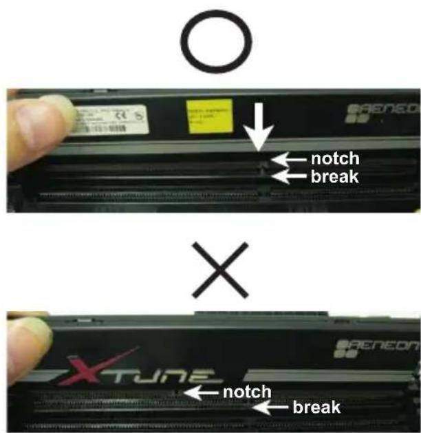
Step3. Align and insert the ASRock SLI_Bridge_2S Card to the goldfingers on each graphics card. Make sure the ASRock SLI_Bridge_2S Card is firmly in place.
text_image
SLLBridge.2S Card RoHS nsRockASRock SLI_Bridge_2S Card
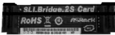
natural_image
Close-up of a black electronic component with a red oval highlighting a specific area, no visible text or symbols.Step4. Connect a VGA cable or a DVI cable to the monitor connector or the DVI connector of the graphics card that is inserted to PCIE2 slot.
2.7.2 Driver Installation and Setup
Install the graphics card drivers to your system. After that, you can enable the Multi- Graphics Processing Unit (GPU) feature in the NVIDIA ^® nView system tray utility.
Please follow the below procedures to enable the multi-GPU feature.
For Windows ^® XP / XP 64-bit OS:
(For SLI ^TM mode only)
A. Double-click NVIDIA Settings icon on your Windows ^® taskbar.

text_image
10:51 PMB. From the pop-up menu, select Set SLI and PhysX configuration. In Set PhysX GPU acceleration item, please select Enabled. In Select an SLI configuration item, please select Enable SLI. And click Apply.

text_image
Set SLI and PhysX configuration Select a Task... SLI: 100% image settings with previous SLI: 100% image settings with previous SLI: 100% image settings with previous SLI: 100% image settings with previous SLI: 100% image settings with previous SLI: 100% image settings with previous SLI: 100% image settings with previous SLI: 100% image settings with previous SLI: 100% Image Display SLI: 100% Image Display SLI: 100% Image Display SLI: 100% Image Display SLI: 100% Image Display SLI: 100% Image Display SLI: 100% Image Display SLI: 100% Image Display SLI: 100% Image Display SLI: 100% Image Display Select a Task... SLI: 100% image settings with previous SLI: 100% image settings with previous SLI: 100% image settings with previous SLI: 100% Image Display SLI: 100% Image Display SLI: 100% Image Display SLI: 100% Image Display SLI: 100% Image Display SLI: 150% SLI: 150% SLI: 150% SLI: 150% SLI: 150% SLI: 150% SLI: 150% SLI: 150% SLI: 150% SLI: 150% SLI: 150% SLI: 150% SLI: 150% SLI: Not selected SLI configurations SLI: Selected SLI SLI: Selected SLI SLI: Select the SLI from display SLI: Select the SLI from display SLI: Select the SLI from display SLI: Select the SLI from display SLI: Select the SLI from display SLI: Select the SLI from display SLI: Select the SLI from display SLI: Select the SLI from display SLI: Select the SLI from display SLI: Select the SLI from display SLI: Select the SLI from Display SLI: Select the SLI from Display SLI: Select the SLI from Display SLI: Select the SLI from Display SLI: Select the SLI from Display SLI: Select the SLI from Display SLI: Select the SLI from Display SLI: Select the SLI from Display SLI: Select the SLI from Display SLI: Select the SLI from Display SLI: Select the SLI from Displays SLI: Select the SLI from Displays SLI: Select the SLI from Displays SLI: Select the SLI from Displays SLI: Select the SLI from Displays SLI: Select the SLI from Displays SLI: Select the SLI from Displays SLI: Select the SLI from Displays SLI: Select the SLI from Displays SLI: Select the SLI from Displays SLI: Select the SLI from Display SLI: Select the SLI from Display SLI: Select the SLI from Display SLI: Select the SLI from Display SLI: Select the SLI from Display SLI: Select the SLI from Display SLI: Select the SLI from Display SLI: Select the SLI from Display SLI: Select the SLI from Display SLI: Select the SLI from displayC. Reboot your system.
D. You can freely enjoy the benefit of SLI ^TM feature.
For Windows ^® Vista ^TM / Vista ^TM 64-bit / 7 / 7 64-bit OS:
(For SLI ^TM and Quad SLI ^TM mode)
A. Click the Start icon on your Windows taskbar.
B. From the pop-up menu, select All Programs, and then click NVIDIA Corporation.
C. Select NVIDIA Control Panel tab.
D. Select Control Panel tab.

text_image
Default Programs Internet Explorer Windows Calendar Windows Contacts Windows Defender Windows DVD Maker Windows Fax and Scan Windows Live Messenger Download Windows Mail Windows Media Center Windows Media Player Windows Meeting Space Windows Movie Maker Windows Photo Gallery Windows Update Accessories Remove and Upgrades Games Maintenance NVIDIA Corporation NVIDIA Control Panel Control Panel e.g. Storage Startup Back Start Search Documents Pictures Music Games Search Recent Items Computer Network Connect 10 Control Panel Default Programs Help and SupportE. From the pop-up menu, select Set SLI and PhysX configuration. In Set PhysX GPU acceleration item, please select Enabled. In Select an SLI configuration item, please select Enable SLI. And click Apply.

text_image
NVIDIA Control Panel File Edit View 3D Settings Help Advanced Settings Select Tools • ID Settings • Adjust image settings with preview • Update video setup • Update video set-up • Update video set-up • Update video set-up • Update video set-up • Update video set-up • Update video set-up • Update video set-up • Update video set-up • Update video set-up • Update video set-up • Update video set-up • Update video set-up • Update video set-up • Update video set-up • Update video set-up • Update video set-up • Update video set-up • Update Video • Update Video • Update Video • Update Video • Update Video • Update Video • Update Video • Update Video • Update Video • Update Video • Update Video • Update Video • Update Video • Update Video • Update Video • Update Video • Update Video • Update Video • Update Video • Update Video • Update Video • Update Video • Update Video • Update Video • Update Video • Update Audio • Update Audio • Update Audio • Update Audio • Update Audio • Update Audio • Update Audio • Update Audio • Update Audio • Update Audio • Update Audio • Update Audio • Update Audio • Update Audio • Update Audio • Update Audio • Update Audio • Update Audio • Update Audio • Update Audio • Update Audio • Update Audio • Update Audio • Update Audio • Update Audio • Update Video • Update Video • Update Video • Update Video • Update Video • Update Video • Update Video • Update Video • Update Video • Update Video • Update Video • Update Video • Update Video • Update Video • Update Video • Update Video • Update Video • Update Video • Update Video • Update Video • Update Video • Update Video • Update Video • Update Video • UpdateVideo • UpdateVideo • UpdateVideo • UpdateVideo • UpdateVideo • UpdateVideo • UpdateVideo • UpdateVideo • UpdateVideo • UpdateVideo • UpdateVideo • UpdateVideo • UpdateVideo • UpdateVideo • UpdateVideo • UpdateVideo • UpdateVideo • UpdateVideo • UpdateVideo • UpdateVideo • UpdateVideo • UpdateVideo • UpdateVideo • UpdateVideo • UpdateVideo • UpdateAudio • UpdateAudio • UpdateAudio • UpdateAudio • UpdateAudio • UpdateAudio • UpdateAudio • UpdateAudio • UpdateAudio • UpdateAudio • UpdateAudio • UpdateAudio • UpdateAudio • UpdateAudio • UpdateAudio • UpdateAudio • UpdateAudio • UpdateAudio • UpdateAudio • UpdateAudio • UpdateAudio • UpdateAudioF. Reboot your system.
G. You can freely enjoy the benefit of SLI ^TM or Quad SLI ^TM feature.
* SLI™ appearing here is a registered trademark of NVIDIA® Technologies Inc., and is used only for identification or explanation and to the owners' benefit, without intent to infringe.
2.8 CrossFireX ^TM and Quad CrossFireX ^TM Operation Guide
This motherboard supports CrossFireX ^TM and Quad CrossFireX ^TM feature. CrossFireX ^TM technology offers the most advantageous means available of combining multiple high performance Graphics Processing Units (GPU) in a single PC. Combining a range of different operating modes with intelligent software design and an innovative interconnect mechanism, CrossFireX ^TM enables the highest possible level of performance and image quality in any 3D application. Currently CrossFireX ^TM feature is supported with Windows ^® XP with Service Pack 2 / Vista ^TM / 7 OS. Quad CrossFireX ^TM feature is supported with Windows ^® Vista ^TM / 7 OS only. Please check AMD website for ATI ^TM CrossFireX ^TM driver updates.
- If a customer incorrectly configures their system they will not see the performance benefits of CrossFireX ^TM . All three CrossFireX ^TM components, a CrossFireX ^TM Ready graphics card, a CrossFireX ^TM Ready motherboard and a CrossFireX ^TM Edition co-processor graphics card, must be installed correctly to benefit from the CrossFireX ^TM multi-GPU platform.
- If you pair a 12-pipe CrossFireX ^TM Edition card with a 16-pipe card, both cards will operate as 12-pipe cards while in CrossFireX ^TM mode.
2.8.1 Installing Two CrossFireX™-Ready Graphics Cards
Different CrossFireX ^TM cards may require different methods to enable CrossFireX ^TM feature. For other CrossFireX ^TM cards that AMD has released or will release in the future, please refer to AMD graphics card manuals for detailed installation guide.
Step 1. Insert one Radeon graphics card into PCIE2 slot and the other Radeon graphics card to PCIE3 slot. Make sure that the cards are properly seated on the slots.

natural_image
Close-up of a black and red Msi RS7TO CPU module with visible cooling fan and RAM slots (no text or symbols on main body)Step 2. Connect two Radeon graphics cards by installing CrossFire Bridge on CrossFire Bridge Interconnects on the top of Radeon graphics cards. (CrossFire Bridge is provided with the graphics card you purchase, not bundled with this motherboard. Please refer to your graphics card vendor for details.)
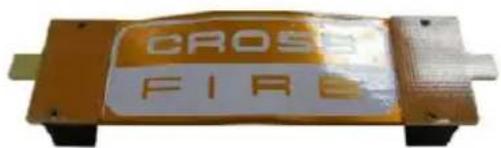
text_image
CROSS FIRECrossFire Bridge
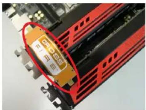
natural_image
Close-up of a red computer RAM module with a yellow component, no visible text or symbolsor
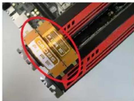
natural_image
Close-up of a computer RAM module with highlighted internal components (no visible text or symbols)Step 3. Connect the DVI monitor cable to the DVI connector on the Radeon graphics card on PCIE2 slot. (You may use the DVI to D-Sub adapter to convert the DVI connector to D-Sub interface, and then connect the D-Sub monitor cable to the DVI to D-Sub adapter.)
2.8.2 Driver Installation and Setup
Step 1. Power on your computer and boot into OS.
Step 2. Remove the ATI ^TM driver if you have any VGA driver installed in your system.
The Catalyst Uninstaller is an optional download. We recommend using this utility to uninstall any previously installed Catalyst drivers prior to installation. Please check AMD website for ATI ^TM driver updates.
Step 3. Install the required drivers to your system.
For Windows ^® XP OS:
A. ATI ^TM recommends Windows ^® XP Service Pack 2 or higher to be installed (If you have Windows ^® XP Service Pack 2 or higher installed in your system, there is no need to download it again):
http://www.microsoft.com/windowsxp/sp2/default.mspx
B. You must have Microsoft .NET Framework installed prior to downloading and installing the CATALYST Control Center. Please check Microsoft website for details.
For Windows ^® 7/Vista ^TM OS:
Install the CATALYST Control Center. Please check AMD website for details.
Step 4. Restart your computer.
Step 5. Install the VGA card drivers to your system, and restart your computer.
Then you will find "ATI Catalyst Control Center" on your Windows ^® taskbar.

text_image
10:54 AMATI Catalyst Control Center
Step 6. Double-click "ATI Catalyst Control Center". Click "View", select "CrossFireX™", and then check the item "Enable CrossFireX™". Select "2 GPUs" and click "Apply".

text_image
COSCOFIC Control Center Windows Windows Explorer Settings Software Settings Welcome Application Manager Application Manager Studio Editor Razor Properties 1 3D Color GraphPad Computer Logistics CrossFireX™ Graphics Adapter: T.A.T.H kitchen HD4800 Series | SyncEditor | GrossFireTM Advanced Environmental Systems only shall be controlling the processing power of this or more Graphics Processing Units (EPTA) Configure CrossFireTM ✓ Create CrossFire™ Choose from the following Perifier GPU combinations: [ ] CrossFire™ Modify CPU ATI FISOCN UNIFORMS "Real settings have not been applied, to ensure your other . CrossFireTM is a new user who needs the "Microsoft" or "Apply" Substrate wheel and solve your settings. Finish Apply Signat HelpAlthough you have selected the option "Enable CrossFire ^TM ", the CrossFireX ^TM function may not work actually. Your computer will automatically reboot. After restarting your computer, please confirm whether the option "Enable CrossFire ^TM in "ATI Catalyst Control Center" is selected or not; if not, please select it again, and then you are able to enjoy the benefits of CrossFireX ^TM .
Step 7. You can freely enjoy the benefits of CrossFireX ^TM or Quad CrossFireX ^TM .
* CrossFireX™ appearing here is a registered trademark of AMD Technologies Inc., and is used only for identification or explanation and to the owners' benefit, without intent to infringe.
* For further information of AMD CrossFireX™ technology, please check AMD's website for updates and details.
2.9 Dual Monitor and Surround Display Features
Dual Monitor Feature
This motherboard supports dual monitor feature. With the internal VGA output support (DVI-D, D-Sub and HDMI), you can easily enjoy the benefits of dual monitor feature without installing any add-on VGA cards to this motherboard. This motherboard also provides independent display controllers for DVI-D, D-Sub and HDMI to support dual VGA output so that DVI-D, D-sub and HDMI can drive same or different display contents.
To enable dual monitor feature, please follow the steps below:
- Connect a DVI-D monitor cable to the DVI-D port on the I/O panel, connect a D-Sub monitor cable to the D-Sub port on the I/O panel and connect a HDMI monitor cable to the HDMI port on the I/O panel.
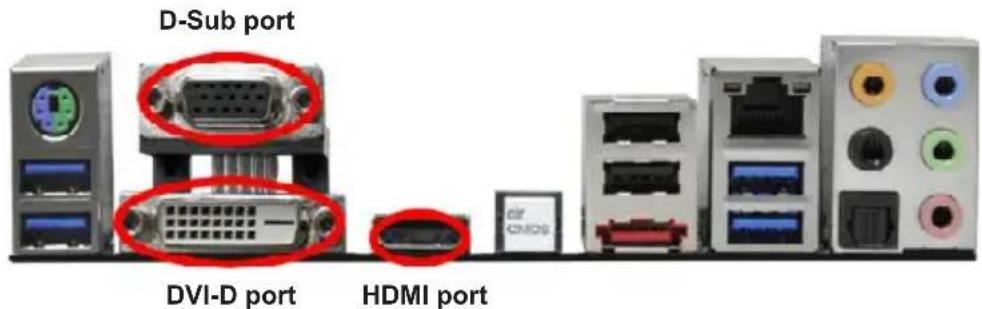
text_image
D-Sub port DVI-D port HDMI port- If you have already installed the onboard VGA driver from our support CD to your system, you can freely enjoy the benefits of dual monitor function after your system boots. If you haven't installed the onboard VGA driver yet, please install the onboard VGA driver from our support CD to your system and restart your computer.

D-Sub, DVI-D and HDMI monitors cannot be enabled at the same time. You can only choose the combination: DVI-D + HDMI, DVI-D + D-Sub, or HDMI + D-Sub.
Surround Display Feature
This motherboard supports surround display upgrade. With the internal VGA output support (DVI-D, D-Sub and HDMI) and external add-on PCI Express VGA cards, you can easily enjoy the benefits of surround display feature.
Please refer to the following steps to set up a surround display environment:
- Install the PCI Express VGA cards on PCIE2 and PCIE3 slots. Please refer to page 19 for proper expansion card installation procedures.
- Connect a DVI-D monitor cable to the DVI-D port on the I/O panel, connect a D-Sub monitor cable to the D-Sub port on the I/O panel and connect a HDMI monitor cable to the HDMI port on the I/O panel. Then connect other monitor cables to the corresponding connectors of the add-on PCI Express VGA cards on PCIE2 and PCIE3 slots.
- Boot your system. Press
or to enter UEFI setup. Enter "Share Memory" option to adjust the memory capability to [32MB], [64MB], [128MB], [256MB] or [512MB] to enable the function of D-sub. Please make sure that the value you select is less than the total capability of the system memory. If you do not adjust the UEFI setup, the default value of "Share Memory", [Auto], will disable D-Sub function when an add-on VGA card is inserted to this motherboard. - Install the onboard VGA driver and the add-on PCI Express VGA card driver to your system. If you have installed the drivers already, there is no need to install them again.
- Set up a multi-monitor display.
For Windows ^® XP / XP 64-bit OS:
Right click on desktop, choose "Properties", and select the "Settings" tab so that you can adjust the parameters of the multi-monitors according to the steps below.
A. Click the "Identify" button to display a large number on each monitor.
B. Right-click the display icon in the Display Properties dialog that you wish to be your primary monitor, and then select "Primary". When you use multiple monitors with your card, one monitor will always be Primary, and all additional monitors will be designated as Secondary.
C. Select the display icon identified by the number 2.
D. Click "Extend my Windows desktop onto this monitor".
E. Right-click the display icon and select "Attached", if necessary.
F. Set the appropriate "Screen Resolution" and "Color Quality" for the second monitor. Click "Apply" or "OK" to apply these new values.
G. Repeat steps C through E for the display icon identified by the numbers three to six.
For Windows ^® 7 / 7 64-bit / Vista ^TM / Vista ^TM 64-bit OS:
Right click the desktop, choose "Personalize", and select the "Display Settings" tab so that you can adjust the parameters of the multi-monitors according to the steps below.
A. Click the number "2" icon.
B. Click the items "This is my main monitor" and "Extend the desktop onto this monitor".
C. Click "OK" to save your change.
D. Repeat steps A through C for the display icons identified by the number three to six.
- Use Surround Display. Click and drag the display icons to positions representing the physical setup of your monitors that you would like to use. The placement of display icons determines how you move items from one monitor to another.
HDCP Function
HDCP function is supported on this motherboard. To use HDCP function with this motherboard, you need to adopt a monitor that supports HDCP function as well. Therefore, you can enjoy the superior display quality with high-definition HDCP encryption contents. Please refer to the instructions below for more details about HDCP function.
What is HDCP?
HDCP stands for High-Bandwidth Digital Content Protection, a specification developed by Intel ^® for protecting digital entertainment content that uses the DVI interface. HDCP is a copy protection scheme to eliminate the possibility of intercepting digital data midstream between the video source, or transmitter - such as a computer, DVD player or set-top box - and the digital display, or receiver - such as a monitor, television or projector. In other words, HDCP specification is designed to protect the integrity of content as it is being transmitted.
Products compatible with the HDCP scheme such as DVD players, satellite and cable HDTV set-top-boxes, as well as few entertainment PCs requires a secure connection to a compliant display. Due to the increase in manufacturers employing HDCP in their equipment, it is highly recommended that the HDTV or LCD monitor you purchase is compatible.
2.10 ASRock Smart Remote Installation Guide
ASRock Smart Remote is only used for ASRock motherboard with CIR header. Please refer to below procedures for the quick installation and usage of ASRock Smart Remote.
Step1. Find the CIR header located next to the USB 2.0 header on ASRock motherboard.
Step2. Connect the front USB cable to the USB 2.0 header (as below, pin 1-5) and the CIR header. Please make sure the wire assignments and the pin assignments are matched correctly.

text_image
USB6_7 USB 2.0 header (9-pin, black) CIR header (4-pin, gray)
text_image
USB_PWR P- P+ GND DUMMY USB6_7 1 2 3 4 5 CI R1 GND IRTX IRRX ATX+5VSB USB6_7 G71Step3. Install Multi-Angle CIR Receiver to the front USB port. If Multi-Angle CIR Receiver cannot successfully receive the infrared signals from MCE Remote Controller, please try to install it to the other front USB port.

natural_image
Illustration of various computer devices including desktop, tower, and remote control with a red signal wave (no text or symbols)3 CIR sensors in different angles

- Only one of the front USB port can support CIR function. When the CIR function is enabled, the other port will remain USB function.
- Multi-Angle CIR Receiver is used for front USB only. Please do not use the rear USB bracket to connect it on the rear panel. Multi-Angle CIR Receiver can receive the multi-direction infrared signals (top, down and front), which is compatible with most of the chassis on the market.
- The Multi-Angle CIR Receiver does not support Hot-Plug function. Please install it before you boot the system.
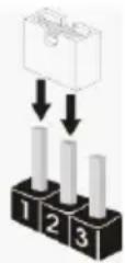
2.11 Jumpers Setup
The illustration shows how jumpers are setup. When the jumper cap is placed on pins, the jumper is "Short". If no jumper cap is placed on pins, the jumper is "Open". The illustration shows a 3-pin jumper whose pin1 and pin2 are "Short" when jumper cap is placed on these 2 pins.
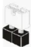
Short
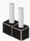
Open
Jumper Setting Description
Clear CMOS Jumper
(CLRCMOS1)
(see p.2, No. 15)
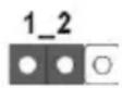

Clear CMOSDefault
Note: CLRCMOS1 allows you to clear the data in CMOS. To clear and reset the system parameters to default setup, please turn off the computer and unplug the power cord from the power supply. After waiting for 15 seconds, use a jumper cap to short pin2 and pin3 on CLRCMOS1 for 5 seconds. However, please do not clear the CMOS right after you update the BIOS. If you need to clear the CMOS when you just finish updating the BIOS, you must boot up the system first, and then shut it down before you do the clear-CMOS action. Please be noted that the password, date, time, user default profile, 1394 GUID and MAC address will be cleared only if the CMOS battery is removed.

The Clear CMOS Switch has the same function as the Clear CMOS jumper.
2.12 Onboard Headers and Connectors

Onboard headers and connectors are NOT jumpers. Do NOT place jumper caps over these headers and connectors. Placing jumper caps over the headers and connectors will cause permanent damage of the motherboard!
Serial ATA2 Connectors These four Serial ATA2 (SATA2)
(SATA2_2_3: see p.2, No. 13) connectors support SATA data (SATA2_4_5: see p.2, No. 14) cables for internal storage
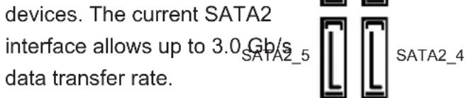
text_image
devices. The current SATA2 interface allows up to 3.0 Gb/s data transfer rate.Serial ATA3 Connectors These four Serial ATA3 (SATA3)
(SATA3_A0_A1: see p.2, No. 11) connectors support SATA data SATA3_A1 | SATA3_A0
(SATA3_0_1: see p.2, No. 12) cables for internal storage

text_image
devices. The current SATA3 interface allows up to 6.0 Gb/s SATA3_1 data transfer rate. If the eSATA3 SATA3_0port on the rear I/O has been connected, the internal SATA3_A1 will not function.
Serial ATA (SATA) Either end of the SATA data
Data Cable cable can be connected to the
(Optional) SATA / SATA2 / SATA3 hard disk or the SATA2 / SATA3 connector on this motherboard.
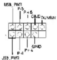
USB 2.0 Headers Besides two default USB 2.0
(9-pin USB2_3) ports on the I/O panel, there are
(see p.2, No. 26) three USB 2.0 headers on this
motherboard. Each USB 2.0 header can support two USB 2.0 P+2 GND
(9-pin USB4_5)
(see p.2, No. 25)
text_image
USB_PWR P-5 P+6 GND DUVMV JSB_PWR P-4 P+4 GNDports.
(9-pin USB6_7)
(see p.2, No. 24)

text_image
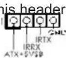
USB PWR P+7 P+7 GND DUMMY 1 GND P+6 U3B PWRUSB 3.0 Header Besides four default USB 3.0
(19-pin USB3_4_5) ports on the V/O panel, there is
(see p.2, No. 9) one USB 3.0 header on this
motherboard. This USB 3.0 GND - OIO IntA PS SETK header can support two USB 3.0
ports.
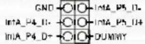
Infrared Module Header This header supports an
(5-pin IR1) optional wireless transmitting DUMMY
(see p.2, No. 30) and receiving infrared module.
Consumer Infrared Module Header This header can be used to
(4-pin CIR1) connect the remote
(see p.2 No. 27) controller receiver.
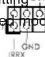
Front Panel Audio Header This is an interface for front
(9-pin HD_AUDIO1) panel audio cable that allows
(see p.2, No. 31) convenient connection and
control of audio devices.

text_image
PRESENCE# MIC_RET OUT_RET J_SENSE OUT2_R MIC2_R MIC2_L
-
High Definition Audio supports Jack Sensing, but the panel wire on the chassis must support HDA to function correctly. Please follow the instruction in our manual and chassis manual to install your system.
-
If you use AC'97 audio panel, please install it to the front panel audio header as below:
A. Connect Mic_IN (MIC) to MIC2_L.
B. Connect Audio_R (RIN) to OUT2_R and Audio_L (LIN) to OUT2_L.
C. Connect Ground (GND) to Ground (GND).
D. MIC_RET and OUT_RET are for HD audio panel only. You don't need to connect them for AC'97 audio panel.
E. To activate the front mic.
For Windows ^® XP / XP 64-bit OS:
Select "Mixer". Select "Recorder". Then click "FrontMic".
For Windows ^® 7 / 7 64-bit / Vista ^TM / Vista ^TM 64-bit OS:
Go to the "FrontMic" Tab in the Realtek Control panel. Adjust
"Recording Volume".
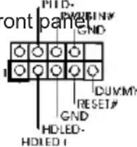
System Panel Header This header+accommodates
(9-pin PANEL1) several system front pa
(see p.2, No. 20) functions.
text_image
PTD- PWD GND Front panel 1 DUMMY RESET# GND HD-LED- HDLED 1
Connect the power switch, reset switch and system status indicator on the chassis to this header according to the pin assignments below. Note the positive and negative pins before connecting the cables.
PWRBTN (Power Switch):
Connect to the power switch on the chassis front panel. You may configure the way to turn off your system using the power switch.
RESET (Reset Switch):
Connect to the reset switch on the chassis front panel. Press the reset switch to restart the computer if the computer freezes and fails to perform a normal restart.
PLED (System Power LED):
Connect to the power status indicator on the chassis front panel. The LED is on when the system is operating. The LED keeps blinking when the system is in S1/S3 sleep state. The LED is off when the system is in S4 sleep state or powered off (S5).
HDLED (Hard Drive Activity LED):
Connect to the hard drive activity LED on the chassis front panel. The LED is on when the hard drive is reading or writing data.
The front panel design may differ by chassis. A front panel module mainly consists of power switch, reset switch, power LED, hard drive activity LED, speaker and etc. When connecting your chassis front panel module to this header, make sure the wire assignments and the pin assign-ments are matched correctly.
Chassis Speaker Header Please connect the chassis
(4-pin SPEAKER 1) speaker to this
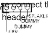
(see p.2, No. 17)
Power LED Header Please connect the chassis
(3-pin PLED1) power LED to this header to
(see p.2, No. 19) indicate system power status.
The LED is on when the system
is operating. The LED keeps
blinking in S1/S3 state. The
LED is off in S4 state or S5
state (power off).
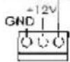
Chassis and Power Fan Connectors Please connect the fan cables
(4-pin CHA_FAN1) to the fan connectors and match
(see p.2, No. 22) the black wire to the ground pin.
CHA_FAN1, CHA_FAN2 and CJA_FAN_SPEED
(3-pin CHA_FAN2) CHA_FAN3 support Fan
(see p.2, No. 38) Control.
(3-pin CHA_FAN3)
(see p.2, No. 39)
(3-pin PWR_FAN1)
(see p.2, No. 4)
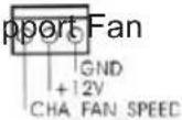
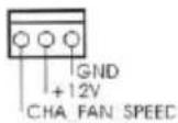
PWR_FAN_SPEED
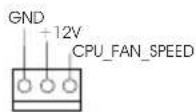
CPU Fan Connectors Please connect the CPU fan
(4-pin CPU_FAN1) cable to the connector and
(see p.2, No. 3) match the black wire to the
ground pin.


Though this motherboard provides 4-Pin CPU fan (Quiet Fan) support, the 3-Pin CPU fan still can work successfully even without the fan speed control function.
If you plan to connect the 3-Pin CPU fan to the CPU fan connector on this motherboard, please connect it to Pin 1-3.
Pin 1-3 Connected

3-Pin Fan Installation
(3-pin CPU_FAN2)
(see p.2, No. 5)
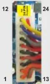
ATX Power Connector Please connect an ATX power
(24-pin ATXPWR1) supply to this connector.
(see p.2, No. 8)


Though this motherboard provides 24-pin ATX power connector, it can still work if you adopt a traditional 20-pin ATX power supply. To use the 20-pin ATX power supply, please plug your power supply along with Pin 1 and Pin 13.
20-Pin ATX Power Supply Installation
natural_image
Close-up of a multicolored electronic circuit board with labeled pins (1, 12, 13, 24), no readable text or symbols beyond labelsATX 12V Power Connector Please connect an ATX 12V
(8-pin ATX12V1) power supply to this connector.
(see p.2, No. 1)

Though this motherboard provides 8-pin ATX 12V power connector, it can still work if you adopt a traditional 4-pin ATX 12V power supply. To use the 4-pin ATX power supply, please plug your power supply along with Pin 1 and Pin 5.
4-Pin ATX 12V Power Supply Installation

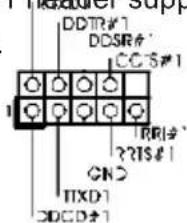
Serial port Header This COM1 header supports a
(9-pin COM1) serial port module.
(see p.2, No. 28)
(see p.2, No. 29) VGA card, allows the system to
connect HDMI Digital TV/
projector/LCD devices. Please
connect the HDMI_SPDIF
connector of HDMI VGA card to
this header.
2.13 Smart Switches
The motherboard has three smart switches: power switch, reset switch and clear CMOS switch, allowing users to quickly turn on/off or reset the sytem clear the CMOS values.
Power Switch Power Switch is a smart switch, (PWRBTN) allowing users to quickly turn (see p.2 No. 18) on/off the system

Reset Switch Reset Switch is a smart switch, (RSTBTN) allowing users to quickly reset (see p.2 No. 16) the system.

Clear CMOS Switch Clear CMOS Switch is a smart (CLRCBTN) switch, allowing users to quickly (see p.3 No. 13) clear the CMOS values.

2.14 Dr. Debug
Dr. Debug is used to provide code information, which makes troubleshooting even easier. Please see the diagrams below for reading the Dr. Debug codes.
| Status Code Description | |
| 0x00 Not used | |
| 0x01 Power on. | Reset type detection (soft/hard) |
| 0x02 AP initialization before microcode loading | |
| 0x03 North Bridge initialization before microcode loading | |
| 0x04 South Bridge initialization before microcode loading | |
| 0x05 OEM initialization before microcode loading | |
| 0x06 Microcode loading | |
| 0x07 AP initialization after microcode loading | |
| 0x08 North Bridge initialization after microcode loading | |
| 0x09 South Bridge initialization after microcode loading | |
| 0x0A OEM initialization after microcode loading | |
| 0x0B Cache initialization | |
| 0x0C - 0x0D Reserved for future AMI SEC error codes | |
| 0x0E Microcode not found | |
| 0x0F Microcode not loaded | |
| 0x10 PEI Core is started | |
| 0x11 Pre-memory CPU initialization is started | |
| 0x12 Pre-memory CPU initialization (CPU module specific) | |
| 0x13 Pre-memory CPU initialization (CPU module specific) | |
| 0x14 Pre-memory CPU initialization (CPU module specific) | |
| 0x15 Pre-memory North Bridge initialization is started | |
| 0x16 Pre-Memory North Bridge initialization (North Bridge module specific) | |
| 0x17 Pre-Memory North Bridge initialization (North Bridge module specific) | |
| 0x18 Pre-Memory North Bridge initialization (North Bridge module specific) | |
| 0x19 Pre-memory South Bridge initialization is started | |
| 0x1A Pre-memory South Bridge initialization (South Bridge module specific) | |
| 0x1B Pre-memory South Bridge initialization (South Bridge module specific) | |
| 0x1C Pre-memory South Bridge initialization (South Bridge module specific) | |
| 0x1D - 0x2A OEM pre-memory initialization codes | |
| 0x2B Memory initialization. Serial Presence Detect (SPD) data reading | |
| 0x2C Memory initialization. Memory presence detection | |
| 0x2D Memory initialization. Programming memory timing information | |
| 0x2E Memory initialization. Configuring memory | |
| 0x2F Memory initialization (other) | |
| 0x30 Reserved for ASL | |
| 0x31 Memory Installed | |
| 0x32 CPU post-memory initialization is started | |
| 0x33 CPU post-memory initialization. Cache initialization | |
| 0x34 CPU post-memory initialization. Application Processor(s) (AP) initialization | |
| 0x35 CPU post-memory initialization. Boot Strap Processor (BSP) selection | |
| 0x36 CPU post-memory initialization. System Management Mode (SMM) initialization | |
| 0x37 Post-Memory North Bridge initialization is started | |
| 0x38 Post-Memory North Bridge initialization (North Bridge module specific) | |
| 0x39 Post-Memory North Bridge initialization (North Bridge module specific) | |
| 0x3A Post-Memory North Bridge initialization (North Bridge module specific) | |
| 0x3B Post-Memory South Bridge initialization is started | |
| 0x3C Post-Memory South Bridge initialization (South Bridge module specific) | |
| 0x3D Post-Memory South Bridge initialization (South Bridge module specific) | |
| 0x3E Post-Memory South Bridge initialization (South Bridge module specific) | |
| 0x3F-0x4E OEM post memory initialization codes | |
| 0x4F DXE IPL is started | |
| 0x50 Memory initialization error. Invalid memory type or incompatible memory speed | |
| 0x51 Memory initialization error. SPD reading has failed | |
| 0x52 Memory initialization error. Invalid memory size or memory modules do not match | |
| 0x53 Memory initialization error. No usable memory detected | |
| 0x54 Unspecified memory initialization error | |
| 0x55 Memory not installed | |
| 0x56 Invalid CPU type or Speed | |
| 0x57 CPU mismatch | |
| 0x58 CPU self test failed or possible CPU cache error | |
| 0x59 CPU micro-code is not found or micro-code update is failed | |
| 0x5A Internal CPU error | |
| 0x5B reset PPI is not available | |
| 0x5C-0x5F Reserved for future AMI error codes | |
| 0xE0 S3 Resume is stared (S3 Resume PPI is called by the DXE IPL) | |
| 0xE1 S3 Boot Script execution | |
| 0xE2 Video repost | |
| 0xE3 OS S3 wake vector call | |
| 0xE4-0xE7 Reserved for future AMI progress codes | |
| 0xE8 S3 Resume Failed | |
| 0xE9 S3 Resume PPI not Found | |
| 0xEA S3 Resume Boot Script Error | |
| 0xEB S3 OS Wake Error | |
| 0xEC-0xEF Reserved for future AMI error codes | |
| 0xF0 Recovery condition triggered by firmware (Auto recovery) | |
| 0xF1 Recovery condition triggered by user (Forced recovery) | |
| 0xF2 Recovery process started | |
| 0xF3 Recovery firmware image is found | |
| 0xF4 Recovery firmware image is loaded | |
| 0xF5-0xF7 Reserved for future AMI progress codes | |
| 0xF8 Recovery PPI is not available | |
| 0xF9 Recovery capsule is not found | |
| 0xFA Invalid recovery capsule | |
| 0xFB - 0xFF Reserved for future AMI error codes | |
| 0x60 DXE Core is started | |
| 0x61 NVRAM initialization | |
| 0x62 | Installation of the South Bridge Runtime Services |
| 0x63 | CPU DXE initialization is started |
| 0x64 | CPU DXE initialization (CPU module specific) |
| 0x65 | CPU DXE initialization (CPU module specific) |
| 0x66 | CPU DXE initialization (CPU module specific) |
| 0x67 | CPU DXE initialization (CPU module specific) |
| 0x68 | PCI host bridge initialization |
| 0x69 | North Bridge DXE initialization is started |
| 0x6A | North Bridge DXE SMM initialization is started |
| 0x6B | North Bridge DXE initialization (North Bridge module specific) |
| 0x6C | North Bridge DXE initialization (North Bridge module specific) |
| 0x6D | North Bridge DXE initialization (North Bridge module specific) |
| 0x6E | North Bridge DXE initialization (North Bridge module specific) |
| 0x6F | North Bridge DXE initialization (North Bridge module specific) |
| 0x70 | South Bridge DXE initialization is started |
| 0x71 | South Bridge DXE SMM initialization is started |
| 0x72 | South Bridge devices initialization |
| 0x73 | South Bridge DXE Initialization (South Bridge module specific) |
| 0x74 | South Bridge DXE Initialization (South Bridge module specific) |
| 0x75 | South Bridge DXE Initialization (South Bridge module specific) |
| 0x76 | South Bridge DXE Initialization (South Bridge module specific) |
| 0x77 | South Bridge DXE Initialization (South Bridge module specific) |
| 0x78 | ACPI module initialization |
| 0x79 | CSM initialization |
| 0x7A - 0x7F | Reserved for future AMI DXE codes |
| 0x80 - 0x8F | OEM DXE initialization codes |
| 0x90 | Boot Device Selection (BDS) phase is started |
| 0x91 | Driver connecting is started |
| 0x92 | PCI Bus initialization is started |
| 0x93 | PCI Bus Hot Plug Controller Initialization |
| 0x94 | PCI Bus Enumeration |
| 0x95 | PCI Bus Request Resources |
| 0x96 | PCI Bus Assign Resources |
| 0x97 | Console Output devices connect |
| 0x98 | Console input devices connect |
| 0x99 | Super IO Initialization |
| 0x9A | USB initialization is started |
| 0x9B | USB Reset |
| 0x9C | USB Detect |
| 0x9D | USB Enable |
| 0x9E - 0x9F | Reserved for future AMI codes |
| 0xA0 | IDE initialization is started |
| 0xA1 | IDE Reset |
| 0xA2 | IDE Detect |
| 0xA3 | IDE Enable |
| 0xA4 | SCSI initialization is started |
| 0xA5 | SCSI Reset |
| 0xA6 | SCSI Detect |
| 0xA7 | SCSI Enable |
| 0xA8 | Setup Verifying Password |
| 0xA9 | Start of Setup |
| 0xAA | Reserved for ASL (see ASL Status Codes section below) |
| 0xAB | Setup Input Wait |
| 0xAC | Reserved for ASL (see ASL Status Codes section below) |
| 0xAD | Ready To Boot event |
| 0xAE | Legacy Boot event |
| 0xAF | Exit Boot Services event |
| 0xB0 | Runtime Set Virtual Address MAP Begin |
| 0xB1 | Runtime Set Virtual Address MAP End |
| 0xB2 | Legacy Option ROM Initialization |
| 0xB3 | System Reset |
| 0xB4 | USB hot plug |
| 0xB5 | PCI bus hot plug |
| 0xB6 | Clean-up of NVRAM |
| 0xB7 | Configuration Reset (reset of NVRAM settings) |
| 0xB8 - 0xBF Reserved for future AMI codes | |
| 0xC0 - 0xCF OEM BDS initialization codes | |
| 0xD0 | CPU initialization error |
| 0xD1 | North Bridge initialization error |
| 0xD2 | South Bridge initialization error |
| 0xD3 | Some of the Architectural Protocols are not available |
| 0xD4 | PCI resource allocation error. Out of Resources |
| 0xD5 | No Space for Legacy Option ROM |
| 0xD6 | No Console Output Devices are found |
| 0xD7 | No Console Input Devices are found |
| 0xD8 | Invalid password |
| 0xD9 | Error loading Boot Option (LoadImage returned error) |
| 0xDA | Boot Option is failed (StartImage returned error) |
| 0xDB | Flash update is failed |
| 0xDC | Reset protocol is not available |
2.15 Driver Installation Guide
To install the drivers to your system, please insert the support CD to your optical drive first. Then, the drivers compatible to your system can be auto-detected and listed on the support CD driver page. Please follow the order from up to bottom side to install those required drivers. Therefore, the drivers you install can work properly.
2.16 Installing Windows ^® 7 / 7 64-bit / Vista ^TM / Vista ^TM 64-bit With RAID Functions
If you want to install Windows ^ 7 / 7 64-bit / Vista ^TM / Vista ^TM 64-bit on your SATA / SATA2 / SATA3 HDDs with RAID functions, please refer to the document at the following path in the Support CD for detailed procedures:
..\ RAID Installation Guide
2.17 Installing Windows ^® 7 / 7 64-bit / Vista ^TM / Vista ^TM 64-bit / XP / XP 64-bit Without RAID Functions
If you want to install Windows ^ 7 / 7 64-bit / Vista ^TM / Vista ^TM 64-bit / XP / XP 64-bit OS on your SATA / SATA2 / SATA3 HDDs without RAID functions, please follow below procedures according to the OS you install.
2.17.1 Installing Windows ^® XP / XP 64-bit Without RAID Functions If you want to install Windows ^® XP / XP 64-bit OS on your SATA / SATA2 / SATA3 HDDs without RAID functions, please follow below steps.

AHCI mode is not supported under Windows ^® XP / XP 64-bit.
Using SATA / SATA2 / SATA3 HDDs without NCQ function
STEP 1: Set Up UEFI.
A. Enter UEFI SETUP UTILITY → Advanced screen → Storage Configuration.
B. Set the option "SATA Mode Selection" to [IDE] for SATA2_2 to SATA2_5 and SATA3_0 and SATA3_1 ports.
Set the option "ASMedia SATA3 Mode" to [IDE] for SATA3_A0 and SATA2_A1 ports.
STEP 2: Install Windows ^® XP / XP 64-bit OS on your system.
2.17.2 Installing Windows ^® 7 / 7 64-bit / Vista ^TM / Vista ^TM 64-bit Without RAID Functions
If you want to install Windows ^® 7 / 7 64-bit / Vista ^TM / Vista ^TM 64-bit OS on your SATA / SATA2 / SATA3 HDDs without RAID functions, please follow below steps.
Using SATA / SATA2 / SATA3 HDDs without NCQ function
STEP 1: Set Up UEFI.
A. Enter UEFI SETUP UTILITY → Advanced screen → Storage Configuration.
B. Set the option "SATA Mode Selection" to [IDE] for SATA2_2 to SATA2_5 and SATA3_0 and SATA3_1 ports.
Set the option "ASMedia SATA3 Mode" to [IDE] for SATA3_A0 and SATA2_A1 ports.
STEP 2: Install Windows ^® 7 / 7 64-bit / Vista ^TM / Vista ^TM 64-bit OS on your system.
Using SATA / SATA2 / SATA3 HDDs with NCQ function
STEP 1: Set Up UEFI.
A. Enter UEFI SETUP UTILITY → Advanced screen → Storage Configuration.
B. Set the option "SATA Mode Selection" to [AHCI] for SATA2_2 to SATA2_5 and SATA3_0 and SATA3_1 ports.
Set the option "ASMedia SATA3 Mode" to [AHCI] for SATA3_A0 and SATA2_A1 ports.
STEP 2: Install Windows ^® 7 / 7 64-bit / Vista ^TM / Vista ^TM 64-bit OS on your system.
3. BIOS Information
The Flash Memory on the motherboard stores BIOS Setup Utility. When you start up the computer, please press during the Power-On-Self-Test (POST) to enter BIOS Setup utility; otherwise, POST continues with its test routines. If you wish to enter BIOS Setup after POST, please restart the system by pressing
4. Software Support CD information
This motherboard supports various Microsoft® Windows® operating systems: 7 / 7 64-bit / Vista™ / Vista™ 64-bit / XP / XP 64-bit. The Support CD that came with the motherboard contains necessary drivers and useful utilities that will enhance motherboard features. To begin using the Support CD, insert the CD into your CD-ROM drive. It will display the Main Menu automatically if “AUTORUN” is enabled in your computer. If the Main Menu does not appear automatically, locate and double-click on the file “ASSETUP.EXE” from the BIN folder in the Support CD to display the menus.
1. Einführung
www.asrock.com/support/index.asp
1.1 Kartoninhalt
ASRock Z77 Extreme4 Motherboard
(ATX-Formfaktor: 30.5 cm x 21.8 cm; 12.0 Zoll x 8.6 Zoll)
ASRock Z77 Extreme4 Support-CD
Zwei Serial ATA (SATA) -Datenkabel (optional)
Ein I/O Shield
Ein ASRock SLI_Bridge_2S-Karte

ASRock erinnert...
ASRock-Website: http://www.asrock.com/Feature/SmartView/index.asp
(CLRCMOS1, 3-Pin jumper)
(siehe S.2, No. 15)
1 2

Default-
Einstellung
2_3

CMOS
löschen
Site web ASRock : http://www.asrock.com/Feature/AppCharger/index.asp
(USB4_5 br. 9) en charge 2 ports USB 2.0.
(voir p.2 No. 25)
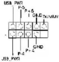
text_image
USB PWR P-5 P+6 I GND DUVMW JSB_PWR P-Δ P+2 GND(USB6_7 br. 9)
(voir p.2 No. 24)
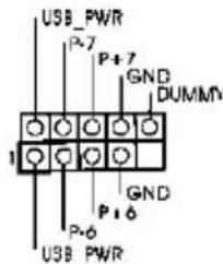
text_image
USB_PWR P-7 GND DUMMY 1 P-6 GND P-6 USB_PWRnatural_image
Close-up of a multicolored electronic circuit board with wires, labeled 1, 12, 24, and 13 (no readable text or symbols beyond labels)www.asrock.com/support/index.asp
(ATX Form Factor: 12.0-in x 8.6-in, 30.5 cm x 21.8 cm)
Sito ASRock: http://www.asrock.com/Feature/AppCharger/index.asp
text_image
Short Openwww.asrock.com/support/index.asp
text_image
Short OpenJumper Setting
Limpiar CMOS
(CLRCMOS1, jumper de 3 pins)
(ver p.2, N. 15)
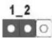
Valor predeterminado
(9-pin USB4_5) dos puertos USB 2.0
(vea p.2, N. 25)

text_image
USB_PWR P+6 GND_DLVMWY JSB_PWR P-4 GND P+4(9-pin USB6_7)
(vea p.2, N. 24)
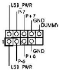
text_image
USB_PWR P-7 P+7 GND DUMMY 1 GND P-6 USB_PWRwww.asrock.com/support/index.asp
1.1 Комплектность
Материнская плата ASRock Z77 Extreme4
natural_image
Close-up of a multicolored electronic circuit board with visible traces and connectors (no text or symbols)text_image
CDTR#1 PODKI#S#R#MO#1 CC#1 TR#1# 2#TS#1 CNC TXD1 XDCD#1www.asrock.com/support/index.asp
ASRock internet sitesi: http://www.asrock.com/Feature/AppCharger/index.asp
(CLRCMOS1, 3-pinli jumper)
(bkz. s.2 No. 15)

Clear CMOSDefault
(SATA2_4_5: bkz. s.2, No. 14)
SATA2 arayüzü 3,0 Gb/sn veri
(SATA3_0_1: bkz. s.2, No. 12)
SATA3 arayüzü 6,0 Gb/sn veri SATA3_1
natural_image
Close-up of a colorful electronic component with numbered labels (1, 12, 24, 13) and no readable text or symbols beyond labels.natural_image
Close-up of a multicolored electronic circuit board with labeled pins (1, 12, 13, 24), no readable text or symbols beyond labelstext_image
Short Openジャンパ
設定 說明
CMOS の消去ジャンパ
(CLRCMOS1)
( ベージ 2 アイテム 15 参照)
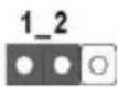
デフォルト設定
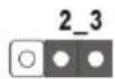
CMOS の消去
natural_image
Close-up of a multicolored electronic circuit board with numbered pins (1, 12, 24, 13) and no visible text or symbols on the board itself.ATX 12V コネクタ
(8 ピン ATX12V1)
ページ 2, アイテム 1 を参照

www.asrock.com/support/index.asp
1.1 包装盒内物品
华擎 Z77 Extreme4 主板
www.asrock.com/support/index.asp
1.1 白装盒队物品
華尊 Z77 Extreme4 主機板
text_image
Short Open接聊 設定
清咲 CMOS
(CLRCMOS1, 3 针型跳绳)
(见第2页第15项)
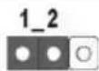
默認設置

清除 CMOS
Installing OS on a HDD Larger Than 2TB in AHCI Mode
This motherboard adopts UEFI BIOS that allows Windows ^® OS to be installed on a large size HDD (>2TB). Please follow the procedures below to install the operating system.
- Please make sure to use Windows ^® Vista ^™ 64-bit (with SP2 or above) or Windows ^® 7 64-bit (with SP1 or above).
- Press
or at system POST. Set AHCI Mode in UEFI Setup Utility > Advanced > Storage Configuration > SATA Mode. - Choose the item "UEFI:xxx" to boot in UEFI Setup Utility > Boot > Boot Option #1. ("xxx" is the device which contains your Windows® installation files. Normally it is an optical drive.) You can also press
to launch boot menu at system POST and choose the item "UEFI:xxx" to boot. - Start Windows ^® installation.
Installing OS on a HDD Larger Than 2TB in RAID Mode
This motherboard adopts UEFI BIOS that allows Windows ^® OS to be installed on a large size HDD (>2TB). Please follow the procedures below to install the operating system.
- Please make sure to use Windows ^® Vista ^™ 64-bit (with SP2 or above) or Windows ^® 7 64-bit (with SP1 or above).
- Copy Intel ^® RAID drivers into a USB flash disk. You can download the driver from ASRock's website and unzip the file into a USB flash disk OR copy the file from ASRock motherboard support CD. (please copy the files under following directory:
32 bit: ..\i386\Win7_Vista_Intel_v11.0.0.1032
64-bit: ..\AMD64\Win7-64_Vista64_Intel_v11.0.0.1032
- Create RAID array for you system. Please refer to "Intel RAID Installation Guide" file for details.
- Install Windows ^® Vista ^TM 64-bit / 7 64-bit:
A. Insert your Windows ^® Vista ^TM 64-bit / 7 64-bit installation disc to the optical drive.
B. Press
C. Start Windows ^® Installation. When you see “Where do you want to install Windows?” page, please click “Load Driver”.

text_image
Where do you want to install Windows? Name Total Size Free Space Disk 0 Unallocated Space 746.3 GB 746.3 GB Disk 1 Partition 1 100.0 MB 100.0 MB Disk 1 Partition 2 128.0 MB 120.0 MB Disk 1 Partition 3 5588.8 GB 5588.8 GB Drive option Load DiskD. Plug the USB flash disk into your USB port; select "Browse" to find the RAID driver. Then choose the directory (xx\AMD64) you have copied in the first step.

text_image
es ESP 1005-whql 1 EtronxHCI.Build.0.3.182.1 EtronxHCI.Build.0.5.368.3 firmware Floppy(v10.2.8.1002) AMD6.1 1386 OK Cancel RescanE. Please keep the USB flash disk installed until the system first reboot.
F. Continue to install OS by following the Windows® instructions.
- Follow Windows ^® Installation Guide to install OS.
If you install Windows ^® 7 64-bit / Vista ^TM 64-bit in a large hard disk (ex. Disk volume >2TB), it may take more time to boot into Windows ^® or install driver/utilities. If you encounter this problem, you will need to following instructions to fix this problem.
Windows® Vista™ 64-bit:
Microsoft ^® does not provide hotfix for this problem. The steps listed below are Microsoft ^® 's suggested solution:
A. Disable System Restore.
a. Type "systempropertiesprotection" in the Start Menu. Then press
"Enter".

text_image
Programs systempropertiesprotection QOS Documents Pictures Music Games Recent Items Computers Connect To Control Panel Default Programs Help and Support Search Everywhere Search the Internet systempropertiesprotectionb. De-select Local Disks for System Restore. Then Click "Turn System Restore Off" to confirm. Then Press "Ok".

text_image
System Properties Computer Name Hardware Advanced System Protection Before You can use restore points to undo unwanted system changes. How much do, some is returned? You can also use restore points to restore previous versions of files. called shadow copies. How on / Use previous versions? System Restore helps you restore your computer's system that is an earlier point in time. System Restore... & monitor restore points Create restore points automatically on the selected disk: Portable Disk Local Disk (C:) (System) Local Disk (D:) Most recent restore point 2/14/2011 5:09:30 AM None System Protection Are you sure you want to turn System Restore off? All existing restore points on the disk will be deleted, and no new ones will be created. 2. Turn System Restore Off CancelB. Disable "Volume Shadow Copy" service.
a. Type "computer management" in the Start Menu, then press "Enter".
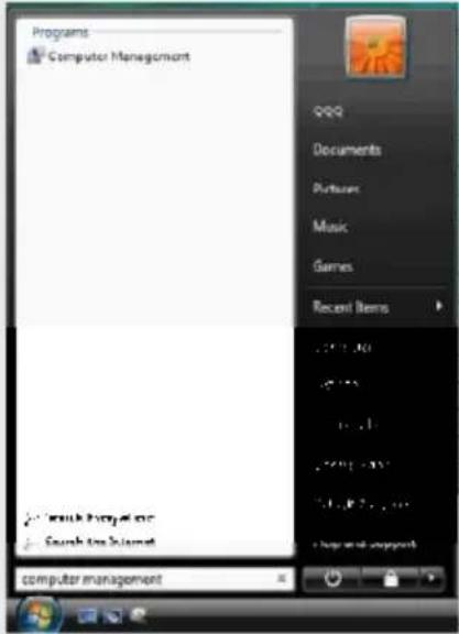
text_image
Programs Computer Management QQQ Documents Portions Music Games Recent Items • Watch Webpage one • Search Web Internet computer managementb. Go to "Services and Applications>Services"; Then double click "Volume
Shadow Copy".
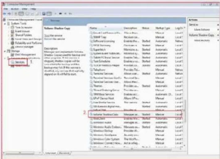
text_image
Computer Management System Tools Time Subenarios Start Values Share Providers Final Time and Settings Reliability and Performance Service Manager Storage End Management Automotive Systems Services 1 Software Controls Description Shading and Implementation Volume, Shading Coped and/or Distribution and other programs. If this service is shaped, Shadow copies will be on which the following functions: Backup may not. If this service is default, any services that significantly dipend on it will fail to start. Name Description Status Market Type Log To Services Sales Actions Volume Shadow Copy Import Features Volume Shadow Copy Services 1 Name Description Status Market Type Log To Services 1 Shading Coped and/or Distribution and other programs. If this service is shaped, Shadow copies will be on which the following functions: Backup may not. If this service is default, any services that significantly dipend on it will fail to start. Name Description Status Market Type Log To Services 1 Shading Coped and/or Distribution and other programs. If this service is shaped, Shadow copies will be on which the following functions: Backup may not. If this service is default, any services that significantly dipend on it will fail to start. Name Description Status Market Type Log To Services 1 Shading Coped and/or Distribution and other program. If this service is shaped, Shadow copies will be on which the following functions: Backup may not. If this service is default, any services that significantly dipend on it will fail to start.c. Set "Startup type" to "Disable" then Click "OK".
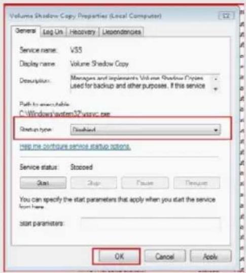
text_image
Volume Shadow Copy Properties (Local Computer) Servers Log On Recovery Dependencies Service name: VSS Display name: Volume Shadow Copy Description: Managers and implements Volume Shadow Copies Used for backup and other purposes. If this service Path to anchor tables C:\Windows\system32\msvc.exe Startup type: Disabled Help me configure service startup options. Service status: Stocoid Start Stop Finish Resume You can specify the start parameters that apply when you start the service from here: start parameters: OK Cancel ApplyC. Reboot your system.
D. After reboot, please start to install motherboard drivers and utilities.
Windows® 7 64-bit:
A. Please request the hotfix KB2505454 through this link: http://support.microsoft.com/kb/2505454/
B. After installing Windows ^® 7 64-bit, install the hotfix kb2505454. (This may take a long time; >30 mins.)
C. Reboot your system. (It may take about 5 minutes to reboot.)
D. Windows ^® will install this hotfix then reboot by itself.
E. Please start to install motherboard drivers and utilities.
- Finish.