
X570 Extreme4 - Motherboard ASROCK - Free user manual and instructions
Find the device manual for free X570 Extreme4 ASROCK in PDF.

| Product Type | Motherboard |
| Brand | ASRock |
| Model | X570 Extreme4 |
| Form Factor | ATX (305 x 244 mm) |
| Processor Socket | AM4 |
| Chipset | AMD X570 |
| Memory | 4 x DDR4 DIMM, max 128 GB, dual channel, supports ECC and non-ECC, frequencies up to 4666+ MHz (OC) |
| Expansion Slots | 2 x PCIe 4.0 x16, 3 x PCIe 4.0 x1, 1 x M.2 Key E (WiFi/BT) |
| Storage | 8 x SATA3 6 Gb/s (RAID 0/1/10), 1 x Hyper M.2 (PCIe Gen4 x4), 1 x Hyper M.2 (SATA3/PCIe Gen4 x4) |
| Audio | Realtek ALC1220, 7.1 HD channels, Purity Sound 4, 600 ohm headphone amplifier |
| Network | Gigabit LAN Intel I211AT |
| USB (rear panel) | 1 x USB 3.2 Gen2 Type-A, 1 x USB 3.2 Gen2 Type-C, 6 x USB 3.2 Gen1 |
| USB (internal headers) | 2 x USB 2.0, 2 x USB 3.2 Gen1, 1 x USB 3.2 Gen1 Type-C |
| Video Outputs | 1 x HDMI 2.0 (4K@60Hz, HDR, HDCP 2.2) |
| Power Connectors | 1 x 24-pin ATX, 1 x 8-pin + 1 x 4-pin CPU |
| Fan Connectors | 1 x CPU, 1 x CPU/water pump, 4 x chassis/water pump |
| RGB Lighting | 1 x AMD fan LED header, 1 x RGB LED header, 1 x addressable LED header |
| BIOS | UEFI AMI with graphical interface, ACPI 5.1 compliant, SMBIOS 2.3 |
| Operating System | Microsoft Windows 10 64-bit |
| Certifications | FCC, CE, ErP/EuP |
| Care and Cleaning | Clean with a dry, lint-free cloth. Avoid any liquids. Disconnect before cleaning. |
| Safety | Use a certified power supply. Do not expose to moisture. Handle carefully to avoid electrostatic discharge. |
| Estimated Weight | Approximately 1.5 kg (board only) |
Frequently Asked Questions - X570 Extreme4 ASROCK
User questions about X570 Extreme4 ASROCK
0 question about this device. Answer the ones you know or ask your own.
Ask a new question about this device
Download the instructions for your Motherboard in PDF format for free! Find your manual X570 Extreme4 - ASROCK and take your electronic device back in hand. On this page are published all the documents necessary for the use of your device. X570 Extreme4 by ASROCK.
USER MANUAL X570 Extreme4 ASROCK
Copyright©2019 ASRock INC. All rights reserved.
Copyright Notice:
No part of this documentation may be reproduced, transcribed, transmitted, or translated in any language, in any form or by any means, except duplication of documentation by the purchaser for backup purpose, without written consent of ASRock Inc.
Products and corporate names appearing in this documentation may or may not be registered trademarks or copyrights of their respective companies, and are used only for identification or explanation and to the owners' benefit, without intent to infringe.
Disclaimer:
Specifications and information contained in this documentation are furnished for informational use only and subject to change without notice, and should not be constructed as a commitment by ASRock. ASRock assumes no responsibility for any errors or omissions that may appear in this documentation.
With respect to the contents of this documentation, ASRock does not provide warranty of any kind, either expressed or implied, including but not limited to the implied warranties or conditions of merchantability or fitness for a particular purpose.
In no event shall ASRock, its directors, officers, employees, or agents be liable for any indirect, special, incidental, or consequential damages (including damages for loss of profits, loss of business, loss of data, interruption of business and the like), even if ASRock has been advised of the possibility of such damages arising from any defect or error in the documentation or product.

This device complies with Part 15 of the FCC Rules. Operation is subject to the following two conditions:
(1) this device may not cause harmful interference, and
(2) this device must accept any interference received, including interference that may cause undesired operation.
CALIFORNIA, USA ONLY
The Lithium battery adopted on this motherboard contains Perchlorate, a toxic substance controlled in Perchlorate Best Management Practices (BMP) regulations passed by the California Legislature. When you discard the Lithium battery in California, USA, please follow the related regulations in advance.
"Perchlorate Material-special handling may apply, see www.dtsc.ca.gov/hazardouswaste/perchlorate"
ASRock Website: http://www.asrock.com

AUSTRALIA ONLY
Our goods come with guarantees that cannot be excluded under the Australian Consumer Law. You are entitled to a replacement or refund for a major failure and compensation for any other reasonably foreseeable loss or damage caused by our goods. You are also entitled to have the goods repaired or replaced if the goods fail to be of acceptable quality and the failure does not amount to a major failure. If you require assistance please call ASRock Tel: +886-2-28965588 ext.123 (Standard International call charges apply)
The terms HDMI ^® and HDMI High-Definition Multimedia Interface, and the HDMI logo are trademarks or registered trademarks of HDMI Licensing LLC in the United States and other countries.

HIGH-DEFINITION MULTIMEDIA INTERFACE
Manufactured under license under U.S. Patent Nos: 5,956,674; 5,974,380; 6,487,535; 7,003,467 & other U.S. and worldwide patents issued & pending. DTS, the Symbol, & DTS and the Symbol together is a registered trademark & DTS Connect, DTS Interactive, DTS Neo:PC are trademarks of DTS, Inc. Product includes software.
© DTS, Inc., All Rights Reserved.

Connect

Interactive

Neo:PC
Motherboard Layout
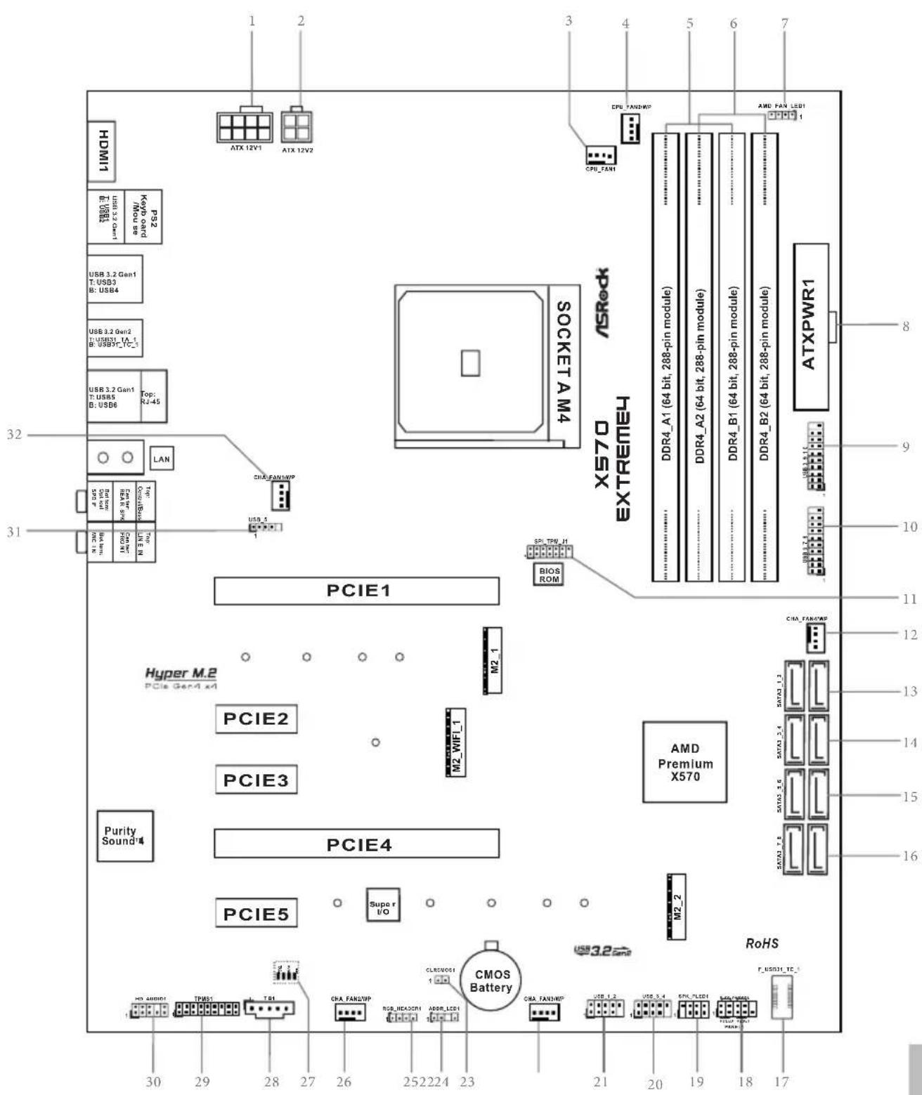
No. Description
18 pin 12V Power Connector (ATX12V1)
2 4 pin 12V Power Connector (ATX12V2)
3 CPU Fan Connector (CPU_FAN1)
4 CPU / Waterpump Fan Connector (CPU_FAN2/WP)
5 2 x 288-pin DDR4 DIMM Slots (DDR4_A1, DDR4_B1)
6 2 x 288-pin DDR4 DIMM Slots (DDR4_A2, DDR4_B2)
7 AMD FAN LED Header (AMD_FAN_LED1)
8 ATX Power Connector (ATXPWR1)
9 USB 3.2 Gen1 Header (USB3_9_10)
10 USB 3.2 Gen1 Header (USB3_7_8)
11 SPI TPM Header (SPI_TPM_J1)
12 Chassis / Waterpump Fan Connector (CHA_FAN4/WP)
13 SATA3 Connectors (SATA3_1_2)
14 SATA3 Connectors (SATA3_3_4)
15 SATA3 Connectors (SATA3_5_6)
16 SATA3 Connectors (SATA3_7_8)
17 Front Panel Type C USB 3.2 Gen1 Header (F_USB31_TC_1)
18 System Panel Header (PANEL1)
19 Power LED and Speaker Header (SPK_PLED1)
20 USB 2.0 Header (USB_3_4)
21 USB 2.0 Header (USB_1_2)
22 Chassis/Water Pump Fan Connector (CHA_FAN3/WP)
23 Clear CMOS Jumper (CLRCMOS1)
24 Addressable LED Header (ADDR_LED1)
25 RGB LED Header (RGB_HEADER1)
26 Chassis / Waterpump Fan Connector (CHA_FAN2/WP)
27 Post Status Checker (PSC)
28 Thunderbolt AIC Header (TB1)
29 TPM Header (TPMS1)
30 Front Panel Audio Header (HD_AUDIO1)
31 AMD LED Fan USB Header (USB_5)
32 CPU / Waterpump Fan Connector (CHA_FAN1/WP)
I/O Panel
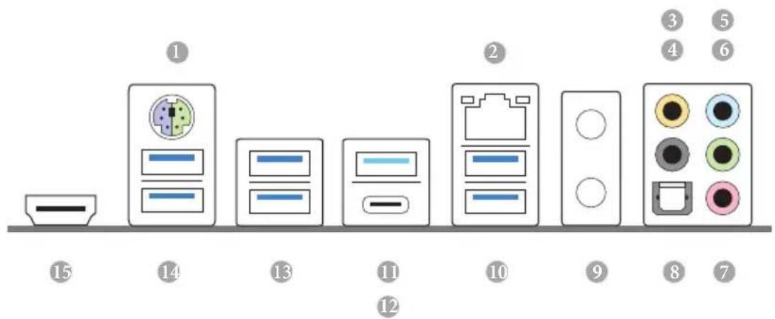
No. Description No. Description
1 PS/2 Mouse/Keyboard Port 9 Antenna Bracket (on I/O Panel Shield)
2 LAN RJ-45 Port* 10 USB 3.2 Gen1 Ports (USB3_56)***
3 Central / Bass (Orange) 11 USB 3.2 Gen2 Type-A Port (USB31_TA_1)
4 Rear Speaker (Black) 12 USB 3.2 Gen2 Type-C Port (USB31_TC_1)
5 Line In (Light Blue) 13 USB 3.2 Gen1 Ports (USB3_34)
6 Front Speaker (Lime) ^** 14 USB 3.2 Gen1 Ports (USB3_12)
7 Microphone (Pink) 15 HDMI Port
8 Optical SPDIF Out Port
* There are two LEDs on each LAN port. Please refer to the table below for the LAN port LED indications.
ACT/LINK LED
| Activity / Link LED Speed LED | |||
| Status Description Status Description | |||
| Off No Link Off | 10Mbps connection | ||
| Blinking | Data Activity | Orange | 100Mbps connection |
| On Link Green | 1Gbps connection | ||
** If you use a 2-channel speaker, please connect the speaker's plug into "Front Speaker Jack". See the table below for connection details in accordance with the type of speaker you use.
| Audio Output Channels | Front Speaker (No. 6) | Rear Speaker (No. 4) | Central / Bass (No. 3) | Line In (No.5) |
| 2 V -- -- -- | ||||
| 4 V V -- -- | ||||
| 6 V V V -- | ||||
| 8 V V V V |
*** ACPI wake-up function is not supported on USB3_56 ports.
Chapter 1 Introduction
Thank you for purchasing ASRock X570 Extreme4 motherboard, a reliable motherboard produced under ASRock's consistently stringent quality control. It delivers excellent performance with robust design conforming to ASRock's commitment to quality and endurance.

Because the motherboard specifications and the BIOS software might be updated, the content of this documentation will be subject to change without notice. In case any modifications of this documentation occur, the updated version will be available on ASRock's website without further notice. If you require technical support related to this motherboard, please visit our website for specific information about the model you are using. You may find the latest VGA cards and CPU support list on ASRock's website as well. ASRock website http://www.asrock.com.
1.1 Package Contents
• ASRock X570 Extreme4 Motherboard (ATX Form Factor)
• ASRock X570 Extreme4 Quick Installation Guide
• ASRock X570 Extreme4 Support CD
• 4 x Serial ATA (SATA) Data Cables (Optional)
• 3 x Screws for M.2 Socket (Optional)
• 2 x Standoffs for M.2 Sockets (Optional)
1.2 Specifications
Platform
- ATX Form Factor
- 2oz Copper PCB
CPU
- Supports AMD AM4 socket Ryzen™ 2000 and 3000 series processors
- Intersil Digital PWM
• 10 Power Phase design
Chipset
- AMD X570
Memory
• Dual Channel DDR4 Memory Technology
• 4 x DDR4 DIMM Slots
- AMD Ryzen series CPUs (Matisse) support DDR4 4666+ (OC)/4400(OC)/4300(OC)/4266(OC)/4200(OC)/4133(OC)/3466(OC)/3200/2933/2667/2400/2133 ECC & non-ECC, unbuffered memory*
- AMD Ryzen series CPUs (Pinnacle Ridge) support DDR4 3600+(OC)/3466(OC)/3200(OC)/2933/2667/2400/2133 ECC & non-ECC, un-buffered memory*
- AMD Ryzen series CPUs (Picasso) support DDR4 3466+ | (OC)/3200(OC)/2933/2667/2400/2133 non-ECC, un-buffered memory*
* For Ryzen Series CPUs (Picasso), ECC is only supported with PRO CPUs.
* Please refer to Memory Support List on ASRock's website for more information. (http://www.asrock.com/)
* Please refer to page 25 for DDR4 UDIMM maximum frequency support.
• Max. capacity of system memory: 128GB
• 15μ Gold Contact in DIMM Slots
Expansion
AMD Ryzen series CPUs (Matisse)
Slot
- 2 x PCI Express 4.0 x16 Slots (single at x16 (PCIE1); dual at x16 (PCIE1) / x4 (PCIE4))*
AMD Ryzen series CPUs (Pinnacle Ridge)
- 2 x PCI Express 3.0 x16 Slots (single at x16 (PCIE1); dual at x16 (PCIE1) / x4 (PCIE4))*
- 2 x PCI Express 3.0 x16 Slots (single at x8 (PCIE1); dual at x8 (PCIE1) / x4 (PCIE4))*
* Supports NVMe SSD as boot disks
• 3 x PCI Express 4.0 x1 Slots
• Supports AMD Quad CrossFireX ^TM and CrossFireX ^TM
• 1 x M.2 Socket (Key E), supports type 2230 WiFi/BT module
• 15μ Gold Contact in VGA PCIe Slot (PCIE1)
AMD Ryzen series CPUs (Picasso)
Graphics
- Integrated AMD Radeon ^TM Vega Series Graphics in Ryzen Series APU*
* Actual support may vary by CPU - DirectX 12, Pixel Shader 5.0
- Shared memory default 2GB. Max Shared memory supports up to 16GB.
* The Max shared memory 16GB requires 32GB system memory installed. - Supports HDMI 2.0 with max. resolution up to 4K x 2K (4096x2160) @ 60Hz
- Supports Auto Lip Sync, Deep Color (12bpc), xvYCC and HBR (High Bit Rate Audio) with HDMI 2.0 Ports (Compliant HDMI monitor is required)
• Supports HDR (High Dynamic Range) with HDMI 2.0
• Supports HDCP 2.2 with HDMI 2.0 Port
• Supports 4K Ultra HD (UHD) playback with HDMI 2.0 Port
• Supports Microsoft PlayReady®
Audio
- 7.1 CH HD Audio with Content Protection (Realtek ALC1220 Audio Codec)
• Premium Blu-ray Audio support
• Supports Surge Protection - Supports Purity Sound ^TM 4
- NE5532 Premium Headset Amplifier for Front Panel Audio Connector (Supports up to 600 Ohm headsets)
-
Pure Power-In
-
Direct Drive Technology
- PCB Isolate Shielding
- Impedance Sensing on Rear Out port
- Individual PCB Layers for R/L Audio Channel
- 15μ Gold Audio Connector
• Supports DTS Connect
LAN
• Gigabit LAN 10/100/1000 Mb/s
• GigaLAN Intel ^® I211AT
• Supports Wake-On-LAN
• Supports Lightning/ESD Protection
• Supports Energy Efficient Ethernet 802.3az
- Supports PXE
Rear Panel I/O
• 2 x Antenna Ports (on I/O Panel Shield)
• 1 x PS/2 Mouse/Keyboard Port
- 1 x HDMI Port
• 1 x Optical SPDIF Out Port
- 1 x USB 3.2 Gen2 Type-A Port (10 Gb/s) (Supports ESD Protection)
- 1 x USB 3.2 Gen2 Type-C Port (10 Gb/s) (Supports ESD Protection)
- 6 x USB 3.2 Gen1 Ports (Supports ESD Protection)
* Ultra USB Power is supported on USB3_56 ports.
* ACPI wake-up function is not supported on USB3_56 ports.
- 1 x RJ-45 LAN Port with LED (ACT/LINK LED and SPEED LED)
- HD Audio Jacks: Rear Speaker / Central / Bass / Line in / Front Speaker / Microphone
Storage
- 8 x SATA3 6.0 Gb/s Connectors, support RAID (RAID 0, RAID 1 and RAID 10), NCQ, AHCI and Hot Plug
- 1 x Hyper M.2 Socket (M2_1), supports M Key type 2230/2242/2260/2280 M.2 PCI Express module up to Gen4x4 (64 Gb/s) (with Matisse) or Gen3x4 (32 Gb/s) (with Pinnacle Ridge and Picasso)*
- 1 x Hyper M.2 Socket (M2_2), supports M Key type 2230/2242/2260/2280/22110 M.2 SATA3 6.0 Gb/s module and M.2 PCI Express module up to Gen4x4 (64 Gb/s)*
* Supports NVMe SSD as boot disks
* Supports ASRock U.2 Kit
Connector
- 1 x TPM Header
• 1 x SPI TPM Header
• 1 x Power LED and Speaker Header
• 1 x AMD Fan LED Header
* The AMD Fan LED Header is compatible with a regular RGB LED stripe.
* The AMD Fan LED Header supports LED strips of maximum load of 3A (36W) and length up to 2.5M.
• 1 x RGB LED Header
* Supports in total up to 12V/3A, 36W LED Strip
• 1 x Addressable LED Header
* Supports in total up to 5V/3A, 15W LED Strip
• 1 x CPU Fan Connector (4-pin)
* The CPU Fan Connector supports the CPU fan of maximum 1A (12W) fan power.
- 1 x CPU/Water Pump Fan Connector (4-pin) (Smart Fan Speed Control)
* The CPU/Water Pump Fan supports the water cooler fan of maximum 2A (24W) fan power.
- 4 x Chassis/Water Pump Fan Connectors (4-pin) (Smart Fan Speed Control)
* The Chassis/Water Pump Fan supports the water cooler fan of maximum 2A (24W) fan power.
* CPU_FAN2/WP, CHA_FAN1/WP, CHA_FAN2/WP, CHA_FAN3/WP and CHA_FAN4/WP can auto detect if 3-pin or 4-pin fan is in use.
- 1 x 24 pin ATX Power Connector (Hi-Density Power Connector)
- 1 x 8 pin 12V Power Connector (Hi-Density Power Connector)
- 1 x 4 pin 12V Power Connector (Hi-Density Power Connector)
- 1 x Front Panel Audio Connector (15μ Gold Audio Connector)
• 1 x AMD LED Fan USB Header - 1 x Thunderbolt AIC Connector (5-pin) (Supports ASRock Thunderbolt AIC Card only)
-
2 x USB 2.0 Headers (Support 4 USB 2.0 ports) (Supports ESD Protection)
-
2 x USB 3.2 Gen1 Headers (Support 4 USB 3.2 Gen1 ports) (Supports ESD Protection)
- 1 x Front Panel Type C USB 3.2 Gen1 Header (Supports ESD Protection)
BIOS Feature
• AMI UEFI Legal BIOS with GUI support
• Supports "Plug and Play"
• ACPI 5.1 compliance wake up events
• Supports jumperfree
- SMBIOS 2.3 support
- CPU, CPU VDDCR_SOC, DRAM, VPPM, PREM VDD_CLDO, PERM VDDCR_SOC, +1.8V, VDDP Voltage Multi-adjustment
Hardware Monitor
• Temperature Sensing: CPU, CPU/Water Pump, Chassis, Chassis/Water Pump Fans
- Fan Tachometer: CPU, CPU/Water Pump, Chassis, Chassis/Water Pump Fans
- Quiet Fan (Auto adjust chassis fan speed by CPU temperature): CPU, CPU/Water Pump, Chassis, Chassis/Water Pump Fans
- Fan Multi-Speed Control: CPU, CPU/Water Pump, Chassis, Chassis/Water Pump Fans
- Voltage monitoring: +12V, +5V, +3.3V, CPU Vcore, CPU VDDCR_SOC, DRAM, VPPM, PREM VDDCR_SOC, +1.8V, VDDP
os
• Microsoft® Windows® 10 64-bit
Certifications
- FCC, CE
- ErP/EuP ready (ErP/EuP ready power supply is required)

Please realize that there is a certain risk involved with overclocking, including adjusting the setting in the BIOS, applying Untied Overclocking Technology, or using third-party overclocking tools. Overclocking may affect your system's stability, or even cause damage to the components and devices of your system. It should be done at your own risk and expense. We are not responsible for possible damage caused by overclocking.
Chapter 2 Installation
This is an ATX form factor motherboard. Before you install the motherboard, study the configuration of your chassis to ensure that the motherboard fits into it.
Pre-installation Precautions
Take note of the following precautions before you install motherboard components or change any motherboard settings.
- Make sure to unplug the power cord before installing or removing the motherboard. Failure to do so may cause physical injuries to you and damages to motherboard components.
- In order to avoid damage from static electricity to the motherboard's components, NEVER place your motherboard directly on a carpet. Also remember to use a grounded wrist strap or touch a safety grounded object before you handle the components.
- Hold components by the edges and do not touch the ICs.
- Whenever you uninstall any components, place them on a grounded anti-static pad or in the bag that comes with the components.
- When placing screws to secure the motherboard to the chassis, please do not over-tighten the screws! Doing so may damage the motherboard.
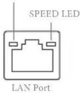
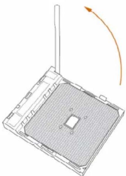
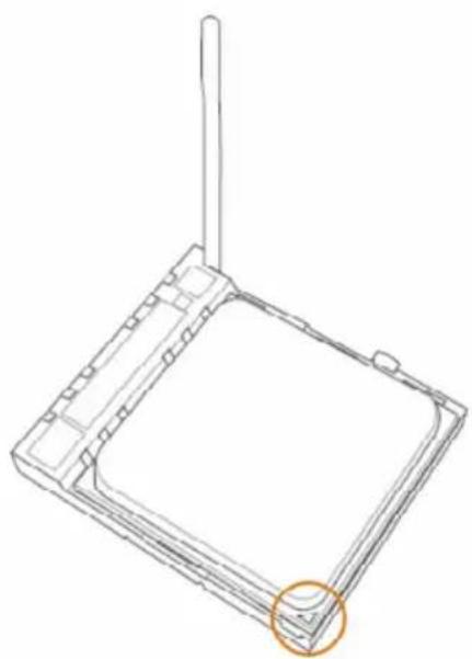
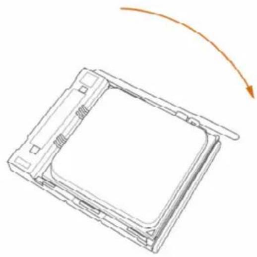
2.1 Installing the CPU

Unplug all power cables before installing the CPU.
1
natural_image
Diagram of a square electronic device with a central square and antenna, showing an orange curved arrow indicating rotation or movement (no text or symbols present)2
natural_image
Technical line drawing of a square electronic component with a vertical rod and circular highlight (no text or symbols)3
natural_image
Diagram of a rectangular device with a curved arrow indicating rotation or movement (no text or symbols)2.2 Installing the CPU Fan and Heatsink
After you install the CPU into this motherboard, it is necessary to install a larger heatsink and cooling fan to dissipate heat. You also need to spray thermal grease between the CPU and the heatsink to improve heat dissipation. Make sure that the CPU and the heatsink are securely fastened and in good contact with each other.

Please turn off the power or remove the power cord before changing a CPU or heatsink.
Installing the CPU Box Cooler SR1
1
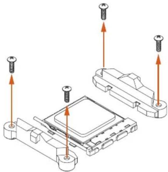
natural_image
Technical diagram showing screw installation on a microchip base (no text or symbols)2
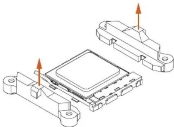
natural_image
Technical line drawing of an electronic component with two housing parts and orange arrows indicating assembly or movement (no text or symbols)3
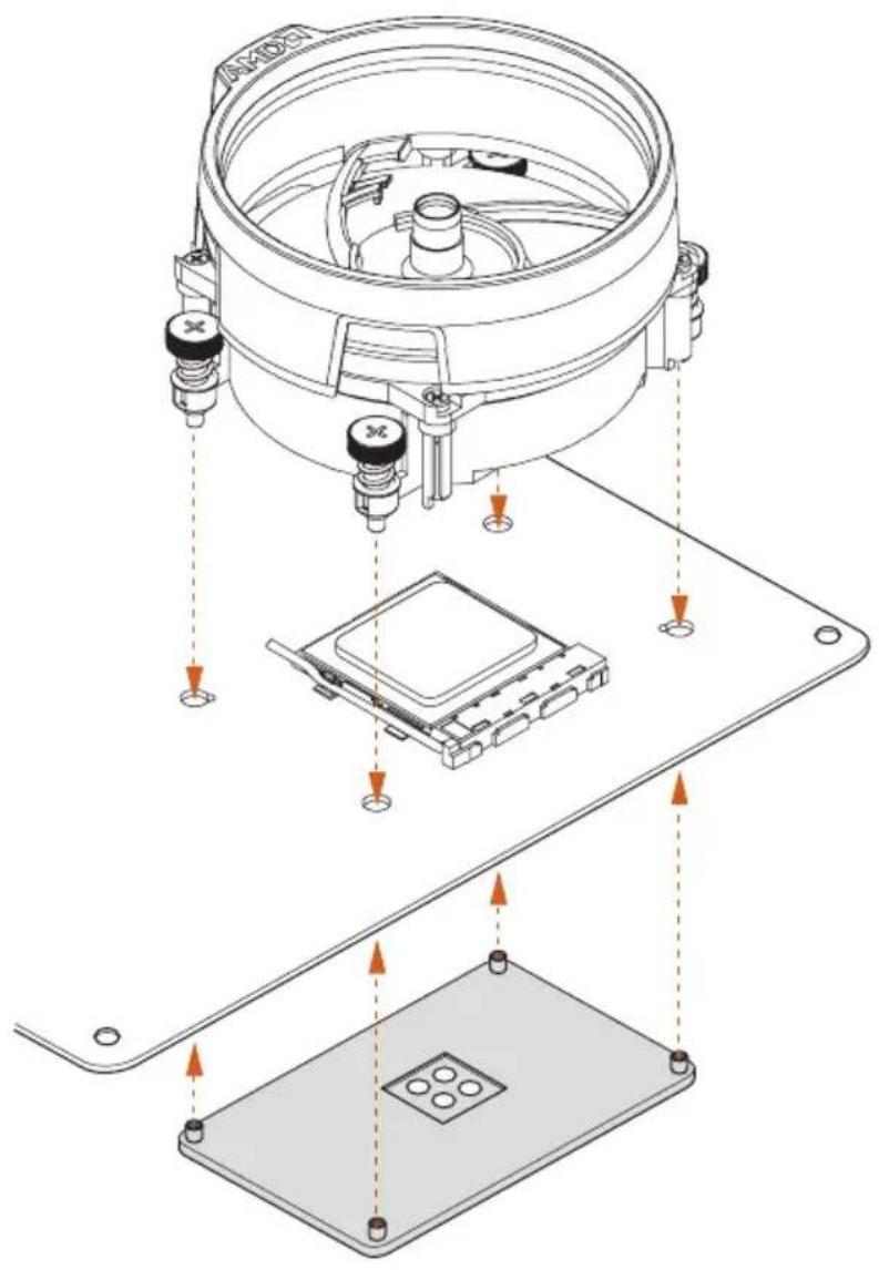
4
natural_image
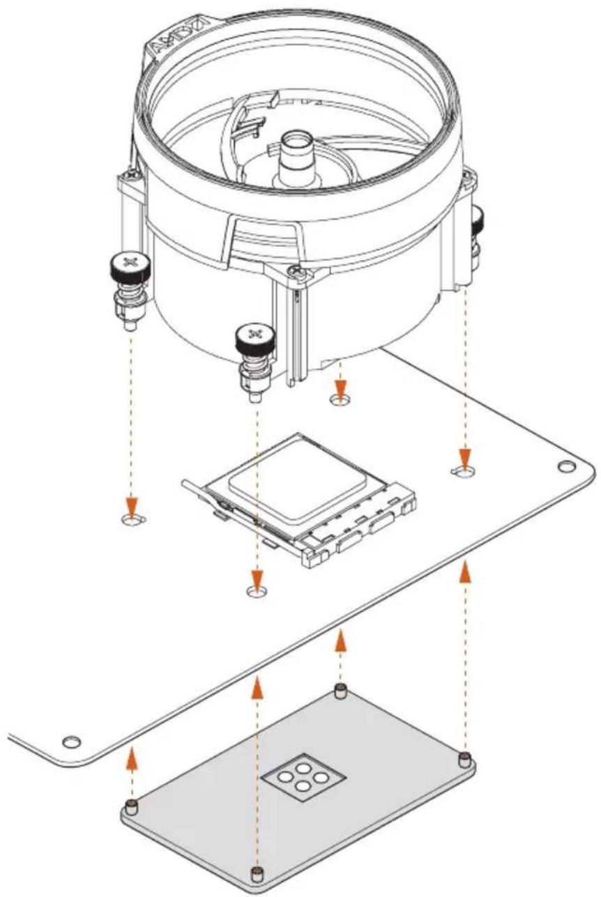
Technical line drawing of a mechanical device with mounting base and wiring, no visible text or symbolsInstalling the AM4 Box Cooler SR2
1
natural_image
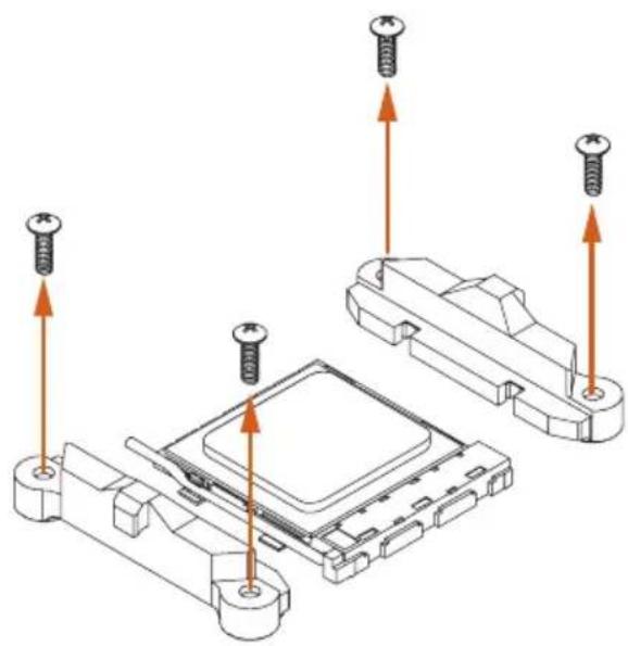
Technical diagram showing screw fasteners inserted into a microchip assembly (no text or labels)2
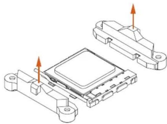
natural_image
Technical line drawing of an electronic component with two views (top and side), showing internal structure and mounting points (no text or symbols)3
4

natural_image
Technical line drawing of a mechanical device with mounting base and wiring, no visible text or symbols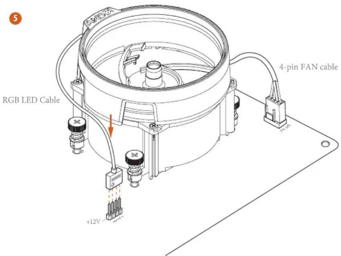
*The diagrams shown here are for reference only. The headers might be in a different position on your motherboard. Please refer to page 35 for the orientation of AMD Fan LED Header (AMD_FAN_LED1).
Installing the AM4 Box Cooler SR3
1
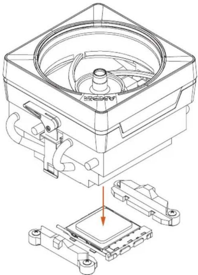
natural_image
Technical line drawing of a mechanical assembly with a central component and two supporting components (no text or symbols)2
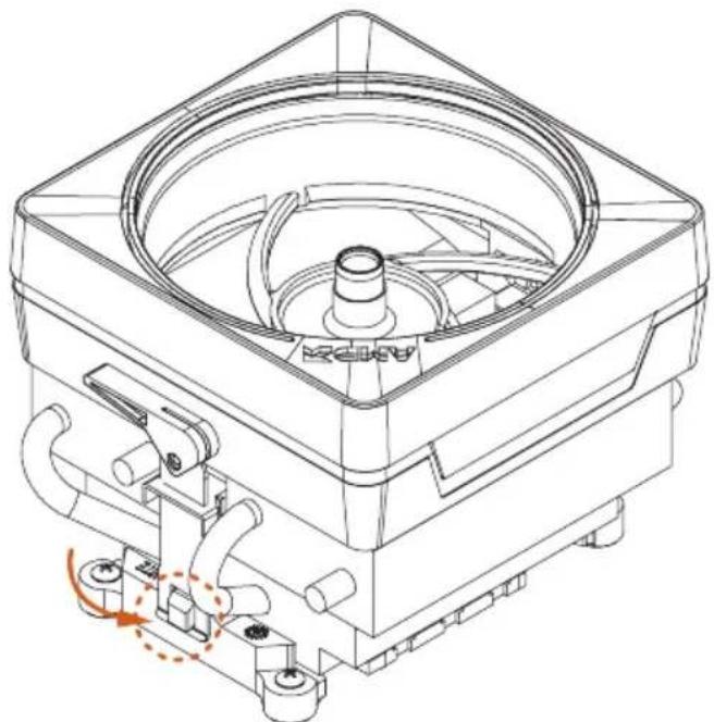
natural_image
Technical line drawing of a mechanical device with no visible text or symbols3
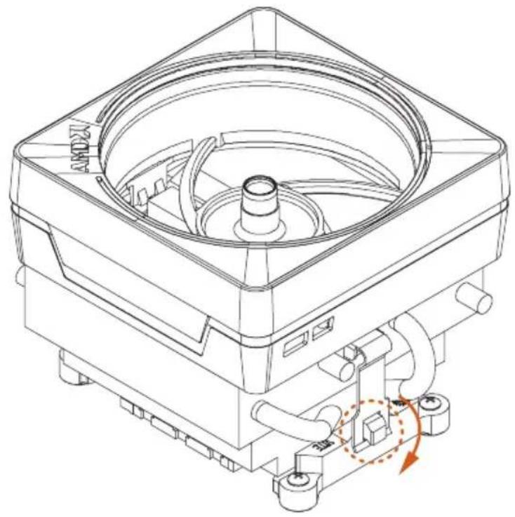
natural_image
Technical line drawing of a mechanical device with no visible text or symbols4
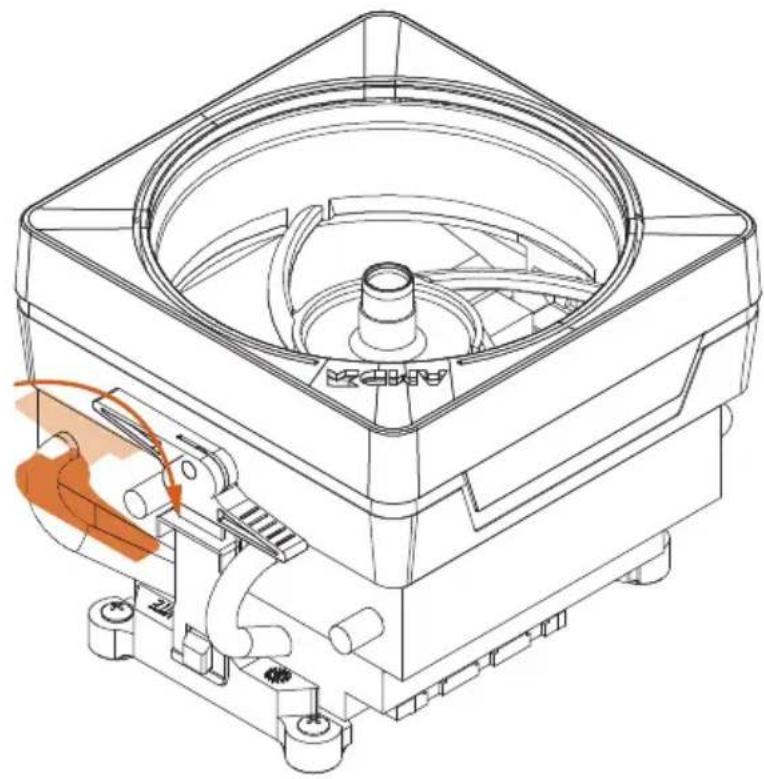
natural_image
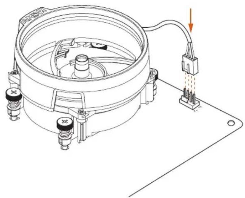
Technical line drawing of a mechanical device with internal components and a highlighted orange section (no text or symbols)5
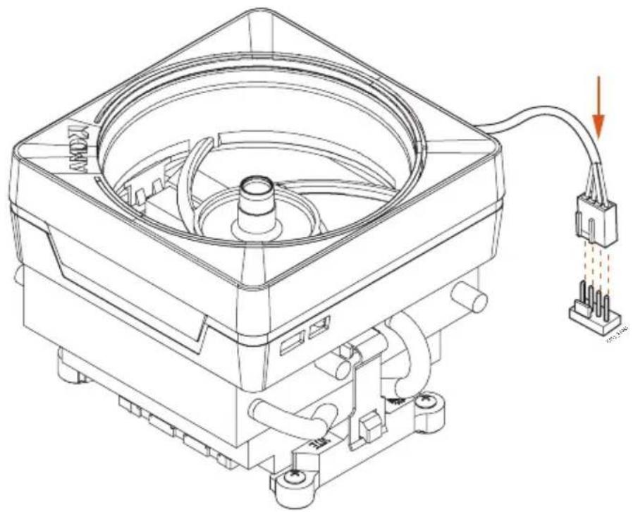
natural_image
Technical line drawing of a mechanical device with internal components and a power connector (no text or symbols)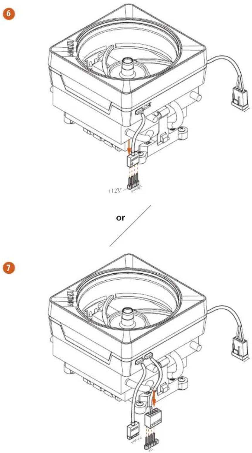
Please note that only one cable should be used at a time in this step.
If you select AMD_FAN_LED1, please install ASRock utility "ASRock Polychrome SYNC".
If you select USB connector, please install AMD utility "SR3 Settings Software".
*The diagrams shown here are for reference only. The headers might be in a different position on your motherboard. Please refer to page 35 for the orientation of AMD Fan LED Header (AMD_FAN_LED1) and page 31 for the orientation of AMD LED Fan USB Header (USB_5).
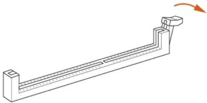
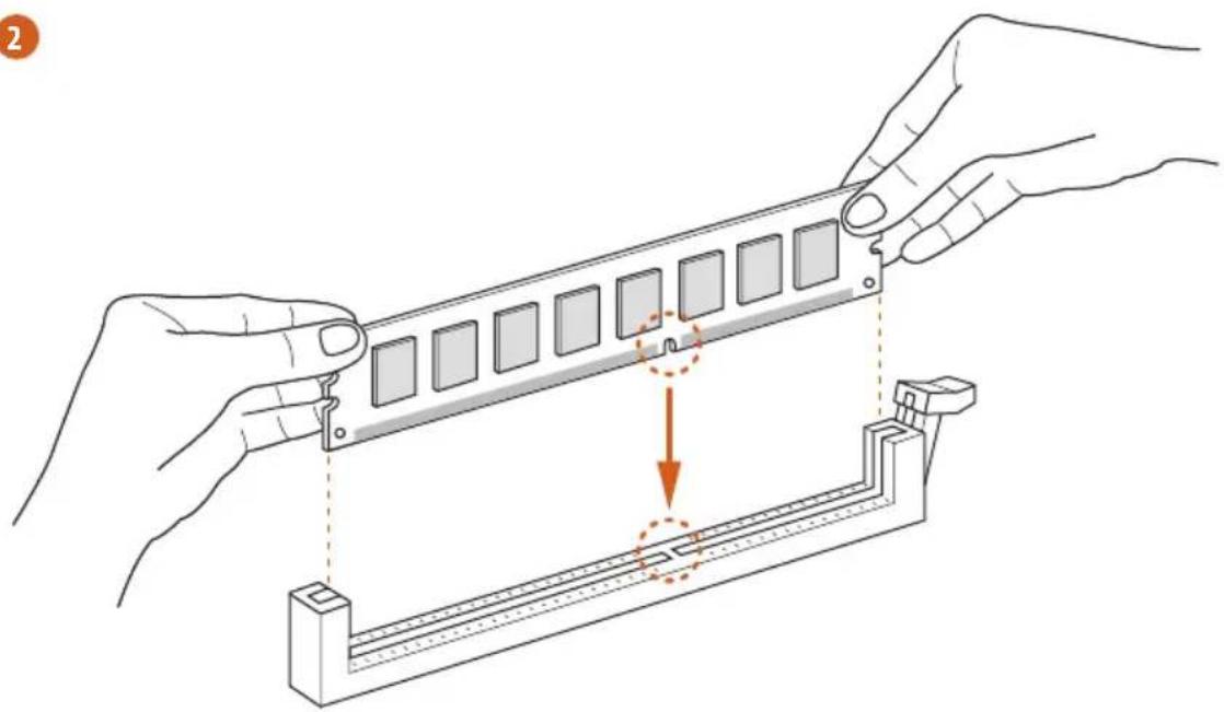
2.3 Installing Memory Modules (DIMM)
This motherboard provides four 288-pin DDR4 (Double Data Rate 4) DIMM slots, and supports Dual Channel Memory Technology.

- For dual channel configuration, you always need to install identical (the same brand, speed, size and chip-type) DDR4 DIMM pairs.
- It is unable to activate Dual Channel Memory Technology with only one or three memory module installed.
- It is not allowed to install a DDR, DDR2 or DDR3 memory module into a DDR4 slot; otherwise, this motherboard and DIMM may be damaged.
- We suggest that you install the memory modules on DDR4_A2 and DDR4_B2 first for better DRAM compatibility on 2 DIMMs configuration.
AMD non-XMP Memory Frequency Support
Ryzen Series CPUs (Matisse):
| UDIMM Memory Slot | Frequency(Mhz) | |||
| A1 | A2 | B1 | B2 | |
| - | SR | - | 3200 | |
| - | DR | - | 3200 | |
| - | SR | - | SR 3200 | |
| - | DR | - | DR 3200 | |
| SR | SR | SR | SR 2933 | |
| SR/DR | DR | SR/DR | DR | 2667 |
| SR/DR | SR/DR | SR/DR | SR/DR | 2667 |
Ryzen Series CPUs (Pinnacle Ridge):
| UDIMM Memory Slot | Frequency(Mhz) | |||
| A1 A2 B1 B2 | ||||
| - SR - - | 2933 | |||
| - DR - - | 2933 | |||
| - SR - SR 2933 | ||||
| - DR - DR 2933 | ||||
| SR SR | SR SR 2933 | |||
| SR/DR DR SR/DR DR | 2667 | |||
| SR/DR | SR/DR | SR/DR | SR/DR | 2133-2400 |
Ryzen Series CPUs (Picasso):
| UDIMM/SO-DIMMs Memory Slot | ||
| # of DIMMs on the Channel | # of Ranks per DIMM | 1.20V |
| 1 of 1 xR | SR: 2933 | |
| DR: 2677 | ||
| 1 of 2 xR-0 | SR: 2667 | |
| DR: 2400 | ||
| 2 of 2 1R-1R 2133 | ||
| 2 of 2 2R-xR 1866 | ||
x=1 or 2
SR: Single rank DIMM, 1Rx4 or 1Rx8 on DIMM module label
DR: Dual rank DIMM, 2Rx4 or 2Rx8 on DIMM module label

The DIMM only fits in one correct orientation. It will cause permanent damage to the motherboard and the DIMM if you force the DIMM into the slot at incorrect orientation.
1
natural_image
Technical line drawing of a mechanical support structure with an arrow indicating rotation (no text or symbols)2
natural_image
Illustration of hands assembling a mechanical component with a highlighted section (no text or symbols)3

natural_image
Isometric line drawing of a rectangular mechanical component with multiple square slots and a curved arrow indicating rotation (no text or symbols)2.4 Expansion Slots (PCI Express Slots)
There are 5 PCI Express slots on the motherboard.

Before installing an expansion card, please make sure that the power supply is switched off or the power cord is unplugged. Please read the documentation of the expansion card and make necessary hardware settings for the card before you start the installation.
PCIe slots:
PCIE1 (PCIe 4.0 x16 slot) is used for PCI Express x16 lane width graphics cards. PCIE2 (PCIe 4.0 x1 slot) is used for PCI Express x1 lane width cards. PCIE3 (PCIe 4.0 x1 slot) is used for PCI Express x1 lane width cards. PCIE4 (PCIe 4.0 x16 slot) is used for PCI Express x4 lane width graphics cards. PCIE5 (PCIe 4.0 x1 slot) is used for PCI Express x1 lane width cards.
PCIe Slot Configurations
PCIE1 PCIE4
Ryzen Series CPUs (Matisse) Gen4x16 Gen4x4
Ryzen Series CPUs (Pinnacle Ridge) Gen3x16 Gen3x4
Ryzen Series CPUs (Picasso) Gen3x8 Gen3x4

For a better thermal environment, please connect a chassis fan to the motherboard's chassis fan connector (CHA_FAN1/WP, CHA_FAN2/WP, CHA_FAN3/WP or CHA_FAN4/WP) when using multiple graphics cards.
2.5 Jumpers Setup
The illustration shows how jumpers are setup. When the jumper cap is placed on the pins, the jumper is “Short”. If no jumper cap is placed on the pins, the jumper is “Open”.

Short

Open
Clear CMOS Jumper
(CLRCMOS1)
(see p.1, No. 23)

2-pin Jumper
Short: Clear CMOS
Open: Default
CLRCMOS1 allows you to clear the data in CMOS. The data in CMOS includes system setup information such as system password, date, time, and system setup parameters. To clear and reset the system parameters to default setup, please turn off the computer and unplug the power cord, then use a jumper cap to short the pins on CLRCMOS1 for 3 seconds. Please remember to remove the jumper cap after clearing the CMOS. If you need to clear the CMOS when you just finish updating the BIOS, you must boot up the system first, and then shut it down before you do the clear-CMOS action.
2.6 Onboard Headers and Connectors

Onboard headers and connectors are NOT jumpers. Do NOT place jumper caps over these headers and connectors. Placing jumper caps over the headers and connectors will cause permanent damage to the motherboard.
System Panel Header (9-pin PANEL1) (see p.1, No. 18)
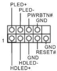
Connect the power button, reset button and system status indicator on the chassis to this header according to the pin assignments below. Note the positive and negative pins before connecting the cables.

PWRBTN (Power Button):
Connect to the power button on the chassis front panel. You may configure the way to turn off your system using the power button.
RESET (Reset Button):
Connect to the reset button on the chassis front panel. Press the reset button to restart the computer if the computer freezes and fails to perform a normal restart.
PLED (System Power LED):
Connect to the power status indicator on the chassis front panel. The LED is on when the system is operating. The LED keeps blinking when the system is in S1/S3 sleep state. The LED is off when the system is in S4 sleep state or powered off (S5).
HDLED (Hard Drive Activity LED):
Connect to the hard drive activity LED on the chassis front panel. The LED is on when the hard drive is reading or writing data.
The front panel design may differ by chassis. A front panel module mainly consists of power button, reset button, power LED, hard drive activity LED, speaker and etc. When connecting your chassis front panel module to this header, make sure the wire assignments and the pin assignments are matched correctly.
Power LED and Speaker Header
(7-pin SPK_PLED1)
(see p.1, No. 19)
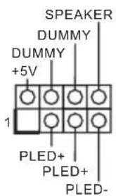
Please connect the chassis power LED and the chassis speaker to this header.
Serial ATA3 Connectors
(SATA3_1_2:
see p.1, No. 13)
(SATA3_3_4:
see p.1, No. 14)
(SATA3_5_6:
see p.1, No. 15)
(SATA3_7_8:
see p.1, No. 16)
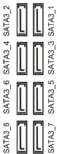
These eight SATA3 connectors support SATA data cables for internal storage devices with up to 6.0 Gb/s data transfer rate.
AMD LED Fan USB
Header
(4-pin USB_5)
(see p.1, No. 31)
This header is used for connecting the USB connector on the AMD SR3 Heatsink.
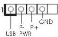
USB 2.0 Headers
(9-pin USB_1_2)
(see p.1, No. 21)
(9-pin USB_3_4)
(see p.1, No. 20)
There are two headers on this motherboard. Each USB 2.0 header can support two ports.
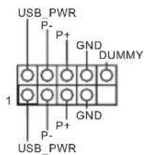
USB 3.2 Gen1 Headers
(19-pin USB3_7_8)
(see p.1, No. 10)
(19-pin USB3_9_10)
(see p.1, No. 9)
There are two headers on this motherboard. Each USB 3.2 Gen1 header can support two ports.
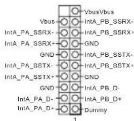
Front Panel Type C USB 3.2 Gen1 Header (20-pin F_USB31_TC_1) (see p.1, No. 17)
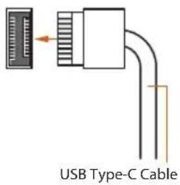
There is one Front Panel Type C USB 3.2 Gen1 Header on this motherboard. This header is used for connecting a USB 3.2 Gen1 module for additional USB 3.2 Gen1 ports.
Front Panel Audio Header (9-pin HD_AUDIO1) (see p.1, No. 30)
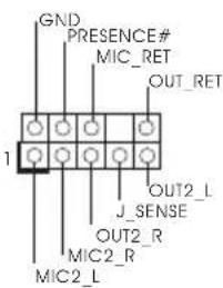
This header is for connecting audio devices to the front audio panel.

- High Definition Audio supports Jack Sensing, but the panel wire on the chassis must support HDA to function correctly. Please follow the instructions in our manual and chassis manual to install your system.
- If you use an AC'97 audio panel, please install it to the front panel audio header by the steps below:
A. Connect Mic_IN (MIC) to MIC2_L.
B. Connect Audio_R (RIN) to OUT2_R and Audio_L (LIN) to OUT2_L.
C. Connect Ground (GND) to Ground (GND).
D. MIC_RET and OUT_RET are for the HD audio panel only. You don't need to connect them for the AC'97 audio panel.
E. To activate the front mic, go to the "FrontMic" Tab in the Realtek Control panel and adjust "Recording Volume".
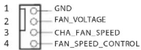
Chassis Water Pump Fan Connectors
(4-pin CHA_FAN1/WP) (see p.1, No. 32)
(4-pin CHA_FAN2/WP) (see p.1, No. 26)
(4-pin CHA_FAN3/WP) (see p.1, No. 22)
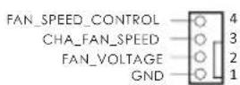

This motherboard provides four 4-Pin water cooling chassis fan connectors. If you plan to connect a 3-Pin chassis water cooler fan, please connect it to Pin 1-3.
(4-pin CHA_FAN4/WP)
(see p.1, No. 12)
CPU Fan Connector
(4-pin CPU_FAN1)
(see p.1, No. 3)
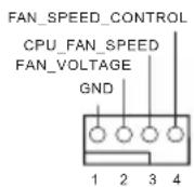
This motherboard provides a 4-Pin CPU fan (Quiet Fan) connector. If you plan to connect a 3-Pin CPU fan, please connect it to Pin 1-3.
CPU Water Pump Fan
Connector
(4-pin CPU_FAN2/WP)
(see p.1, No. 4)
This motherboard provides a 4-Pin water cooling CPU fan connector. If you plan to connect a 3-Pin CPU water cooler fan, please connect it to Pin 1-3.
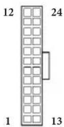
ATX Power Connector
(24-pin ATXPWR1)
(see p.1, No. 8)
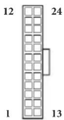
This motherboard provides a 24-pin ATX power connector. To use a 20-pin ATX power supply, please plug it along Pin 1 and Pin 13.
ATX 12V Power
Connector
(8-pin ATX12V1)
(see p.1, No. 1)
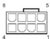
This motherboard provides an 8-pin ATX 12V power connector. To use a 4-pin ATX power supply, please plug it along Pin 1 and Pin 5.
*Warning: Please make sure that the power cable connected is for the CPU and not the graphics card. Do not plug the PCIe power cable to this connector.
ATX 12V Power Connector (4-pin ATX12V2) (see p.1, No. 2)
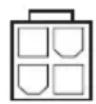
Please connect an ATX 12V power supply to this connector.
*The power supply plug fits into this connector in only one orientation.
Thunderbolt AIC Connector (5-pin TB1) (see p.1, No. 28)

Please connect a Thunderbolt™ add-in card (AIC) to the Thunderbolt AIC connector via the GPIO cable.
*Please install the Thunderbolt™ AIC card to PCIE4 (default slot).
LPC/TPM Header (17-pin TPMS1) (see p.1, No. 29)
This connector supports Trusted Platform Module (TPM) system, which can securely store keys, digital certificates, passwords, and data. A TPM system also helps enhance network security, protects digital identities, and ensures platform integrity.
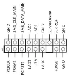
SPI TPM Header (13-pin SPI_TPM_J1) (see p.1, No. 11)
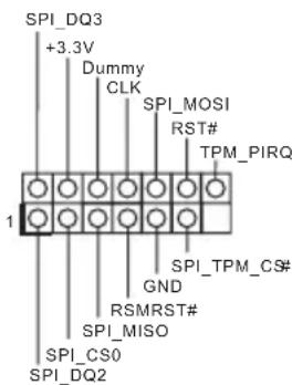
This connector supports SPI Trusted Platform Module (TPM) system, which can securely store keys, digital certificates, passwords, and data. A TPM system also helps enhance network security, protects digital identities, and ensures platform integrity.
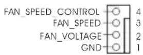
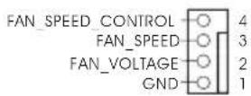
| AMD FAN LED Header(4-pin AMD_FAN_LED1)(see p.1, No. 7) | 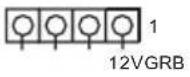 | AMD FAN LED Header is used to connect RGB LED extension cable that comes with AMD heatsink. The cable connection allows users to choose from various LED lighting effects.*The AMD Fan LED Header is compatible with a regular RGB LED stripe.Caution: Never install the FAN LED cable in the wrong orientation; otherwise, the cable may be damaged. |
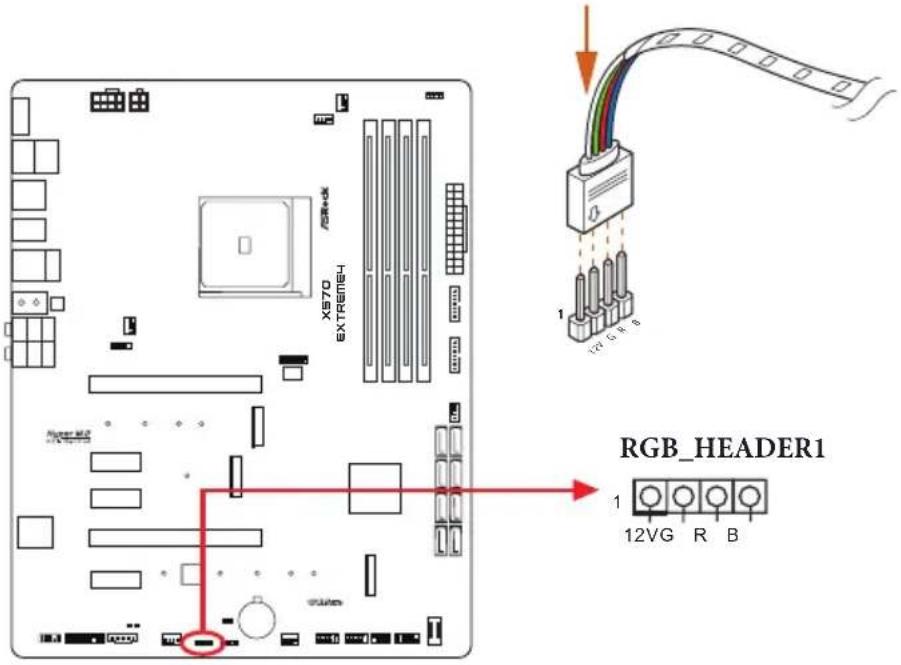
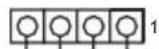
| RGB LED Header(4-pin RGB_HEADER1)(see p.1, No. 25) | 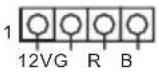 | This RGB header is used to connect RGB LED extension cable which allows users to choose from various LED lighting effects.Caution: Never install the RGB LED cable in the wrong orientation; otherwise, the cable may be damaged.*Please refer to page 45 for further instructions on this header. |
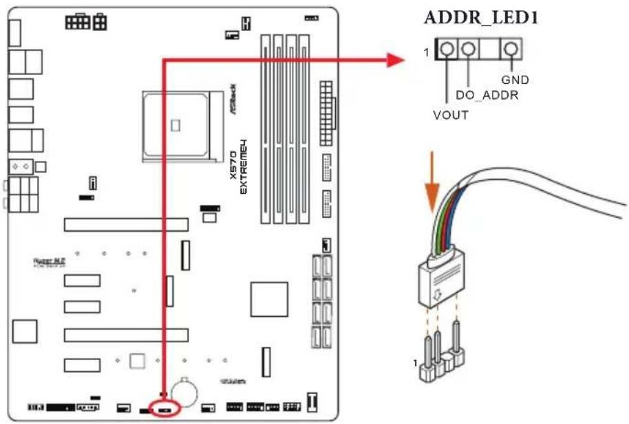
| Addressable LED Header(3-pin ADDR_LED1)(see p.1, No. 24) | 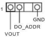 | This header is used to connect Addressable LED extension cable which allows users to choose from various LED lighting effects.Caution: Never install the Addressable LED cable in the wrong orientation; otherwise, the cable may be damaged.*Please refer to page 46 for further instructions on this header. |
2.7 Post Status Checker
Post Status Checker (PSC) diagnoses the computer when users power on the machine. It emits a red light to indicate whether the CPU, memory, VGA or storage is dysfunctional. The lights go off if the four mentioned above are functioning normally.
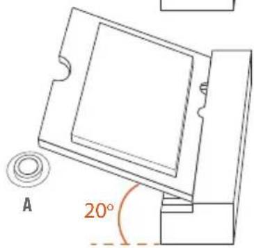
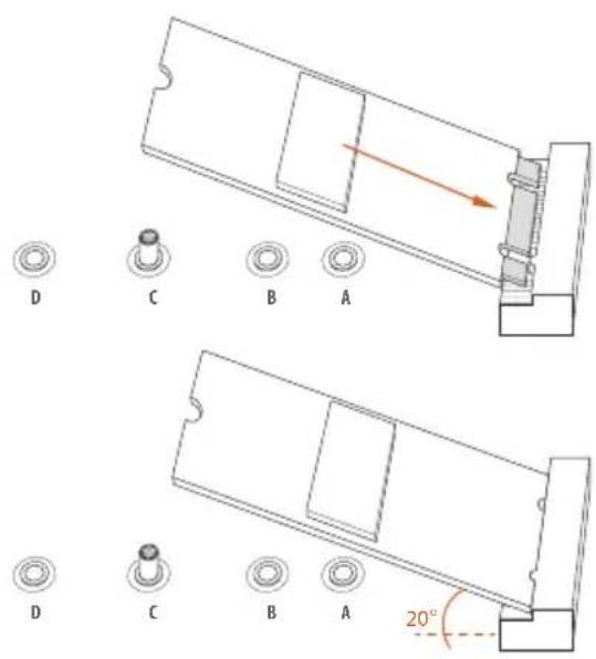
2.8 M.2 WiFi/BT Module Installation Guide
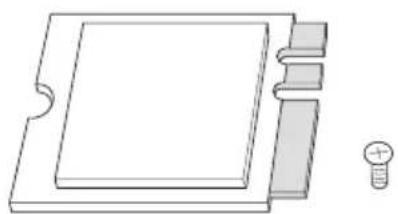
The M.2 Socket (Key E) supports type 2230 WiFi/BT module.
Installing the WiFi/BT module
natural_image
Pure technical line drawing of a mechanical component with no text or symbolsStep 1
Prepare a type 2230 WiFi/BT module and the screw.
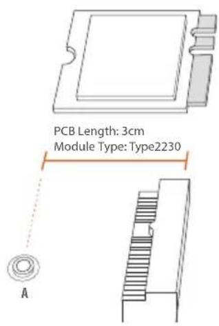
Step 2
Find the nut location to be used.
natural_image
Technical diagram of a mechanical assembly with labeled component A, showing internal components and directional arrow (no text or symbols beyond label)Step 3
Align and gently insert the WiFi/BT module into the M.2 slot. Please be aware that the module only fits in one orientation.
natural_image
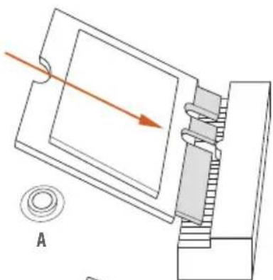
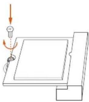
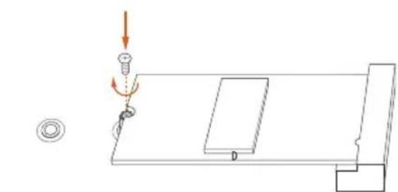
Diagram of a mechanical setup with a spring-loaded component and a curved arm, no text or symbols presentStep 4
Tighten the screw with a screwdriver to secure the module into place. Please do not overtighten the screw as this might damage the module.
2.9 M.2\_SSD (NGFF) Module Installation Guide (M2\_1)
The M.2, also known as the Next Generation Form Factor (NGFF), is a small size and versatile card edge connector that aims to replace mPCIe and mSATA. The M.2 Socket (M2_2) supports M Key type 2230/2242/2260/2280 M.2 PCI Express module up to Gen4x4 (64 Gb/s) (with Matisse) or Gen3x4 (32 Gb/s) (with Pinnacle Ridge and Picasso).
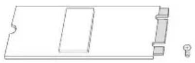
Installing the M.2\_SSD (NGFF) Module
natural_image
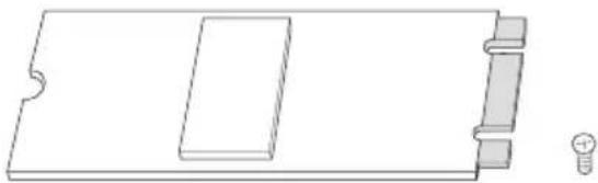
Pure technical line drawing of a rectangular component with internal cutouts and a small protrusion (no text or symbols)Step 1
Prepare a M.2_SSD (NGFF) module and the screw.
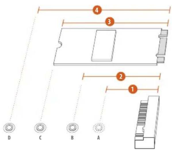
Step 2
Depending on the PCB type and length of your M.2_SSD (NGFF) module, find the corresponding nut location to be used.
No.1234
| Nut Location A B C D | ||||
| PCB Length | 3cm | 4.2cm | 6cm | 8cm |
| Module Type | Type2230 | Type 2242 | Type2260 | Type 2280 |

Step 3
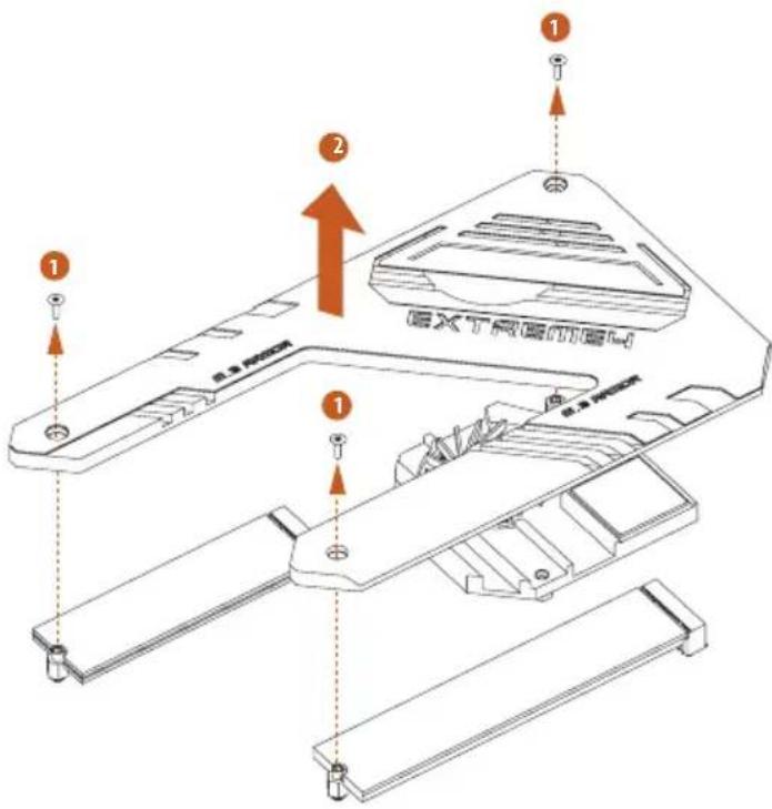
Before installing a M.2 (NGFF) SSD module, please loosen the screws to remove the M.2 heatsink.
*Please remove the protective films on the bottom side of the M.2 heatsink before you install a M.2 SSD module.
Step 4
Prepare the M.2 standoff that comes with the package. Then hand tighten the standoff into the desired nut location on the motherboard. Align and gently insert the M.2 (NGFF) SSD module into the M.2 slot. Please be aware that the M.2 (NGFF) SSD module only fits in one orientation.
natural_image
Pure technical diagram showing a mechanical assembly with no text, numbers, or symbolsStep 5
Tighten the screw with a screwdriver to secure the module into place. Please do not overtighten the screw as this might damage the module.
M.2\_SSD (NGFF) Module Support List
| Vendor Interface P/N |
| SanDisk PCIe SanDisk-SD6PP4M-128G( Gen2 x2) |
| Intel PCIe INTEL 6000P-SSDPEKKF256G7 (nvme) |
| Intel PCIe INTEL 6000P-SSDPEKKF512G7 (nvme) |
| Intel PCIe SSDPEKKF512G7 NVME / 512GB |
| Kingston PCIe Kingston SHPM2280P2 / 240G (Gen2 x4) |
| Samsung PCIe Samsung XP941-MZHPU512HCGL(Gen2x4) |
| Samsung PCIe SM951 (NVME) / 512GB |
| Samsung PCIe SM951 (MZHPV512HDGL) / 512GB |
| ADATA PCIe ASX8000NP-512GM-C / 512GB |
| ADATA PCIe ASX7000NP-512GT-C / 512GB |
| Kingston PCIe SKC1000/480G |
| Kingston PCIe SKC1000/960GB NVME |
| PLEXTOR PCIe PX-512M8PeG/ 512GB |
| WD PCIe WDS512G1X0C-00ENX0 (NVME) / 512GB |
For the latest updates of M.2_SSD (NFGG) module support list, please visit our website for details: http://www.asrock.com
2.10 M.2\_SSD (NGFF) Module Installation Guide (M2\_2)
The M.2, also known as the Next Generation Form Factor (NGFF), is a small size and versatile card edge connector that aims to replace mPCIe and mSATA. The Hyper M.2 Socket (M2_3) supports M Key type 2230/2242/2260/2280/22110 M.2 SATA3 6.0 Gb/s module and M.2 PCI Express module up to Gen4x4 (64 Gb/s).
Installing the M.2\_SSD (NGFF) Module
natural_image
Pure technical line drawing of a rectangular component with a small light bulb at the bottom right corner (no text or symbols)Step 1
Prepare a M.2_SSD (NGFF) module and the screw.
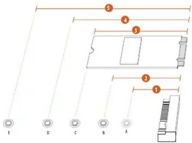
Step 2
Depending on the PCB type and length of your M.2_SSD (NGFF) module, find the corresponding nut location to be used.
No.12345
| Nut Location A B C D E | |||||
| PCB Length | 3cm | 4.2cm | 6cm | 8cm | 11cm |
| Module Type | Type2230 | Type 2242 | Type2260 | Type 2280 | Type 22110 |
Step 3
Before installing a M.2 (NGFF) SSD module, please loosen the screws to remove the M.2 heatsink.
*Please remove the protective films on the bottom side of the M.2 heatsink before you install a M.2 SSD module.

Step 4
Prepare the M.2 standoff that comes with the package. Then hand tighten the standoff into the desired nut location on the motherboard. Align and gently insert the M.2 (NGFF) SSD module into the M.2 slot. Please be aware that the M.2 (NGFF) SSD module only fits in one orientation.
natural_image
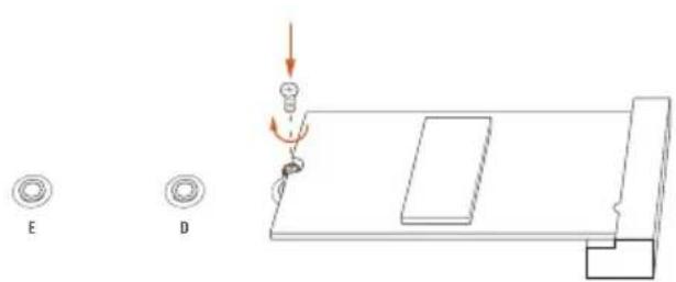
Diagram showing a mechanical assembly with labeled components E and D, no readable text or symbols presentStep 5
Tighten the screw with a screwdriver to secure the module into place. Please do not overtighten the screw as this might damage the module.
M.2\_SSD (NGFF) Module Support List
| Vendor Interface P/N | ||
| SanDisk PCIe SanDisk-SD6PP4M-128G( Gen2 x2) | ||
| Intel PCIe INTEL 6000P-SSDPEKKF256G7 (nvme) | ||
| Intel PCIe INTEL 6000P-SSDPEKKF512G7 (nvme) | ||
| Intel PCIe SSDPEKKF512G7 NVME / 512GB | ||
| Intel SATA 540S-SSDSCKKW240H6 / 240GB | ||
| Kingston PCIe Kingston SHPM2280P2 / 240G (Gen2 x4) | ||
| Samsung PCIe Samsung XP941-MZHPU512HCGL(Gen2x4) | ||
| Samsung PCIe SM951 (NVME) / 512GB | ||
| Samsung PCIe SM951 (MZHPV512HDGL) / 512GB | ||
| ADATA SATA ADATA - AXNS381E-128GM-B | ||
| ADATA PCIe ASX8000NP-512GM-C / 512GB | ||
| ADATA PCIe ASX7000NP-512GT-C / 512GB | ||
| ADATA SATA ASU800NS38-512GT-C / 512GB | ||
| Crucial SATA Crucial-CT240M500SSD4-240GB | ||
| ezlink SATA ezlink P51B-80-120GB | ||
| Intel SATA INTEL 540S-SSDSCKKW240H6-240GB | ||
| Kingston SATA Kingston SM2280S3G2/120G - Win8.1 | ||
| Kingston SATA Kingston-RBU-SNS8400S3 / 180GD | ||
| Kingston PCIe SKC1000/480G | ||
| Kingston PCIe SKC1000/960GB NVME | ||
| LITEON SATA LITEON LJH-256V2G-256GB (2260) | ||
| PLEXTOR SATA PLEXTOR PX-128M6G-2260-128GB | ||
| PLEXTOR SATA PLEXTOR PX-128M7VG-128GB | ||
| PLEXTOR PCIe PX-512M8PeG/ 512GB | ||
| SanDisk SATA SanDisk X400-SD8SN8U-128G | ||
| SanDisk SATA Sandisk Z400s-SD8SNAT-128G-1122 | ||
| SanDisk SATA SanDisk-SD6SN1M-128G | ||
| Transcend SATA Transcend TS256GMTS800-256GB | ||
| Transcend SATA TS512GMTS800 / 512GB | ||
| V-Color SATA V-Color 120G | ||
| V-Color SATA V-Color 240G | ||
| WD SATA WD GREEN WDS240G1G0B-00RC30 | ||
| WD PCIe WDS512G1X0C-00ENX0 (NVME) / 512GB |
For the latest updates of M.2_SSD (NFGG) module support list, please visit our website for details: http://www.asrock.com
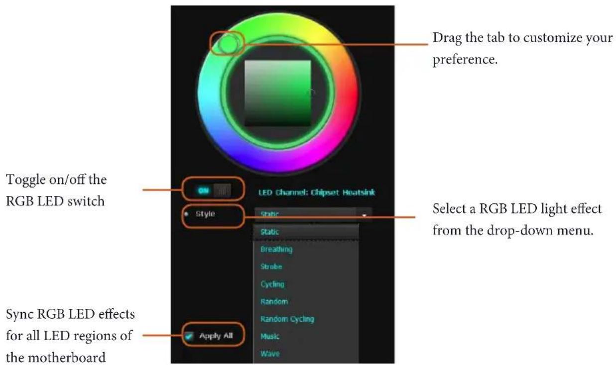
2.11 ASRock Polychrome SYNC
ASRock Polychrome SYNC is a lighting control utility specifically designed for unique individuals with sophisticated tastes to build their own stylish colorful lighting system. Simply by connecting the LED strip, you can customize various lighting schemes and patterns, including Static, Breathing, Strobe, Cycling, Music, Wave and more.
Connecting the LED Strip
Connect your RGB LED strip to the RGB LED Header (RGB_HEADER1) on the motherboard.

- Never install the RGB LED cable in the wrong orientation; otherwise, the cable may be damaged.
- Before installing or removing your RGB LED cable, please power off your system and unplug the power cord from the power supply. Failure to do so may cause damages to motherboard components.

- Please note that the RGB LED strips do not come with the package.
- The RGB LED header supports standard 5050 RGB LED strip (12V/G/R/B), with a maximum power rating of 3A (12V) and length within 2 meters.
Connecting the Addressable RGB LED Strip
Connect your Addressable RGB LED strip to the Addressable LED Header (ADDR_LED1) on the motherboard.

- Never install the RGB LED cable in the wrong orientation; otherwise, the cable may be damaged.
- Before installing or removing your RGB LED cable, please power off your system and unplug the power cord from the power supply. Failure to do so may cause damages to motherboard components.

- Please note that the RGB LED strips do not come with the package.
- The RGB LED header supports WS2812B addressable RGB LED strip (5V/Data/GND), with a maximum power rating of 3A (5V) and length within 2 meters.
ASRock Polychrome SYNC Utility
Now you can adjust the RGB LED color through the ASRock RGB LED utility. Download this utility from the ASRock Live Update & APP Shop and start coloring your PC style your way!
1 Einleitung
(4-polig, CHA_FAN1/WP)
(4-polig, CHA_FAN2/WP)
(4-polig, CHA_FAN3/WP)
(4-polig, CHA_FAN4/WP)
(4-polig, CPU_FAN2/WP)
(siehe S. 1, Nr. 4)
ATX-Netzanschluss
(24-polig, ATXPWR1)
(siehe S. 1, Nr. 8)
• Supporta DTS Connect
LAN
• LAN Gigabit 10/100/1000 Mb/s
• GigaLAN Intel ^® I211AT
• Supporto WOL (Wake-On-LAN)
• Supporto Energy Efficient Ethernet 802.3az
- Supporto PXE
I/O pannello posteriore
- 8 x connettori SATA3 6,0 Gb/s, supporto RAID (RAID 0, RAID 1, e RAID 10), NCQ, AHCI e Hot Plug
- 1 x socket Hyper M.2 (M2_1), supporta il modulo M.2 PCI Express di tipo M Key 2230/2242/2260/2280 fino a Gen4 x4 (64 Gb/s)(con Matisse) o Gen3 x4 (32 Gb/s) (con Pinnacle Ridge e Picasso)*
- 1 x socket Hyper M.2 (M2_2), supporta il modulo M.2 SATA3 6,0 Gb/s di tipo 2230/2242/2260/2280/22110 ed il modulo M.2 PCI Express fino a Gen4 x4 (64 Gb/s)*
* Supporta kit ASRock U.2
Connettore
• Supporta "Plug and Play"
• Supporta jumperfree
(CHA_FAN1/WP a 4 pin)
- Suporta jumperfree
- Suporte SMBIOS 2.3
- Multi-ajuste de tensão de CPU, CPU VDDCR_SOC, DRAM, VPPM, PREM VDD_CLDO, PERM VDDCR_SOC, +1,8V, VDDP
Monitor de hard- ware
- Sensor de Temperatura: CPU, CPU/Bomba de Água, Chassi, Ventoinhas para Chassi/Bomba de Água
(4-pin AMD_FAN_LED1)
(請參閱第1頁,編號7)
12VGRB
AMD FAN LED 排針用於連接
AMD 散熱器隨附的 RGB LED
延長線。纜線連接允許使用者
選擇各種 LED 照明效果。
*AMD 風扇 LED 排針相容於一
般的 RGB LED 燈條。
警告:切勿以錯誤方向安裝
FAN LED 纜線,否則纜線可能損壞。
RGB LED 排針
(4-pin RGB_HEADER1)
(請參閱第1頁,編號25)
12VG R B
CPU Seri AMD Ryzen (Pinnacle Ridge)
- 2 x Slot PCI Express 3.0 x16 (satu pada x16 (PCIE1); dua pada x16 (PCIE1)/x4 (PCIE4))*
If you need to contact ASRock or want to know more about ASRock, you're welcome to visit ASRock's website at http://www.asrock.com; or you may contact your dealer for further information. For technical questions, please submit a support request form at https://event.asrock.com/tsd.asp
ASRock Incorporation
2F., No.37, Sec. 2, Jhongyang S. Rd., Beitou District,
Taipei City 112, Taiwan (R.O.C.)
ASRock EUROPE B.V.
Bijsterhuizen 11-11
6546 AR Nijmegen
The Netherlands
Phone: +31-24-345-44-33
Fax: +31-24-345-44-38
ASRock America, Inc.
13848 Magnolia Ave, Chino, CA91710
U.S.A.
Phone: +1-909-590-8308
Fax: +1-909-590-1026
DECLARATION OF CONFORMITY
Per FCC Part 2 Section 2.1077(a)

Responsible Party Name: ASRock Incorporation
Address: 13848 Magnolia Ave, Chino, CA91710
Phone/Fax N o: +1-909-590-8308/+1-909-590-1026
hereby declares that the product
Product Name : Motherboard
Model Number : X570 Extreme4
Conforms to the following specifications:
☒ FCC Part 15, Subpart B, Unintentional Radiators
Supplementary Information:
This device complies with part 15 of the FCC Rules. Operation is subject to the following two conditions: (1) This device may not cause harmful interference, and (2) this device must accept any interference received, including interference that may cause undesired operation.
Representative Person's Name: James
Signature :
Date : May 12, 2017
EU Declaration of Conformity
ASRock®
For the following equipment:
Motherboard
(Product Name)
X570 Extreme4 / ASRock
(Model Designation / Trade Name)
ASRock Incorporation
(Manufacturer Name)
2F., No.37, Sec. 2, Jhongyang S. Rd., Beitou District, Taipei City 112, Taiwan (R.O.C.)
(Manufacturer Address)
EMC — Directive 2014/30/EU (from April 20th, 2016)
□ EN 55022:2010/AC:2011 Class B
EN 55024:2010/A1:2015
EN 55032:2012+AC:2013 Class B
EN 61000-3-3:2013
EN 61000-3-2:2014
□ LVD — Directive 2014/35/EU (from April 20th, 2016)
□ EN 60950-1:2011+ A2:2013 □
EN 60950-1:2006/A12:2011
☒ RoHS — Directive 2011/65/EU
CE marking
(EU conformity marking)
CE
ASRock EUROPE B.V.
(Company Name)
Bijsterhuizen 1111 6546 AR Nijmegen The Netherlands
(Company Address)
Person responsible for making this declaration:

(Name, Surname)
A.V.P
(Position / Title)
July 5, 2019
(Date)
P/N: 15G062166001AK V1.1