
J5040-ITX - Motherboard ASROCK - Free user manual and instructions
Find the device manual for free J5040-ITX ASROCK in PDF.

| Product type | Mini-ITX motherboard |
| Brand | ASRock |
| Model | J5040-ITX |
| Integrated processor | Intel Quad-Core Pentium Silver J5040 (up to 3.2 GHz) |
| Memory socket | 2 x DDR4 SO-DIMM, max 8 GB, 2400/2133 MHz non-ECC |
| Integrated graphics | Intel UHD Graphics 605, up to 800 MHz, triple display |
| Video outputs | 1x D-Sub, 1x DVI-D, 1x HDMI 4K@60Hz |
| Audio | Realtek ALC892, 7.1 channel HD |
| Network | Realtek RTL8111H Gigabit LAN, Wake-on-LAN, PXE |
| Storage | 4x SATA3 6 Gb/s (2x Intel, 2x ASMedia), NCQ, AHCI, Hot Plug |
| Internal connectors | 1x PCIe 2.0 x1, 1x M.2 (E key) for WiFi/BT, 1x COM, 2x USB 2.0, 1x USB 3.2 Gen1 |
| Back panel connectors | 2x PS/2, 1x D-Sub, 1x DVI-D, 1x HDMI, 1x Optical SPDIF, 2x USB 2.0, 2x USB 3.2 Gen1, 1x RJ-45, audio jacks |
| Dimensions | Mini-ITX: 170 x 170 mm (6.7 x 6.7 inches) |
| Weight | Approximately 500 g (without accessories) |
| Required power supply | 24-pin ATX connector, CPU TDP ~10 W |
| Supported operating system | Windows 10 64-bit |
| BIOS | AMI UEFI, graphical interface, Plug and Play, ACPI 5.0 |
| Special features | Solid capacitors, overvoltage protection, ELNA audio |
| Maintenance and cleaning | Use a dry, soft cloth, avoid abrasive products. Disconnect before cleaning. |
| Safety | Avoid electrostatic discharge, handle by the edges. Use in a grounded case. |
| Spare parts and repairability | No user-serviceable parts. Contact ASRock or an authorized technician. |
Frequently Asked Questions - J5040-ITX ASROCK
User questions about J5040-ITX ASROCK
0 question about this device. Answer the ones you know or ask your own.
Ask a new question about this device
Download the instructions for your Motherboard in PDF format for free! Find your manual J5040-ITX - ASROCK and take your electronic device back in hand. On this page are published all the documents necessary for the use of your device. J5040-ITX by ASROCK.
USER MANUAL J5040-ITX ASROCK
Published January 2020
Copyright ©2020 ASRock INC. All rights reserved.
Copyright Notice:
No part of this documentation may be reproduced, transcribed, transmitted, or translated in any language, in any form or by any means, except duplication of documentation by the purchaser for backup purpose, without written consent of ASRock Inc.
Products and corporate names appearing in this documentation may or may not be registered trademarks or copyrights of their respective companies, and are used only for identification or explanation and to the owners' benefit, without intent to infringe.
Disclaimer:
Specifications and information contained in this documentation are furnished for informational use only and subject to change without notice, and should not be constructed as a commitment by ASRock. ASRock assumes no responsibility for any errors or omissions that may appear in this documentation.
With respect to the contents of this documentation, ASRock does not provide warranty of any kind, either expressed or implied, including but not limited to the implied warranties or conditions of merchantability or fitness for a particular purpose.
In no event shall ASRock, its directors, officers, employees, or agents be liable for any indirect, special, incidental, or consequential damages (including damages for loss of profits, loss of business, loss of data, interruption of business and the like), even if ASRock has been advised of the possibility of such damages arising from any defect or error in the documentation or product.

This device complies with Part 15 of the FCC Rules. Operation is subject to the following two conditions:
(1) this device may not cause harmful interference, and
(2) this device must accept any interference received, including interference that may cause undesired operation.
CALIFORNIA, USA ONLY
The Lithium battery adopted on this motherboard contains Perchlorate, a toxic substance controlled in Perchlorate Best Management Practices (BMP) regulations passed by the California Legislature. When you discard the Lithium battery in California, USA, please follow the related regulations in advance.
"Perchlorate Material-special handling may apply, see www.dtsc.ca.gov/hazardouswaste/perchlorate"
AUSTRALIA ONLY
Our goods come with guarantees that cannot be excluded under the Australian Consumer Law. You are entitled to a replacement or refund for a major failure and compensation for any other reasonably foreseeable loss or damage caused by our goods. You are also entitled to have the goods repaired or replaced if the goods fail to be of acceptable quality and the failure does not amount to a major failure. If you require assistance please call ASRock Tel: +886-2-28965588 ext.123 (Standard International call charges apply)
The terms HDMI^* and HDMI High-Definition Multimedia Interface, and the HDMI logo are trademarks or registered trademarks of HDMI Licensing LLC in the United States and other countries.

Motherboard Layout
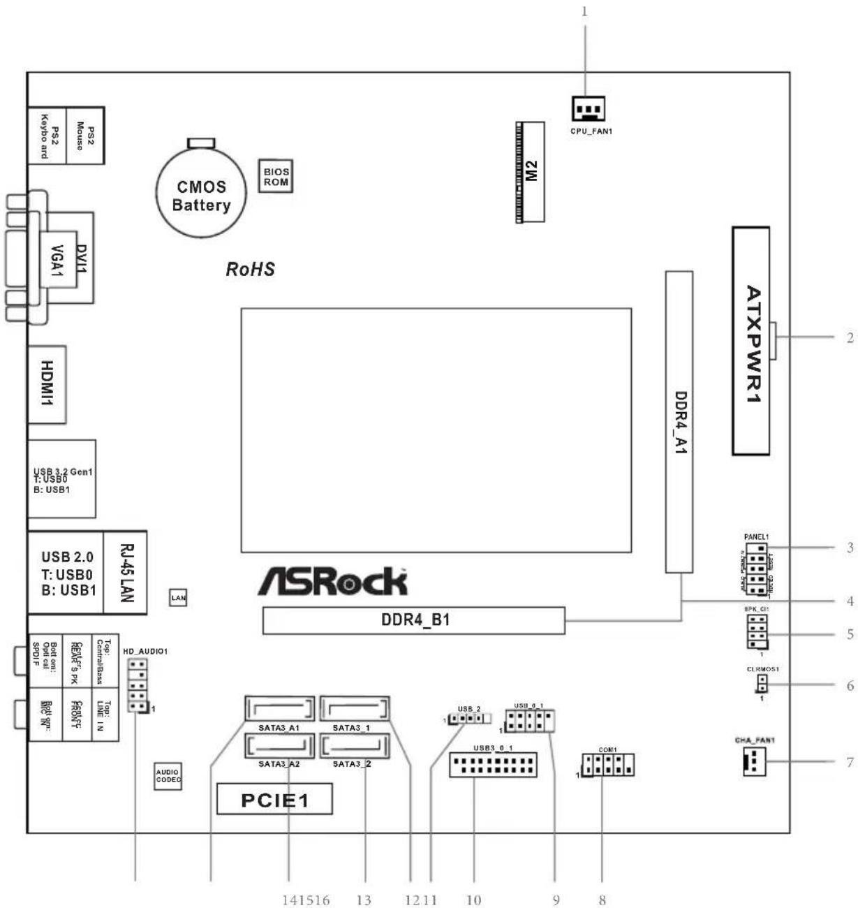
No.Description
1 CPU Fan Connector (CPU_FAN1)
2 ATX Power Connector (ATXPWR1)
3 System Panel Header (PANEL1)
42x260-pin DDR4 SO-DIMM Slots (DDR4_A1, DDR4_B1)
5 Chassis Intrusion and Speaker Header (SPK_C11)
6 Clear CMOS Jumper (CLRMOS1)
7 Chassis Fan Connector (CHA_FAN1)
8 COM Port Header (COM1)
9 USB 2.0 Header (USB_0_1)
10 USB 3.2 Gen1 Header (USB3_0_1)
11 USB 2.0 Header (USB_2)
12 SATA3 Connector (SATA3_1)
13 SATA3 Connector (SATA3_2)
14 SATA3 Connector (SATA3_A2)
15 SATA3 Connector (SATA3_A1)
16 Front Panel Audio Header (HD_AUDIO1)
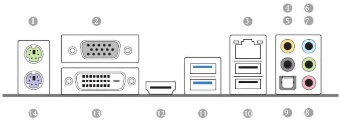
I/O Panel
No.Description No.Description
1 PS/2 Mouse Port 8 Microphone (Pink)
2 D-Sub Port 9 Optical SPDIF Out Port
3 LAN RJ-45 Port 10 USB 2.0 Ports (USB_01)
4 Central / Bass (Orange) 11 USB 3.2 Gen1 Ports (USB3_01)
5 Rear Speaker (Black) 12 HDMI Port
6 Line In (Light Blue) 13 DVI-D Port
7 Front Speaker (Lime)* 14 PS/2 Keyboard Port
- There are two LEDs on each LAN port. Please refer to the table below for the LAN port LED indications.
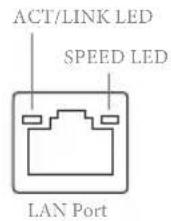
| Activity / Link LED Speed LED | |||
| Status Description Status Description | |||
| Off No Link Off | 10Mbps connection | ||
| Blinking | Data Activity | Orange | 100Mbps connection |
| On Link Green | Gbps connection | ||
** If you use a 2-channel speaker, please connect the speaker's plug into "Front Speaker Jack". See the table below for connection details in accordance with the type of speaker you use.
| Audio Output Channels | Front Speaker (No. 7) | Rear Speaker (No. 5) | Central / Bass (No. 4) | Line In (No. 6) |
| 2 V --- --- | ||||
| 4 V V --- --- | ||||
| 6 V V V --- | ||||
| 8 V V V V |
Chapter 1 Introduction
Thank you for purchasing ASRock J5040-ITX/J4125-ITX motherboard, a reliable motherboard produced under ASRock's consistently stringent quality control. It delivers excellent performance with robust design conforming to ASRock's commitment to quality and endurance.

Because the motherboard specifications and the BIOS software might be updated, the content of this documentation will be subject to change without notice. In case any modifications of this documentation occur, the updated version will be available on ASRock's website without further notice. If you require technical support related to this motherboard, please visit our website for specific information about the model you are using. You may find the latest VGA cards and CPU support list on ASRock's website as well. ASRock website http://www.asrock.com.
1.1 Package Contents
ASRock J5040-ITX/J4125-ITX Motherboard (Mini-ITX Form Factor)
ASRock J5040-ITX/J4125-ITX Quick Installation Guide
- ASRock J5040-ITX/J4125-ITX Support CD
- 2 x Serial ATA (SATA) Data Cables (Optional)
- 1 x I/O Panel Shield
- 1 x Screw for M.2 Socket (Optional)
1.2 Specifications
| Platform | · Mini-ITX Form Factor · Solid Capacitor design |
| CPU | · Intel® Quad-Core Pentium® Silver Processor J5040 (up to 3.2 GHz) (for J5040-ITX) · Intel® Quad-Core Processor J4125 (up to 2.7 GHz) (for J4125-ITX) |
| Memory | · Dual Channel DDR4 Memory Technology · 2 x DDR4 SO-DIMM Slots * 2GB DRAM per module is not supported. · Supports DDR4 2400/2133 non-ECC, un-buffered memory · Max. capacity of system memory: 8GB |
| Expansion Slot | · 1 x PCI Express 2.0 x1 Slot · 1 x M.2 Socket (Key E), supports type 2230 WiFi/BT module and Intel® CNVi (Integrated WiFi/BT) |
| Graphics | · Integrated Intel® UHD Graphics 605: 18 EUs inside (Up to 800MHz) (for J5040-ITX) · Integrated Intel® UHD Graphics 600: 12 EUs inside (Up to 750MHz) (for J4125-ITX) · DX12, OpenGL 4.4, OGL ES 3.1, OpenCL 1.2 · HW Acceleration Decode: HEVC (H.265) 8 bit, HEVC (H.265)10 bit, H.264 @ Lvl5.2 (AVC), JPEG/MJPEG, VP8, VP9 8bit, VP9 10 bit · HW Acceleration Encode: HEVC (H.265) 8 bit, HEVC (H.265)10 bit, H.264 @ Lvl5.2 (AVC), JPEG/MJPEG, VP8, VP9 8bit · Three graphics output options: D-Sub, DVI-D and HDMI · Supports Triple Monitor · Supports HDMI with max. resolution up to 4K x 2K (4096x2160) @ 60Hz · Supports DVI-D with max. resolution up to 1920x1200 @ 60Hz · Supports D-Sub with max. resolution up to 2048x1536 @ 60Hz · Supports Auto Lip Sync, xvYCC and HBR (High Bit Rate Audio) with HDMI Port (Compliant HDMI monitor is required) |
| Supports HDCP 2.2 with DVI-D and HDMI Ports Supports Full HD 1080p Blu-ray (BD) playback with DVI-D and HDMI Ports | |
| Audio | 7.1 CH HD Audio with Content Protection (Realtek ALC892 Audio Codec) Premium Blu-ray Audio support Supports Surge Protection ELNA Audio Caps |
| LAN | PCIEx1 Gigabit LAN 10/100/1000 Mb/s Realtek RTL8111H Supports Wake-On-LAN Supports Lightning/ESD Protection Supports Energy Efficient Ethernet 802.3az Supports PXE |
| Rear Panel I/O | 1 x PS/2 Mouse Port 1 x PS/2 Keyboard Port 1 x D-Sub Port 1 x DVI-D Port 1 x HDMI Port 1 x Optical SPDIF Out Port 2 x USB 2.0 Ports (Supports ESD Protection) 2 x USB 3.2 Gen1 Ports (Supports ESD Protection) 1 x RJ-45 LAN Port with LED (ACT/LINK LED and SPEED LED) HD Audio Jacks: Rear Speaker / Central / Bass / Line in / Front Speaker / Microphone |
| Storage | 2 x SATA3 6.0 Gb/s Connectors, support NCQ, AHCI and Hot Plug 2 x SATA3 6.0 Gb/s Connectors by ASMia ASM1061, support NCQ, AHCI and Hot Plug |
| Connector | 1 x COM Port Header 1 x Chassis Intrusion and Speaker Header 1 x CPU Fan Connector (3-pin) 1 x Chassis Fan Connector (3-pin) 1 x 24 pin ATX Power Connector 1 x Front Panel Audio Connector |
- 2 x USB 2.0 Headers (Support 3 USB 2.0 ports) (Supports ESD Protection)
-
1 x USB 3.2 Gen1 Header (Supports 2 USB 3.2 Gen1 ports) (Supports ESD Protection)
-
USB3_0_1 and USB_0_1 cannot be occupied simultaneously. Please connect a USB cable to one of these headers only.
BIOS
AMI UEFI Legal BIOS with GUI support
Feature
Supports Plug and Play
ACPI 5.0 compliant wake up events
Supports jumperfree
SMBIOS 3.0 support
Hardware
CPU/Chassis temperature sensing
CPU/Chassis Fan Tachometer
- CPU/Chassis Quiet Fan (Auto adjust chassis fan speed by CPU temperature)
CPU/Chassis Fan multi-speed control
CASE OPEN detection
Voltage monitoring: +12V, + 5V, + 3.3V CPU Vcore
os
- Microsoft® Windows® 10 64-bit
Certifica
FCC,CE
tions
ErP/EuP ready (ErP/EuP ready power supply is required)
- For detailed product information, please visit our website: http://www.asrock.com
Chapter 2 Installation
This is a Mini-ITX form factor motherboard. Before you install the motherboard, study the configuration of your chassis to ensure that the motherboard fits into it.
Pre-installation Precautions
Take note of the following precautions before you install motherboard components or change any motherboard settings.
- Make sure to unplug the power cord before installing or removing the motherboard. Failure to do so may cause physical injuries to you and damages to motherboard components.
- In order to avoid damage from static electricity to the motherboard's components, NEVER place your motherboard directly on a carpet. Also remember to use a grounded wrist strap or touch a safety grounded object before you handle the components.
- Hold components by the edges and do not touch the ICs.
- Whenever you uninstall any components, place them on a grounded anti-static pad or in the bag that comes with the components.
- When placing screws to secure the motherboard to the chassis, please do not overtighten the screws! Doing so may damage the motherboard.
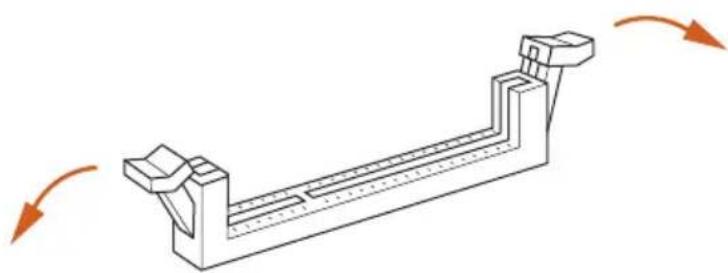
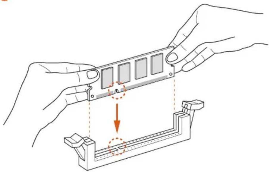
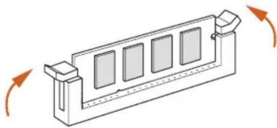
2.1 Installation of Memory Modules (SO-DIMM)
This motherboard provides two 260-pin DDR4 (Double Data Rate 4) SO-DIMM slots, and supports Dual Channel Memory Technology.

- It is not allowed to install a DDR, DDR2 or DDR3 memory module into a DDR4 slot; otherwise, this motherboard and SO-DIMM may be damaged.
- The SO-DIMM only fits in one correct orientation. It will cause permanent damage to the motherboard and the SO-DIMM if you force the SO-DIMM into the slot at incorrect orientation.
Supported DDR4 Non ECC SODIMM
Raw Card
A (1Rx8)
B (2Rx8)
C (1Rx16)
Dual Channel Memory Configuration
DDR4_A1
Populated
DDR4_B1
Populated
1
2
3
2.2 Expansion Slot (PCI Express Slot)
There is 1 PCI Express slot on the motherboard.

Before installing an expansion card, please make sure that the power supply is switched off or the power cord is unplugged. Please read the documentation of the expansion card and make necessary hardware settings for the card before you start the installation.
PCIe slot:
PCIE1 (PCIe 2.0 x1 slot) is used for PCI Express x1 lane width cards.
Warning:
To ensure better graphics compatibility, the BIOS is set to "boot from Onboard VGA" as default even the user install a VGA card on PCIe slot.
2.3 Jumpers Setup
The illustration shows how jumpers are setup. When the jumper cap is placed on the pins, the jumper is "Short". If no jumper cap is placed on the pins, the jumper is "Open".
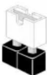
Short
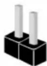
Open
*The jumper cap is not provided.
Clear CMOS Jumper
(CLRCMOS1)
(see p.1, No. 6)

2-pin Jumper
Short: Clear CMOS
Open: Default
CLRCMOS1 allows you to clear the data in CMOS. The data in CMOS includes system setup information such as system password, date, time, and system setup parameters. There are two ways for you to clear and reset the system parameters to the default setup. Please turn off the computer and unplug the power cord, then you may either short the solder points on CLRCMOS1 by using metal material, e.g., a paper clip for 3 seconds; or you may use a jumper cap to short the pin on CLRCMOS1 for 3 seconds. Please remember to remove the paper clip or the jumper cap after clearing the CMOS.

If you clear the CMOS, the case open may be detected. Please adjust the BIOS option "Clear Status" to clear the record of previous chassis intrusion status.
2.4 Onboard Headers and Connectors

Onboard headers and connectors are NOT jumpers. Do NOT place jumper caps over these headers and connectors. Placing jumper caps over the headers and connectors will cause permanent damage to the motherboard.
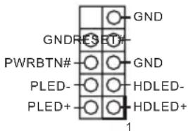
System Panel Header
(9-pin PANEL1)
(see p.1, No. 3)
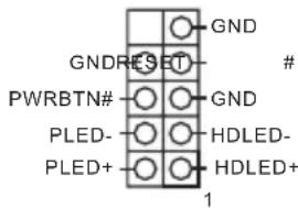
Connect the power button, reset button and system status indicator on the chassis to this header according to the pin assignments below. Note the positive and negative pins before connecting the cables.

PWRBTN (Power Button):
Connect to the power button on the chassis front panel. You may configure the way to turn off your system using the power button.
RESET (Reset Button):
Connect to the reset button on the chassis front panel. Press the reset button to restart the computer if the computer freezes and fails to perform a normal restart.
PLED (System Power LED):
Connect to the power status indicator on the chassis front panel. The LED is on when the system is operating. The LED keeps blinking when the system is in S1/S3 sleep state. The LED is off when the system is in S4 sleep state or powered off (S5).
HDLED (Hard Drive Activity LED):
Connect to the hard drive activity LED on the chassis front panel. The LED is on when the hard drive is reading or writing data.
The front panel design may differ by chassis. A front panel module mainly consists of power button, reset button, power LED, hard drive activity LED, speaker and etc. When connecting your chassis front panel module to this header, make sure the wire assignments and the pin assignments are matched correctly.
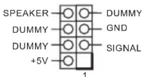
Chassis Intrusion and
Speaker Header
(7-pin SPK_C11)
(see p.1, No. 5)
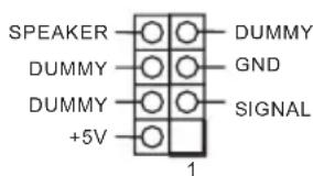
Please connect the chassis intrusion and the chassis speaker to this header.
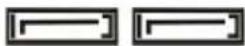
Serial ATA3 Connectors
(SATA3_1:
see p.1, No. 12)
(SATA3_2:
see p.1, No. 13)
(SATA3_A1:
see p.1, No. 15)
(SATA3_A2:
see p.1, No. 14)
SATA3_A1SATA3_1


SATA3_A2SATA3_2
These four SATA3
connectors support SATA
data cables for internal
storage devices with up to
6.0 Gb/s data transfer rate.
- To minimize the boot
time, use Intel® SATA
ports (SATA3_1~2) for
your bootable devices.
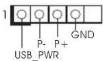
USB 2.0 Headers
(4-pin USB_2)
(see p.1, No. 11)
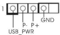
There are two headers on
this motherboard.
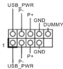
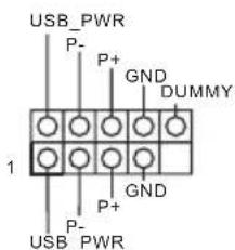
(9-pin USB_0_1)
(see p.1, No. 9)
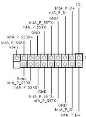
USB 3.2 Gen1 Header
(19-pin USB3_0_1)
(see p.1, No. 10)
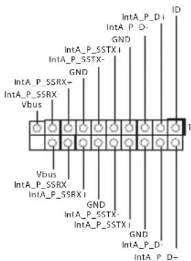
There is one header on
this motherboard. This
USB 3.2 Gen1 header can
support two ports.
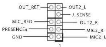
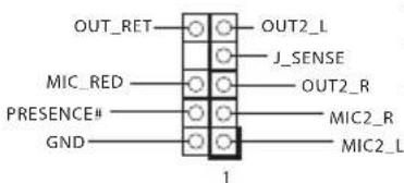
Front Panel Audio Header
(9-pin HD_AUDIO1)
(see p.1, No. 16)
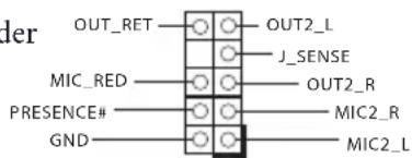
This header is for
connecting audio devices
to the front audio panel.

- High Definition Audio supports Jack Sensing, but the panel wire on the chassis must support HDA to function correctly. Please follow the instructions in our manual and chassis manual to install your system.
- If you use an AC'97 audio panel, please install it to the front panel audio header by the steps below:
A. Connect Mic_IN (MIC) to MIC2_L
B. Connect Audio_R (RIN) to OUT2_R and Audio_L (LIN) to OUT2_L.
C. Connect Ground (GND) to Ground (GND).
D. MIC_RET and OUT_RET are for the HD audio panel only. You don't need to connect them for the AC'97 audio panel.
E. To activate the front mic, go to the "FrontMic" Tab in the Realtek Control panel and adjust "Recording Volume".
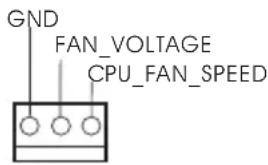
Chassis Fan Connector
(3-pin CHA_FAN1)
(see p.1, No. 7)
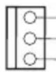
GND
FAN_VOLTAGE
CHA_FAN_SPEED
Please connect fan cable to the fan connector and match the black wire to the ground pin.
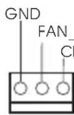
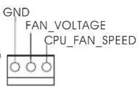
CPU Fan Connector
(3-pinCPU_FAN1)
(see p.1, No. 1)

Please connect the CPU fan cable to the connector and match the black wire to the ground pin.
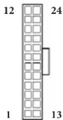
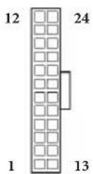
ATX Power Connector
(24-pinATXPWR1)
(see p.1, No. 4)
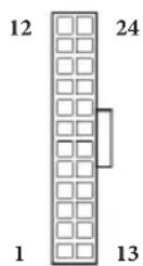
This motherboard provides a 24-pin ATX power connector. To use a 20-pin ATX power supply, please plug it along Pin 1 and Pin 13.
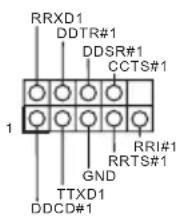
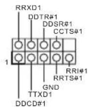
Serial Port Header
(9-pin COM1)
(see p.1, No. 8)
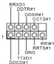
This COM1 header supports a serial port module.
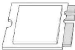
2.5 M.2 WiFi/BT Module and Intel® CNVi (Integrated WiFi/BT) Installation Guide
The M.2, also known as the Next Generation Form Factor (NGFF), is a small size and versatile card edge connector that aims to replace mPCIe and mSATA. The M.2 Socket (Key E) supports type 2230 WiFi/BT module and Intel® CNVi (Integrated WiFi/BT).
- The M.2 socket does not support SATA M.2 SSDs.
Installing the WiFi/BT module
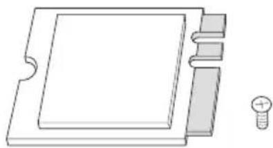
Step 1
Prepare a type 2230 WiFi/BT module or Intel CNVi (Integrated WiFi/BT) and the screw.
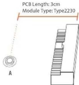
Step 2
Find the nut location to be used.
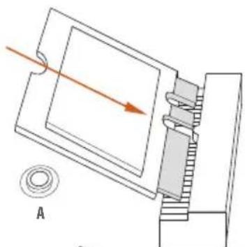
Step 3
Gently insert the WiFi/BT module or Intel® CNVi (Integrated WiFi/ BT) into the M.2 slot. Please be aware that the module only fits in one orientation.
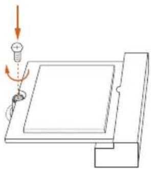
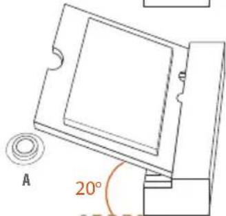
Step 4
Tighten the screw with a screwdriver to secure the module into place. Please do not overtighten the screw as this might damage the module.
1 Einleitung
FCC,CE
- CoBMeCTHMOCTb c ErP/EuP (Heo6XoJIM 6IOK IITaHnI, coOTBeTcTByOII m cTaHApTy ErP/EuP)
^*C dononhumenbho unhfoopmauee ou 3doenu moKHO O3nakomumbcHa 6eb-catme: http://www.asrock.com
1.3 YcTaHOBka nepembIueK
YcTaHOBka IepEmbIueK IOKa3aHa Ha pncyHke. PpN yCTaHOBKe IepEmbUckn-KOJIpaKa Ha KOHTaKTbI IepEmbUka «3aMKHyTa>. EcII IepEmbUka-KOJIpaOK Ha KOHTaKTbI He yCTaHOBJIeHa, IepEmbUka «pa3OMKHyTa>.

Short

Open
KoIOnKa MaTePnHcKoI NaHeJI
(9-KoHTaKTHa, PANEL1) (CM. cTp. 1, No 3)
IoiKIOUHTpe paioIOJKeHHbIE Ha KOpNuce KHOINKpy INTaHn, KHOIKy Iepe3aRpy3KN HINIKKaTOP COCTOHN CnCTeMBI K 3TOI KOIOKe B COOTBeTCTBmC Ha3HaueHHeM KOHTaKTOB, IIpNBdeHHbIM HnKe. Iepei IOIKIOUeHHem Ka6eIe ONPeJIte IOIOXNTbHbI N OTPNuTeHBHKOHTaKtBI.

PWRBTN (khonka numahua):
IioKluuHue Klonku numau, pacnoIoKeHHou ha nepeOneHa neHeu npKopnyca. MoKho hacmpoumb cnocob bblouenua cucmemb npu naKamuu Khonku numau.
RESET (knonka c6poca):
IIOkKnue Hne KhONku c6pOca, pacnoJooKeHHo Ha nepeDHe naneu Kopnyca. Hakmume KhONky c6pOca, umobn nepe3anycnumb Komnbomep, eclu on 3abuc u hopmaNbHn nepe3anyck Hebo3moKeH.
PLED (cbemoduodhui undukamop numanu cucmembl):
Iodkouenue uduukamopacomnna, pacnooncenho na nepehne naneu Kopnyca.
CbeMoDuOdbu unDukamop zoum, Ko2a cUmema paobomaem. Ko2a cUmema haxoumcn b peKume oKudanur S1/S3, cbemoduod muzaem. Ko2a cUmema haxoumcn b peKume oKudanur S4 uuu bkvKnouena (S5), cbemoduo He zoum.
HDLED (cbemoduodhui undukamop paobomj kecmkozo ducka):
Iodkouenue Cbeoduooho unukamopa paobm kecmkoo ducka, pacnoiokeHHO no napeedneu naneu. Cbeoduoohbu unukamop zopum, kozda kecmku duck bbinonnem cuumbiahe uuu 3anucb daHHbx.
Ipeedha naehb moem 6bimb pa3hoHa pa3hix Kopnycax. Ha nepehei naenu pacnoiokehi kHonka numanua, kHonka nepezanycka, undukamop numanu, undukamop paobmb kcimko0 ducka, duhamuk u m.d. Ipu nodknoeenu nepedhu naenu Kmou konodke nodknouaume npooba Ka coombemcmbyuum konhmakmam.
KoIOKa c pa3bEmaMn
IaTUnKa BCKpbITNa KOpIyCa
HINHaMnKa
(7 KOHTaKTbIn, SPK_CI1)
(cM. cTp. 1, N° 5)
IpeHa3HaueHa IJIa IIOKIIIOUeHn JaTtNkA BCKpbITn KOpIyCa n KOpIyCHOrO dHAmKka.
Pa3beMbSerial ATA3
(SATA3_1:
cm. ctp.1, No 12)
(SATA3_2:
cm. ctp.1, N 13)
(SATA3_A1:
cm. ctp.1, No 15)
(SATA3_A2:
cm. crp.1, N 14)
SATA3_A1SATA3_1
SATA3_A2SATA3_2

Tn tbepa bema
SATA3 IIpeHa3NaueHbI IJI
IOIKIIoueHnKa6eIeSATA
BHyTpeHHx 3aIOMHaIOIIHX
yCTPOICTB IJIpePaH
IaHHbIX CO cKOpocTbIO IO 6,0
Γ6nt/c.
*C cieIbIO cokpaIeHnBpeMeHn 3aRpy3Kn HcNoIb3yIte IOpTb1 Intel* SATA (SATA3_1-2) nIra caMo3arpykaembIX yCTpOJCTB.
KoIOkN USB 2.0
(4 KOHTaKaTa, USB_2)
(cM. cTp. 1, N° 11)
Ha MaTePnHcKoI IaTe NMeetCn DBe KOJIOIKN.
(9 KOHTaKTOB, USB_0_1)
(cM.cTp.1,N99)
KoIOdkn USB 3.2 Gen1
(19 KOHTaKTOB, USB3_0_1)
(cm.cTp.1, No 10)
Ha MaTePnHcKoI INaTe HMeetca OHa KOIoKa. 3a KoIoKa USB 3.2 Gen1 IOJIepKuBaET JBa IopTa.
AynokoIoka nepedne IaHei
(9 KOHTAKTOB, HD_AUDIO1
(cM. cTp. 1, N° 16)
3Ta KOIOJa IIpeHa3NaYeHa IJIa IIOKIIoueHnayIIOuOyCTPOIcTB K IpeIHe aYIIOHaHeI.

-
Ayduocumema blicokozopazpeuuehna nodepkubae m fykuuo paonosabaunpa3bema, no dne npabunbnoi pabomtu neobxodmo, umbo npobod naenu kopyca nodepkuaan nepedauy cuenaob HDA. Hncmpykuuu no ycmanobke cucmembu cm. 6omom pykoobcmeu pykoobcme be h Kopnyc.
-
Ipu unnoIb3ObaHuu ayduonanaHenu AC'97 nodkIouyume ee k ayduokoIodke nepedneu naHenu, kaYkaaso danee:
A. Iiokkoume Mic_IN (MIC) κ MIC2_L
B. Hódknquume Audio_R (RIN) κ OUT2_R, Audio_L (LIN) κ OUT2_L.
C.Поdkлουиnm npoobd 3a3emienu(GND)к konmakeya3aemienu(GND).
D. Kohmikbu MIC_RET u OUT_RET ucnolb3yomc monbko dna ayduonanaenu bvcokozopazpeuene. Ipu u cnobn3obauu ayduonaneu AC'97 ux nodknouamb he hykno.
E. Ymobsakmuupoamnb nepedhuu mukpofoh, nepeudume ha bkaadky FrontMic naenu ynpasienue Realtek u ompezynupyime napamemp Recording Volume (Fpomkocmb zanucu).
Pa3bEm BeHTnIaTopa Kopnyca
(3 KOHTaKta, CHA_FAN1) (cm. ctp. 1, No 7)

GND
FAN_VOLTAGE
CHA_FAN_SPEED
IpeHa3HaeH IJIa
IOKIOUeHN Ka6eJa pa3bema
BeHTIOITopa N IOKIOUeHN
YePHOrO IIPOBOJa K
3a3eMJIeHnIO.
Pa3bem BeHTNIJTopa oxJaXeHnI npOeCCopa
(3 KOHTaKa, CPU_FAN1)
(cM. cTp. 1, N° 1)
IpeHa3HaueH I
IOKIOUeHn Ka6eIa
pa3bema BHTnIaTopa III;
YePbI IPOBOI IOJKeH 6bITbIOIKIOUeH K 3a3EmHeHIO.
Pa3bem INTaHnA ATX
(24 KOHTaKa,ATXPR1)
(cM. ctp. 1, N° 4)
Ta MaTePnHcKaI IaTa
OChaIeHa 24-KoHTaKTHbIM
pa3bEMOM IIrTaHnA ATX. YTo6bl
NCIOJIb3OBaTb 20-KoHTaKTHbI
pa3bEm IIITaHnA ATX,
IOIKIIIOuHte eRO BIOJb KOHTaKTA
1 N KOHTaKTA 13.
KoIIOka
IocJIeIOBATEIbHOrO IopTa (9 KOHTaKTHa, COM1)
(cM. ctp. 1, N 8)
KoIOKa COM1 IOIePknBaet IOIKIIOUeHne MOyIa IocIeIOBATEIbHOrO IOpTa.
1 Introdução
Zlacze wentylatora CPU
(3-pinowe CPU_FAN1)
(spreads.1,Nr 1)
N_VOLTAGE
CPU_FAN_SPEED
i MaTBeBcEeHsHa's He TaHs HsHa. USB 3.2 Gen1 HteHn EoTr 2 nJr Jn
(9 HD_AUDIO1)
(1) 16遍の回数は
i

-
HDA是JH的
-
AC'97OJIOI0IJIeHJUoJIOJIaJI0JIJI0JI0JI0JI0JI0JI0JI0JI0JI0JI0JI0JI0JI0JI0JI0JI0JI0JI0JI0JI0JI0JI0JI0JI0JI0JI0JI0JI0JI0JI0JI0JI0JI0JI0JI0JI0JI0JI0JI0JI0JI0JI0JI0JI0JI0JI0JI0JI0JI0JI0JI
A.Mic_IN(MIC)MIC2L
B. Audio_R (RIN) t OUT2_R 出出的音节 Audio_L (LIN) t OUT2_L 出出的音节 L
C. 凹直(GND) 跳直(GND) 与 平面
D.MIC_RETOUT_RETHDMDIOMEENMADSAUOMDAC'97OIOOMB
E. 《,]
新
(3) CHA_FAN1)
(1) [1] ,7 顺行回

翻贝是翻封默T起,
CPU通用功能
(3 CPU_FAN1)
(1,1
CPU翻贝是藏到
ATX封装用封装电路
(24 可 ATXPWR1)
(1,4)
i MaTnBnEa 24ATX
Jrnnnnae nnne nnnnne nee nnnnne nnnnne nnnnne nnnnne nnnnne nnnnne nnnnne nnnnne nnnnne nnnnne nnnnne nnnnne nnnnne nnnnne nnnnne nnnnne nnnnne nnnnne nnnnne nnnnne nnnnne nnnnne nnnnne nnnnne nnnnne nnnnnee nnnnne nnnnne nnnnne nnnnne nnnnne nnnnne nnnnne nnnnne nnnnne nnnnne nnnnne nnnnne nnnnne nnnnne nnnnne nnnnne nnnnne nnnnne nnnnne nnnnne nnnnne nnnnne nnnnne nnnnne nnnnae nannnee
T
(9.1) COM1)
(1 現址 ,8 田
COM1 越達不社
1はしもに
This is the best way to set up a business company.
If you need to contact ASRock or want to know more about ASRock, you're welcome to visit ASRock's website at http://www.asrock.com; or you may contact your dealer for further information. For technical questions, please submit a support request form at https://event.asrock.com/tsd.asp
ASRock Incorporation
2F., No.37, Sec. 2, Jhongyang S. Rd., Beitou District,
Taipei City 112, Taiwan (R.O.C.)
ASRock EUROPE B.V.
Bijsterhuizen 11-11
6546 AR Nijmegen
The Netherlands
Phone: +31-24-345-44-33
Fax: +31-24-345-44-38
ASRock America, Inc.
13848 Magnolia Ave, Chino, CA91710
U.S.A.
Phone: +1-909-590-8308
Fax: +1-909-590-1026
DECLARATION OF CONFORMITY
Per FCC Part 2 Section 2.1077(a)

Responsible Party Name: ASRock Incorporation
Address: 13848 Magnolia Ave, Chino, CA91710
Phone/Fax N o: +1-909-590-8308/+1-909-590-1026
hereby declares that the product
Product Name : Motherboard
Model Number: J5040-ITX/J4125-ITX
Conforms to the following specifications:
FCCPart15, SubpartB, Unintentional Radiators
Supplementary Information:
This device complies with part 15 of the FCC Rules. Operation is subject to the following two conditions: (1) This device may not cause harmful interference, and (2) this device must accept any interference received, including interference that may cause undesired operation.
Representative Person's Name: James
Signature:

Date: May 12, 2017
EU Declaration of Conformity
ASRock
For the following equipment:
Motherboard
(Product Name)
J5040-ITX/J4125-ITX/ASRock
(Model Designation / Trade Name)
ASRock Incorporation
(Manufacturer Name)
2F., No.37, Sec. 2, Zhongyang S. Rd., Beitou District, Taipei City 112, Taiwan (R.O.C.)
(Manufacturer Address)
EMC—Directive 2014/30/EU (from April 20th, 2016)
EN 55022:2010/AC:2011 Class B
EN55024:2010/A1:2015
EN55032:2012+AC:2013ClassB
EN61000-3-3:2013
EN61000-3-2:2014
□LVD—Directive 2014/35/EU (from April 20th,2016)
EN60950-1:2011+A2:2013
EN 60950-1:2006/A12:2011
RoHS- Directive 2011/65/EU
CE marking
(EU conformity marking)

ASRock EUROPE B.V.
(Company Name)
Bijsterhuizen 1111 6546 AR Nijmegen The Netherlands
(Company Address)
Person responsible for making this declaration:

(Name, Surname)
A.V.P
(Position / Title)
January 7, 2020
(Date)
P/N: 15G062194000AK V1.0