151 B - Lawn mower SOLO - Free user manual and instructions
Find the device manual for free 151 B SOLO in PDF.

| Brand | Solo |
| Model | 151 B |
| Product type | Brushcutter with loop handle |
| Dry weight | 8.6 kg |
| Engine type | 2-stroke engine, air-cooled, 2-cylinder |
| Displacement | 50.8 cm³ |
| Maximum power | 1.9 kW / 8500 min⁻¹ |
| Full load speed | 11000 min⁻¹ |
| Idle speed | 2800 ± 280 min⁻¹ |
| Fuel | 50:1 gasoline/oil mixture (unleaded gasoline min. 90 octane, synthetic 2-stroke oil) |
| Spark plug | L8RTC / BPMR7A / BPMR6A / RCJ6Y |
| Ignition | Electronic |
| Clutch | Centrifugal |
| Cutting width (line head) | 415 mm |
| Cutting line diameter | 2.5 mm |
| Circular saw blade diameter (optional) | 200 mm |
| Sound pressure level (line head) | 97.6 dB(A) |
| Vibration level (line head) | 7.1 m/s² |
| Handle | Loop handle |
| Usage | Domestic - cutting grass, underbrush and small shrubs |
| Delivery contents | Brushcutter, Fast and Easy cutting head, 3-tooth blade, shoulder strap, mixing bottle, tools |
Frequently Asked Questions - 151 B SOLO
⚠️ Never use a metal blade on models 126/130 L/B.
User questions about 151 B SOLO
0 question about this device. Answer the ones you know or ask your own.
Ask a new question about this device
Download the instructions for your Lawn mower in PDF format for free! Find your manual 151 B - SOLO and take your electronic device back in hand. On this page are published all the documents necessary for the use of your device. 151 B by SOLO.
USER MANUAL 151 B SOLO
AL-KO KOBER GROUP Kötz, Germany
This documentation or excerpts therefrom may not be reproduced or disclosed to third parties without the express permission of the AL-KO KOBER GROUP.
01 126 B, 130 B, 140 B, 151 B
text_image
126 B, 130 B, 140 B, 151 B ⑨ ⑦ ⑧ ⑩ ⑥ ④ ⑤ ③ ① ② 140 B, 151 B ⑲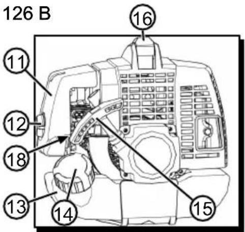
text_image
126 B ⑪ ⑫ ⑫ ⑱ ⑬ ⑬ ⑬ ⑬ ⑭ ⑭ ⑮ ⑮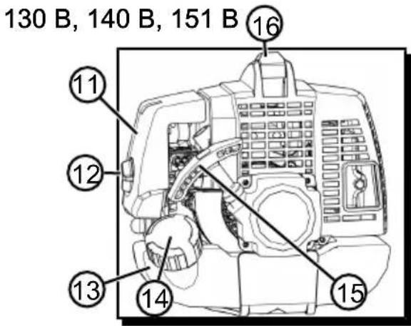
text_image
130 B, 140 B, 151 B 16 11 12 13 14 15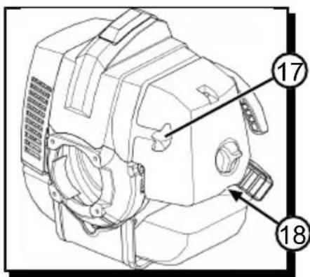
text_image
Technical diagram of a mechanical device with numbered annotations pointing to components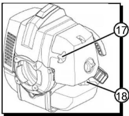
text_image
Technical diagram of a mechanical device with numbered annotations pointing to specific parts.02

text_image
126 B, 130 B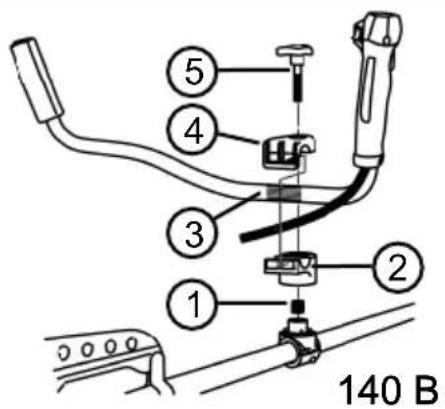
text_image
140 B03
text_image
A < B !04

text_image
2 7 3 6 ① ④ ⑤ ⑧05

text_image
Technical diagram of a mechanical device with numbered parts for identification06
126 B, 126 L, 130 B, 130L, 140 B, 140 L, 151 B

text_image
a b c d e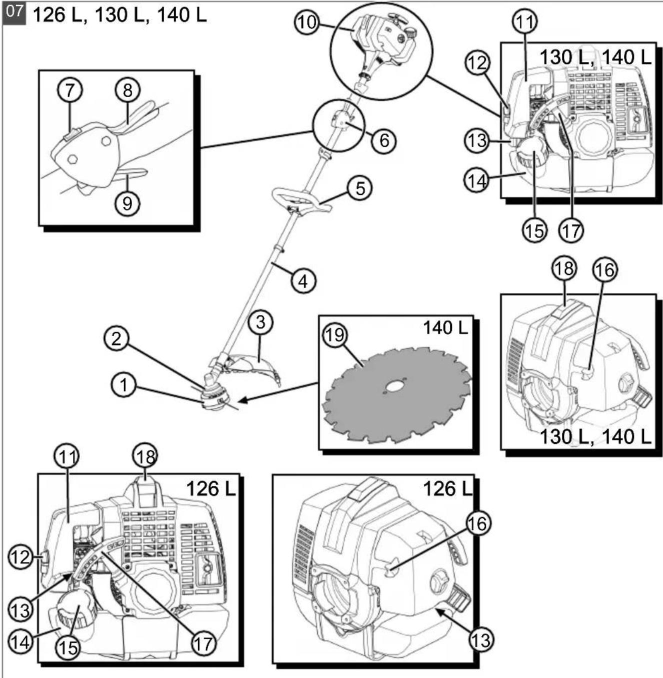
text_image
08 ③ ① ② ④ ⑤ ⑥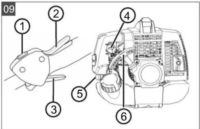
text_image
09 ① ② ③ ④ ⑤ ⑥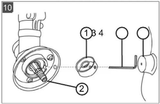
text_image
10 1 3 4 2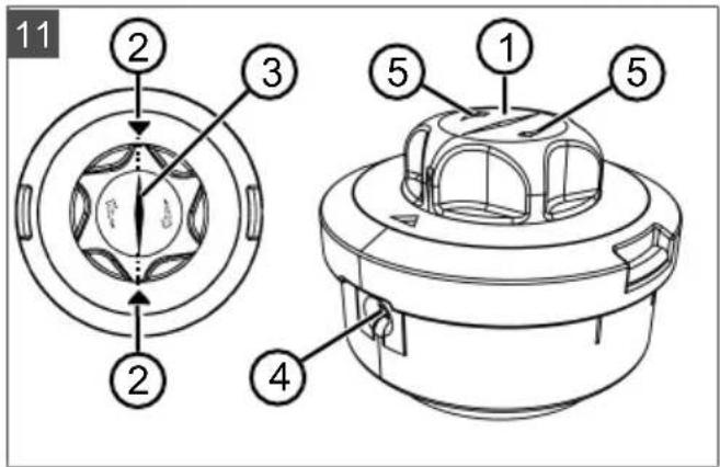
text_image
11 2 3 4 5 1 5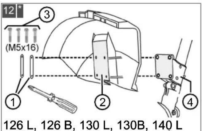
text_image
12 (M5x16) ① ② ③ ④ 126 L, 126 B, 130 L, 130B, 140 L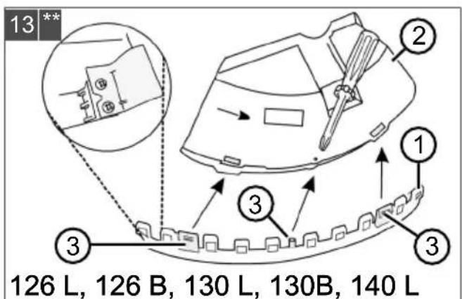
text_image
13** ② ① ③ ③ 126 L, 126 B, 130 L, 130B, 140 L**: Only for spool head
*: For spool head and 3-toothed blade
text_image
14 *** 140 L, 140 B, 151 B ② a ①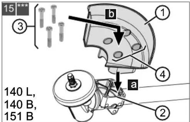
text_image
15 *** 3 b 1 4 a 2 140 L, 140 B, 151 B***: For metal circular saw blade
***: For metal circular saw blade
text_image
16 ① ② ③ ④ ⑤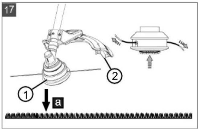
text_image
17 ① a ②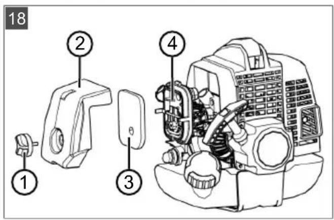
text_image
18 ① ② ③ ④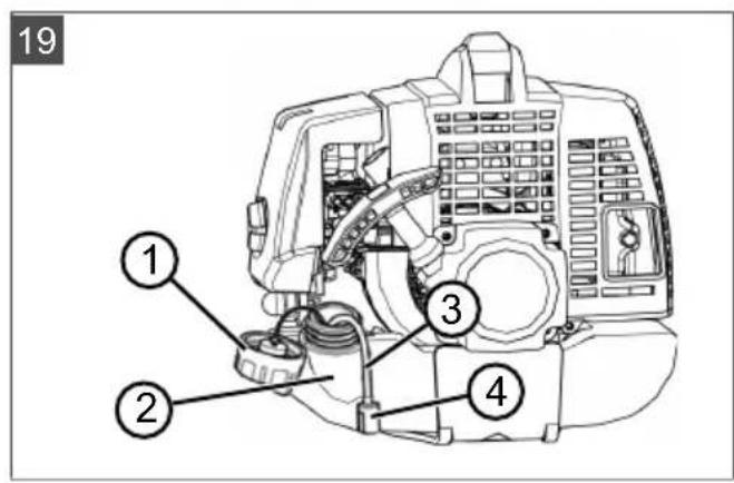
text_image
19 ① ② ③ ④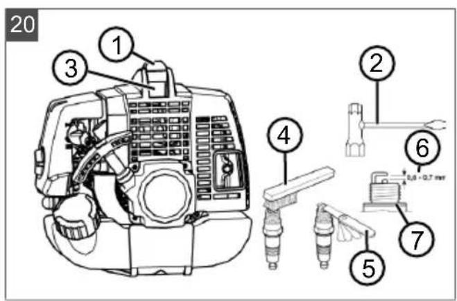
text_image
20 ① ③ ④ ② ⑥ ⑦ ⑤ L8 - Q7 min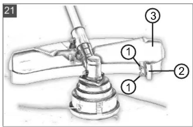
text_image
21 ① ② ③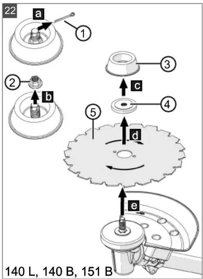
text_image
22 a 1 ② b ⑤ c ④ d e 140 L, 140 B, 151 B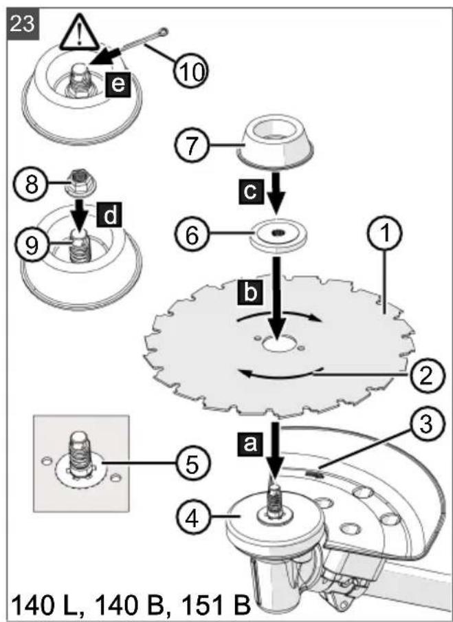
text_image
23 10 e 7 c 8 d 9 6 b 1 ① 2 a 3 5 4 140 L, 140 B, 151 B1 About these operating instructions...... 28
1.1 Symbols on the title page 28
1.2 Legends and signal words...... 28
2 Product description 28
2.1 Intended use.... 28
2.2 Possible foreseeable misuse.... 28
2.3 Residual dangers.... 28
2.4 Safety and protective devices..... 29
2.5 Symbols on the brush cutter.... 29
2.6 Scope of supply 29
2.7 Product overview (01, 07)...... 29
2.8 Approved cutting tools 30
3 Safety instructions.... 30
3.1 Operator.... 30
3.2 Personal protective equipment ..... 31
3.3 Work area safety.... 31
3.4 Appliance safety 31
3.5 Safety of persons, animals and property.... 31
3.6 Vibration load.... 32
3.7 Handling of petrol and oil.... 32
4 Assembly.... 33
4.1 Installing the "Bike" handle 126/130 B (02, 03) 33
4.2 Installing the "Bike" handle 140 B (02) 33
4.3 Installing the "Bike" handle 151 B (02, 03) 33
4.4 Installing the "Loop" handle 126/130/140 L (08) 33
4.5 Fitting the blade (04).... 33
4.6 Mounting the spool head (10)...... 34
4.7 Replacing the cutting line (11) ..... 34
4.8 Installing guard plate and guard bar 126 L-B, 130 L-B, 140 L (12) ^ , (13) ^* . 34
4.9 Installing the metal guard plate 140 B, 151 B (14) ^ , (15) ^ ..... 34
5 Start-up.... 34
5.1 Preparing and pouring in the petrol/oil mixture (16) 34
5.2 Fitting the shoulder strap 126 B/126 L/130 B/130 L/140 B/140 L/151 B (06).... 35
6 Operation.... 35
6.1 Information on engine operation ..... 35
6.2 Starting/stopping the engine (05, 09). 35
6.3 Prolonging the cutting line during operation (17).... 36
7 Working behaviour and working technique.... 36
7.1 Trimming 36
7.2 Mowing.... 36
8 Maintenance and care 37
8.1 Cleaning/replacing the air filter (18) ... 37
8.2 Checking/replacing the fuel filter (19). 37
8.3 Servicing the spark plug (20) 38
8.4 Sharpening line cutter (21)...... 38
8.5 Replacing the metal circular saw blade 140 L, 140 B, 151 B (22, 23) .... 38
8.6 Maintenance schedule 39
9 Help in case of malfunctions.... 40
10 Transport 41
11 Storage.... 41
12 Disposal.... 41
13 Technical data 42
14 Using of cutting tools and guard plates .... 43
15 Additional information for CO2 values..... 44
16 After-Sales/Service.... 44
17 Information on the Declaration of Confor- mity 44
18 Guarantee.... 44
1 ABOUT THESE OPERATING INSTRUCTIONS
The German version is the original operating instructions. All additional language versions are translations of the original operating instructions.
- Keep these operating instructions in a safe place at all times so that they can be consulted if you need any information about the appliance.
■ Only pass on the appliance to other persons together with these operating instructions.
■ Comply with the safety and warning information in these operating instructions.
1.1 Symbols on the title page
Symbol Meaning

It is essential to read through these operating instructions carefully before start-up. This is essential for safe working and trouble-free handling.

Operating instructions

Never operate the petrol powered device in the vicinity of open flames or heat sources.
1.2 Legends and signal words
⚠️ DANGER! Denotes an imminently dangerous situation which will result in fatal or serious injury if not avoided.
WARNING! Denotes a potentially dangerous situation which can result in fatal or serious injury if not avoided.
CAUTION! Denotes a potentially dangerous situation which can result in minor or moderate injury if not avoided.
IMPORTANT! Denotes a situation which can result in material damage if not avoided.
NOTE Special instructions for ease of understanding and handling.
2 PRODUCT DESCRIPTION
2.1 Intended use
126 L, 126 B, 130 L, 130 B, 140 L
The brushcutter is intended for cutting soft grass and similar vegetation. The brushcutter must be guided parallel to the ground.
140 L, 140 B, 151 B with metal circular saw blade
The circular saw blade can be used for clearing bushes, shrubs, hedges and trees with thin trunks.
Handle variants
The brushcutter is available in two versions; observe the instruction steps appropriate to your brushcutter:
■ 126 B, 130 B, 140 B, 151 B: Brushcutter with "Bike" handle
■ 126 L, 130 L, 140 L: Brushcutter with "Loop" handle
Work with the appliance only when it is fully assembled.
This appliance is intended solely for use in non-commercial applications. Any other use as well as unauthorised conversions or modifications are regarded as contrary to the intended use and will result in voiding of the warranty as well as loss of conformity; the manufacturer will thus decline any responsibility for damage and/or injury suffered by the user or third parties.
2.2 Possible foreseeable misuse
- Do not lift the appliance off the ground during operation.
■ Use the appliance only with the OEM cutting tools.
2.3 Residual dangers
Even during correct use of the appliance, there is always a certain residual risk that cannot be excluded. Depending on the use, the following potential risks can be derived from the type and construction of the appliance:
■ Throwing out of cuttings, soil and small stones
■ Throwing out of cut-off parts of the cutting line
■ Inhalation of cuttings particles if no breathing protection is worn.
■ Damage to the hearing if no hearing protection is worn.
■ Cutting injuries when reaching into the rotating cutting line or the rotating blade
2.4 Safety and protective devices
WARNING! Risk of injury. Defective and disabled safety and protective devices can result in serious injury.
■ Have any defective safety and protective devices repaired.
■ Never disable safety and protective devices.
Emergency stop
In an emergency, switch off the engine with the on/off switch.
Guard plate
The guard plate protects the operator from contact with the rotating cutting line and objects that are thrown out.
Loop handle with spacer
The "loop" handle ensures that the operator's feet do not get into the vicinity of the rotating cutting line.
2.5 Symbols on the brush cutter
Symbol Meaning
 | Pay special attention when handling this appliance! |
 | Read the operating instructions before starting operation! |
 | Wear a helmet, ear defenders and eye protection! |
 | Wear sturdy footwear! |
 | Wear protective gloves! |
 | Risk of objects being thrown out! |
Symbol Meaning
 | The distance between the appliance and persons not involved in the work must be at least 15 m in the entire area around the user. |
 | Danger during tool run-down. |
 | * Never use the brushcutter with a metal circular saw blade! |
 | Hot surface. Do not touch! |
 | Risk of fires! Pay special attention when handling petrol! |
*: For 126 L, 126 B, 130 L, 130 B only
2.6 Scope of supply
The items listed here are included in the standard scope of supply. Check that all items are present:
Brushcutter
Allen key
- Spark plug spanner
Cotter pin (04/8)
Allen screws
■ 3-toothed blade
■ Fast and Easy spool head, including spool
Fuel mixing bottle
- Carrying strap
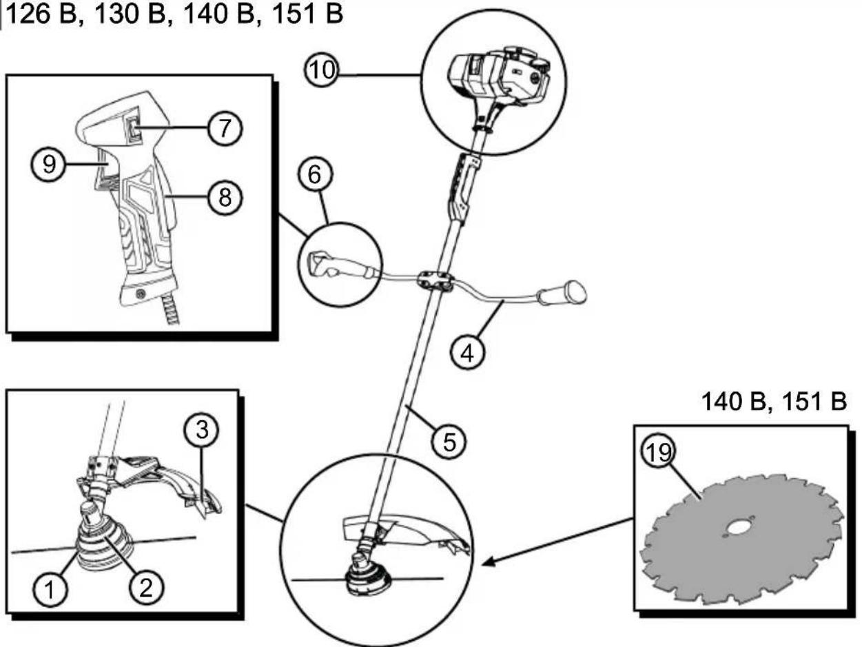
2.7 Product overview (01, 07)
126 B, 130 B, 140 B, 151 B (01)
No. Component
| 1 Spool head |
| 2 Angle-drive gearbox |
| 3 Guard plate with line cutter |
| 4 "Bike" handle |
| 5 Shaft |
| 6 Combination handle with: |
No. Component
| 7 | ■ ON/OFF switch for engine (START/ STOP) |
| 8 | ■ Locking button |
| 9 | ■ Throttle lever |
| 10 Engine block with: | |
| 11 | ■ Air filter housing |
| 12 | ■ Air filter screw |
| 13 | ■ Fuel tank |
| 14 | ■ Fuel tank cap |
| 15 | ■ Starter handle |
| 16 | ■ Spark plug cover |
| 17 | ■ Choke lever |
| 18 | ■ Primer button |
| 19 Metal circular saw blade* with metal guard plate* | |
*: For 140 B and 151 B only. Not included in the scope of supply, but can be purchased separately. See Technical Data.
126 L, 130 L, 140 L (07)
| No. | Component |
| 1 | Spool head |
| 2 | Angle-drive gearbox |
| 3 | Guard plate with line cutter |
| 4 | Shaft |
| 5 | "Loop" handle |
| 6 | Combination handle with: |
| 7 | ■ ON/OFF switch for engine (START/ STOP) |
| 8 | ■ Locking button |
| 9 | ■ Throttle lever |
| 10 | Engine block with: |
| 11 | ■ Air filter housing |
| 12 | ■ Air filter screw |
| 13 | ■ Primer button |
| 14 | ■ Fuel tank |
| 15 | ■ Fuel tank cap |
No. Component
| 16 | ■ Choke lever |
| 17 | ■ Starter handle |
| 18 | ■ Spark plug cover |
| 19 | Metal circular saw blade* with metal guard plate* |
*: For 140 L only. Not included in the scope of supply, but can be purchased separately. See Technical Data.
2.8 Approved cutting tools
Only the OEM cutting tools listed here may be used:
■ Fast and Easy Semiprofi spool head 115 mm: Article No. 127619
■ Fast and Easy Profi spool head 130 mm: Article No. 127620
■ 3-toothed blade: Article No. 112906
For 140 L, 140 B and 151 B only: Metal circular saw blade (Article No. 127812) with metal guard plate (Article No. 127831)
DANGER! Danger from cutting tools!
Non-approved cutting tools (e.g. multi-part metallic cutting tools with revolving chains and blades) and damaged cutting tools (e.g. cracks, spalling) can result in very serious injuries or even death.
■ Use only the approved OEM cutting tools.
- Replace damaged cutting tools immediately.
The use of cutting tools not approved by the manufacturer is contrary to the intended use!
3 SAFETY INSTRUCTIONS
CAUTION! Danger of hearing damage.
The appliance is extremely loud during operation. This can cause hearing damage to the operator and to persons and animals in the vicinity.
■ Only work when wearing hearing protection.
- Maintain a safe distance to persons or animals, or switch off the appliance if persons or animals approach.
NOTE It is essential to familiarise yourself with the operation of the appliance. In particular, learn how the appliance can be immediately stopped.
3.1 Operator
■ Young people under 16 years of age and people who do not know the operating in-
structions are not allowed to use the tool. Heed any country-specific safety regulations concerning the minimum age of the user.
If you are working with such an appliance for the first time: Have the salesperson or another expert explain the operation of the appliance. Or attend a course.
To operate the appliance, you must be rested and in good physical and mental health. If you must not exert yourself for health reasons, ask your doctor whether it is possible to work with this appliance.
■ Do not operate the appliance if you are under the influence of alcohol, drugs or medication.
3.2 Personal protective equipment
■ Wear clothing and protective equipment in accordance with the regulations in order to avoid injuries to the head and limbs, as well as to avoid hearing impairment.
■ The clothing must be appropriate (tightly fitting) and must not restrict movements.
■ The personal protective equipment comprises:
■ Hearing protection (e.g. ear defenders, especially when working for than 2.5 hours a day)
- Protective glasses
■ Sturdy working gloves, vibration and shock absorbent
Safety boots with high-grip sole and steel toe caps
3.3 Work area safety
■ Only operate the appliance out of doors and never in enclosed spaces.
■ Only work during daylight or under very bright artificial light.
Before working, Remove any dangerous products and objects from the working area, e.g. branches, broken glass, sharp-edged objects, pieces of metal, stones, before starting work.
■ Make sure you are standing safely. Avoid wet, slippery ground.
■ When working, move cautiously and slowly. Do not run. Watch out for obstacles.
3.4 Appliance safety
■ Only use the appliance under the following conditions:
The appliance is not dirty, especially not with petrol and oil.
The appliance show no signs of damage, especially the protective grille.
■ All controls function properly.
All accessory parts intended for the respective operating mode are fitted on the appliance.
- Do not force the power tool. It is intended for light work in the private sector. Overload can lead to damage to the appliance.
■ Never block the vacuum and ventilation grille during operation in order to avoid any overheating of the engine.
Immediately switch off the appliance if the engine begins to vibrate abnormally or strongly. There is an appliance fault in this case.
■ Never operate the appliance with worn or defective parts. Always replace defective parts with original spare parts from the manufacturer. If the appliance is operated with worn or defective parts, guarantee claims against the manufacturer are excluded.
3.5 Safety of persons, animals and property
■ Use the appliance only for the purposes for which it is intended. Any non-intended use can lead to injury and property damage.
■ Switch on the appliance only when there are no persons or animals in the working area.
- Maintain a safe distance to persons or animals, or switch off the appliance if persons or animals approach.
■ Never direct the exhaust gas jet of the engine towards persons and animals or towards inflammable products and objects.
- Do not reach into the vacuum and vent grilles when the engine is running. Injuries can occur due to rotating appliance parts.
■ Always switch off the appliance when not in use, e.g. when changing the work area, during service and maintenance, and when filling with the petrol/oil mixture.
- Immediately switch off the appliance if there is an accident in order to avoid further injuries and/or property damage.
■ Never operate the appliance with worn or defective parts. Worn or defective appliance parts can cause serious injuries.
- Keep the appliance out of the reach of children.
3.6 Vibration load
■ Danger due to vibration
The actual vibrations emitted during the use of the appliance may deviate from those stated by the manufacturer. Observe the following influencing factors before or during use:
Is the appliance being used as intended?
Is the material being cut or processed in the proper manner?
Is the appliance in a proper condition of use?
Is the cutting tool properly sharpened or is the correct cutting tool installed?
Are the handle grips and any optional vibration grips mounted, and are they firmly attached to the appliance?
■ Only operate the tool at the combustion engine speed required for the respective work. Avoid using the maximum speed in order to reduce noise and vibrations.
The noise and vibrations of the tool may increase due to improper use and maintenance. This leads to health damage. In this case, immediately switch off the tool and have it repaired by an authorised service workshop.
The degree of stress due to vibration depends on the work to be performed or on the use of the tool. Estimate the stress and plan appropriate work breaks. This considerably reduces stress due to vibration over the entire working time.
■ Extensive use of the tool exposes the operator to vibrations, which can lead to circulatory issues ("white fingers"). To avoid this risk, wear gloves and keep your hands warm. If any symptoms of "white fingers" occur, immediately consult a physician. These symptoms include: Numbness, loss of feeling, tingling, itching, pain, reduced muscular strength, changes in the colour or condition of the skin. Normally these conditions affect the fingers, hands or pulse. The risk increases at low temperatures (below approx 10°C).
Take long breaks during your working day so you can recover from the noise and the vibrations. Plan your work in such a way that the
use of appliances that generate strong vibrations is spread over several days.
If you notice an unpleasant sensation or discoloration of the skin on your hands when using the tool, stop work immediately. Take sufficient work breaks. Without sufficient breaks, a hand/arm vibration syndrome can occur.
- Minimise your risk of being exposed to vibrations. Maintain the tool according to the instructions in the operating instructions.
If the tool is used frequently, contact your dealer to purchase anti-vibration accessories (e.g. handles).
■ Define how the vibration load can be limited in a work plan.
3.7 Handling of petrol and oil
Risk of explosion and fire:
An escaping petrol/air mixture can cause an explosive atmosphere. Deflagation, explosion and fire can lead to serious and even fatal injuries if fuel is not handled properly. Observe the following:
- Do not smoke when dealing with petrol.
- Only handle petrol out of doors and never in enclosed spaces.
It is essential to heed the code of conduct stated below.
■ Only transport and store petrol and oil in containers approved for that purpose. Ensure that children have no access to stored petrol and oil.
In order to avoid ground contamination (environmental protection) when filling, ensure that no petrol or oil enters the soil. Use a funnel for filling.
■ Never fill the appliance in enclosed spaces. Petrol vapours may gather at ground level, and thereby result in a deflagration or even an explosion.
- Immediately wipe any spilled petrol off the appliance and the ground. Allow textiles used to wipe off petrol to dry in a well ventilated place before disposing of them. Otherwise, sudden self-ignition may occur.
If petrol has been spilled, petrol vapours occur. For this reason, do not start the engine at the same location and move it at least 3 m away.
- Avoid skin contact with mineral oil products. Do not inhale petrol vapours. When filling, al-
ways wear protective gloves. Change and clean protective clothing regularly.
■ Ensure that your clothing does not come into contact with petrol. If petrol has got onto your clothing, change it immediately.
■ Never fill the fuel tank while the engine is running or hot.
4 ASSEMBLY
WARNING! Danger if assembly is not carried out completely! Use of an incompletely assembled device can result in serious injury.
■ Only use the device when it is fully assembled!
■ Before switching on, check that all safety and protective devices are in place and functioning correctly!
WARNING! Risk of injury due to detaching appliance parts. Appliance parts detaching during operation can lead to serious injury.
- Attach the cutting tools so that they cannot come loose during operation.
4.1 Installing the "Bike" handle 126/130 B (02, 03)
- Place rubber sleeve (02/1) over shaft.
- Use the four Allen screws (02/2) to fasten the lower bearing shell (02/3) and the handle bracket (02/4) over the rubber sleeve (02/1).
- Insert the "bike" handle (02/5) into the handle bracket (02/4).
- Use the four Allen screws (02/7) to fasten the upper bearing shell (02/6) on the handle bracket (02/4).
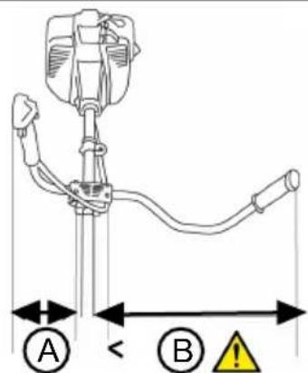
- Align the "Bike" handle in such a way that distance A is smaller than distance B (03/A, 03/B).
Note: Always guide the brushcutter to the right of your body using the "Bike" handle. Both distances are correct when the middle of the cutting head coincides with the middle of the body.
4.2 Installing the "Bike" handle 140 B (02)
- Place spring (02/1) into the bracket in the shaft.
- Place lower bearing shell (02/2) onto the spring.
- Place the marked (corrugated) section of handle bar (02/3) into lower bearing shell (02/2) of the handle bracket. Upper bearing
shell (02/4) must engage in lower bearing shell (02/2).
-
Fasten upper bearing shell (02/4) to lower bearing shell (02/2) using locking screw (02/5).
Note: The seat of the bracket can be adjusted individually on the shaft. -
Tighten locking screw (02/5).
4.3 Installing the "Bike" handle 151 B (02, 03)
- Loosen the three Allen screws of the handle bracket and remove the upper bearing shell of the handle bracket.
- Place the "Bike" handle into the lower bearing shell.
- Fasten the upper bearing shell to the lower bearing shell using the three Allen screws.
- Align the "Bike" handle in such a way that distance A is smaller than distance B (03/A, 03/B).
Note: Always guide the brushcutter to the right of your body using the "Bike" handle. Both distances are correct when the middle of the cutting head coincides with the middle of the body.
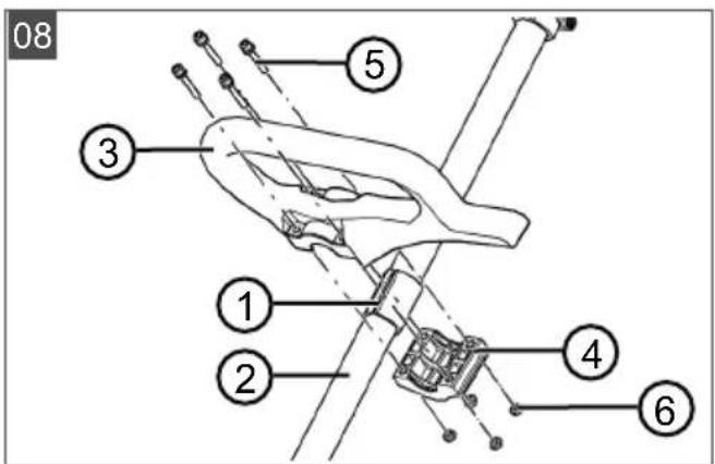
4.4 Installing the "Loop" handle 126/130/140 L (08)
- Place rubber sleeve (08/1) over shaft (08/2).
- Place "Loop" handle (08/3) from above and handle bracket (08/4) from below around the rubber sleeve.
- Insert an Allen screw (08/5) from above and screw on a nut (08/6) from below, then tighten slightly. Repeat this step with the other Allen screws and nuts.
- Tighten all Allen screws securely.
4.5 Fitting the blade (04)
WARNING! Danger of serious injury! A worn serrated washer (04/5) can allow the blade to come loose during operation and cause serious injuries.
■ Be sure to insert the cotter pin (04/8) supplied.
- Place the brushcutter so that the cutting head is pointing upwards.
-
Place driver plate (04/1) onto guide pin (04/2) of the angle-drive gearbox.
-
Place blade (04/3) onto driver plate (04/1) so that the hole in the blade lies precisely on the guide circle on the driver plate.
- Place the flange (04/4) onto the blade (04/3) so that the flat side points towards the cutting blade.
- Put on the serrated washer (04/5).
- Screw the fastening nut (04/6) onto the guide pin (04/2). To do this, insert the Allen key (04/7) into the holes provided and tighten with the spark plug spanner.
Note: Left-hand thread.
- Secure the fastening nut (04/6) with the split pin (04/8).
4.6 Mounting the spool head (10)
- Place driver plate (10/1) onto guide pin (10/2) of the angle-drive gearbox.
- To lock, insert Allen key (10/3) into hole of driver plate (10/1).
- Screw spool head (10/4) onto the angle-drive gearbox and tighten.
Note: Left-hand thread. Tighten the spool in an anti-clockwise direction.
4.7 Replacing the cutting line (11)
- Turn rotary knob (11/1) until the arrows (11/2, 11/3) are aligned.
- Push the cutting line into opening (11/4) until the line is the same length on both sides of the spool head.
- Wind cutting line into spool head: Turn rotary knob (11/1) in the direction of arrows (11/5) until the cutting line protrudes by approx. 10 cm from the spool head on both sides.
4.8 Installing guard plate and guard bar 126 L-B, 130 L-B, 140 L (12)\*, (13)\*\*
Installing the guard plate (12)\*
- Place 2 metal tabs (12/1) against guard plate (12/2).
- Fasten to handlebar (12/4) with 4 screws M5x16 (12/3).
*: For spool head and 3-toothed blade
Installing the guard bar (13)\*\*
- Push guard bar (13/1) onto guard plate (13/2). The hooks (13/3) must engage in the marked openings.
**: For spool head only
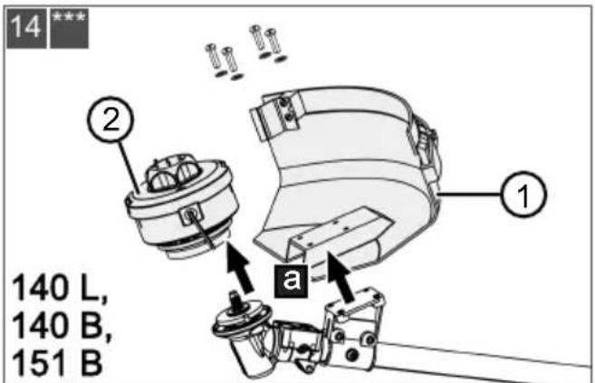
4.9 Installing the metal guard plate 140 B, 151 B (14) ^*** , (15) ^***
- Remove (14/a) the installed guard plate (14/1) and spool head (14/2) or 3-toothed blade with the guard bar.
- Place (15/a) the metal guard plate (15/1) on the gearbox (15/2).
- Screw (15/b) Allen screws (15/3) firmly into the holes (15/4).
***: For metal circular saw blade
5 START-UP
NOTE Inspect the appliance for damage every day before starting work, if it is dropped or is subjected to other impacts. Have any damage repaired before putting the appliance into operation.
5.1 Preparing and pouring in the petrol/oil mixture (16)
IMPORTANT! Danger of engine damage.
Pure petrol will result in damage and complete failure of the engine. Guarantee claims against the manufacturer are excluded in this case.
■ Always operate the engine using the specified petrol/oil mixture ratio.
Preparing the petrol/oil mixture
The 2-stroke engine requires:
■ Fresh unleaded petrol with at least 90 octane. Petrol stored for longer than 2 months will lead to deposits and malfunctions of the engine.
■ High-quality synthetic oil for 2-stroke engines Prepare a petrol/oil mixture in a ratio of 50:1 using these two constituents:
| Mixing ratio Petrol | [li-tres] | 2-stroke oil [millilitres] |
| 50 parts petrol: 1 part 2-stroke oil | 1 l 20 ml | |
| 3 l 60 ml | ||
| 5 l 100 ml |
- Pour the petrol and 2-stroke oil into a fuel mixing bottle (quantities, see table, depending on the size of the fuel mixing bottle).
- Close the fuel mixing bottle and shake vigorously several times so that the petrol and oil can mix thoroughly.
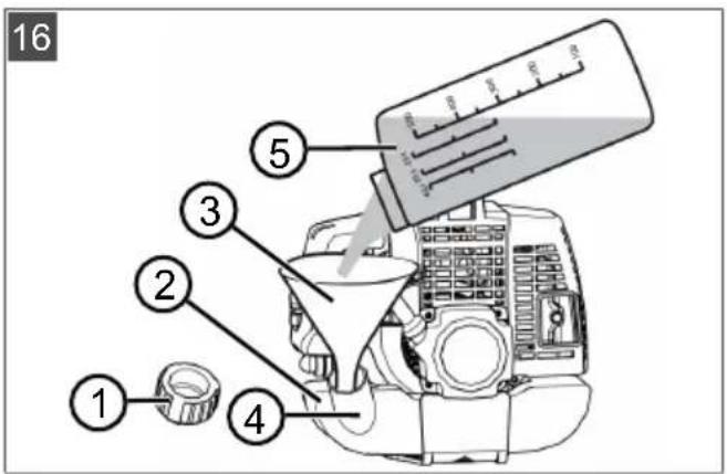
Pouring in the petrol/oil mixture (16)
-
Place the appliance on a level, horizontal surface. The cap (16/1) of the fuel tank must be facing upwards.
-
Wipe the fuel tank cap (16/1), the fuel tank (16/2) and the surrounding appliance parts clean so that no dirt can get into the fuel tank when the petrol/oil mixture is poured in.
-
Open the fuel tank cap slowly so the pressurised petrol/air mixture can slowly escape from the fuel tank into the atmosphere. Leave the cap hanging on the fuel tank.
-
Insert a funnel (16/3) into the filler neck (16/4) of the fuel tank.
-
Pour the prepared petrol/oil mixture from the fuel mixing bottle (16/5) into the fuel tank up to the lower edge of the filler neck, but not higher.
-
Remove the funnel and screw on the cap finger-tight.
-
Wipe any spilled petrol/oil mixture off the appliance and the surface.
5.2 Fitting the shoulder strap 126 B/126 L/130 B/130 L/140 B/140 L/151 B (06)
See graphic (06).
6 OPERATION
For 126 L, 126 B, 130 L, 130 B only:
DANGER! Danger from cutting tools! Use of cutting tools not approved by the manufacturer can result in severe or even fatal injuries.
■ Never operate the brushcutter with a metal circular saw blade!
6.1 Information on engine operation
Before starting
Place the brushcutter level and free of obstacles on the ground. The cutting tool must not be touching any objects or the ground.
When starting
- Do not stand on the shaft to avoid damage to the shaft and/or the angle-drive gearbox inside the shaft.
■ Make sure you are standing securely and hold the brushcutter firmly at the housing flange.
Positions of the choke lever

CHOKE RUN

Cold start (choke lever in CHOKE position)
If the engine is cold, i.e. if it has not been in use for more than 5 minutes, a "cold start" is carried out.
Warm start (choke lever in RUN position)
If the engine is still warm from use, i.e. shortly after it was switched off, a "warm start" is carried out. The choke is not used in this case.
6.2 Starting/stopping the engine (05, 09)
NOTE With the "Ready to Start" function, the ON/OFF switch is always in the ON position. Push the ON/OFF switch to the OFF position to stop the appliance. When the switch is pressed, it returns automatically to the ON position.
NOTE Automatic resetting of the choke
lever. In the event of an immediate start of the engine, the choke lever returns automatically to the RUN position when the throttle lever is pressed.
Cold start
-
Turn choke lever (05/4, 09/4) to the CHOKE position.
-
Press primer (05/5, 09/5) approx. 7 to 10 times briefly and firmly.
3. Starting the engine:
■ Press the appliance firmly onto the ground with one hand.
■ With the other hand, pull starter handle (05/6, 09/6), first carefully and slowly until resistance is felt, and then firmly and quickly upwards until resistance is felt again (approx. 1 arm length).
- Allow the starter rope to coil up again, but without releasing the starter handle.
■ Repeat the previous steps several times until the engine starts or stalls.
■ Turn choke lever (05/4, 09/4) to the RUN position.
■ Press the appliance firmly onto the ground with one hand.
■ With the other hand, pull starter handle (05/6, 09/6), first carefully and slowly until
resistance is felt, and then firmly and quickly upwards until resistance is felt again (approx. 1 arm length).
-
Allow the starter rope to coil up again, but without releasing the starter handle.
■ Repeat the previous steps several times until the engine starts and runs smoothly. -
Allow the engine to warm up for a few minutes.
Warm start
If the engine is still warm from use, i.e. shortly after it was switched off, a "warm start" is carried out. The choke is not used here.
- (Optional) Turn choke lever (05/4, 09/4) to the CHOKE position and then immediately back to the RUN position. Automatic half throttle is now set.
■ Press the appliance firmly onto the ground with one hand.
■ With the other hand, pull starter handle (05/6, 09/6), first carefully and slowly until resistance is felt, and then firmly and quickly upwards until resistance is felt again (approx. 1 arm length). - Allow the starter rope to coil up again, but without releasing the starter handle.
■ Repeat the previous steps several times until the engine starts and runs smoothly.
The engine runs at idle speed.
Note: Press the throttle lever again if the engine no longer runs smoothly.
Stopping the engine
- Release throttle lever (05/2, 09/3) and allow the engine run at idle speed.
- Move ON/OFF switch (05/1, 09/1) to the STOP position and hold it there for a few seconds.
- Wait until the cutting tool has come to a complete standstill.
6.3 Prolonging the cutting line during operation (17)
The cutting line becomes shorter and frays during operation.
- Allow the engine to run at full speed.
- Tap (17/a) the spool head (17/1) on the ground from time to time. This unwinds a piece of new cutting line from the spool and cuts off the used end of the cutting line (17/2).
7 WORKING BEHAVIOUR AND WORKING TECHNIQUE
■ Make sure you are standing securely.
■ Never work on a smooth, slippery hill or slope.
- When working on a slope, always stand below the cutting tool.
■ Always allow the engine to run in the upper speed range during trimming and mowing, as the trimmer then cuts best.
If the cutting line jams
High grass or scrub can cause the cutting line to jam.
■ Avoiding blockages: Cut long grass in several passes. Always proceed from top to bottom.
In the event of a blockage: Switch off the engine immediately and hold the appliance in the air so that the engine is not damaged.
7.1 Trimming
- Keep the appliance away from delicate plants.
Low trimming
■ Guide the cutter head with a slight forward angle so that the cutting line trims just above the ground.
■ Always trim away from your body.
Trimming at fences and foundations
■ Guide the appliance slowly and carefully so that the cutting line does not come into contact with solid obstacles.
i NOTE Trimming around brick walls, foundations, fences and trees results in increased cutting line wear.
Trimming around tree trunks
■ Guide the appliance slowly and carefully around tree trunks so that the cutting line does not touch the tree bark.
- Trim from left to right around tree trunks.
- Cut grass and weeds with the tip of the cutting line and hold the cutter head with a slight forward angle.
7.2 Mowing
■ Guide the cutter head in a smooth horizontal, arc-shaped movement from one side to the other.
- Hold the cutter head parallel to the ground at all times.
■ Long grass should be mown in several passes. Always proceed from top to bottom.
■ The appliance cuts best at very high speed. Therefore, do not overload the appliance by cutting long grass.
■ Tilt the cutter head at an angle of 30^ to the right to mow with the tip of the cutting line. Walk forwards slowly.
- Do not move the appliance directly against hard obstacles (e.g. walls), but mow sideways. This protects the cutting line.
8 MAINTENANCE AND CARE
⚠️ DANGER! Risk of injury or death due to improper maintenance. Maintenance work carried out by unqualified persons and the use of non-approved spare parts, as well as removing or modifying safety devices can result in serious injuries and even death during operation of the appliance.
- Do not remove or deactivate any safety installations.
■ Use only approved OEM spare parts.
■ Ensure through regular and proper maintenance that the appliance is in a clean and functional condition at all times.
CAUTION! Risk of injury. Sharp-edged and moving appliance parts can lead to injury.
■ Always wear protective gloves during maintenance, care and cleaning work!
Proper maintenance and care is necessary to ensure the functionality and safety of the brushcutter. Note the following points:
- Carry out maintenance and care work only if you have the necessary knowledge and tools.
■ Wait until the engine has cooled down completely. - Replace worn or defective brushcutter parts only with OEM spare parts.
- Do not carry out any maintenance and care work that is not described in these operating instructions. Have an authorise service workshop to do this work. Any infringements will invalidate the manufacturer's warranty.
The intervals for the maintenance and care work described here can be found in the maintenance schedule.
Use only the approved cutting tools!
8.1 Cleaning/replacing the air filter (18)
IMPORTANT! Danger of engine damage. Operation of the engine without air filter will result in serious engine damage!
■ Never operate the appliance without air filter.
■ Clean the air filter at regular intervals.
■ Replace a damaged air filter.
- Remove the air filter:
■ Loosen the air filter screw (18/1) until the air filter housing cover (18/2) is loose.
■ Pull off the air filter housing cover.
■ Pull the filter sponge (18/3) from the frame (18/4).
- Cleaning the filter sponge (18/3):
■ Squeeze out the filter sponge, then wash out with soap and water. Do not use petrol or other solvents!
- Allow the filter sponge to dry thoroughly until it contains no more water. A wet filter can make the engine difficult to start.
- Clean the air filter housing thoroughly using a cloth.
- Replacing the filter sponge (18/3):
- Replace the filter sponge if it is no longer elastic or falls apart.
- Install the air filter:
■ Push the filter sponge (18/3) onto the frame (18/4).
■ Push on the air filter housing cover (18/2) and hold in place.
■ Screw in the air filter screw (18/1) until the air filter housing cover is tight.
8.2 Checking/replacing the fuel filter (19)
The felt-like fuel filter is mounted on the intake head in the fuel tank. If the fuel filter becomes hard, dirty or clogged, less petrol flows to the engine. In this case the fuel filter must be replaced.
We recommend that this work is carried out by an authorised service workshop.
- Preparing the appliance:
■ To empty the fuel tank: Allow the engine to run until it stops itself.
Place the appliance on a level, horizontal surface. The cap (19/1) of the fuel tank (19/2) must be facing upwards.
■ Wipe the fuel tank cap, the fuel tank and the surrounding appliance parts clean so that no dirt can get into the fuel tank.
- Checking/replacing the fuel filter:
■ Unscrew the cap (19/1) of the fuel tank (19/2). Leave the cap hanging on the fuel tank.
■ Use a wire hook to pull the intake head (19/3) out of the fuel tank.
- Inspect the fuel filter (19/4). If the felt has become hard, dirty or clogged: Pull off the fuel filter and push a new fuel filter onto the intake head.
- Push the intake head into the fuel tank again.
- Mix and pour in the petrol/oil mixture (see chapter 5.1 "Preparing and pouring in the petrol/oil mixture (16)", page 34).
8.3 Servicing the spark plug (20)
- Removing the spark plug:
■ Remove spark plug connector (20/1).
■ Unscrew spark plug (20/3) using a spark plug spanner (20/2).
- Inspecting the spark plug:
If the spark plug is pale brown: The engine is working correctly and the spark plug is in order. If necessary: Carefully brush the spark plug clean using a fine wire brush (20/4).
If the spark plug is sooty, oily, encrusted, melted or the contacts bridged: The spark plug is defective. Replace the spark plug with a new spark plug. Use the specified spark plug type (see chapter 13 "Technical data", page 42).
If, after a short period of operation, the spark plug is defective again, the engine and the carburettor settings must be checked by an authorised service workshop.
- Checking the electrode gap:
Use a feeler gauge (20/5) to check that the electrode gap (20/6) is 0.6 – 0.7 mm. If not, carefully tap the electrodes closer together or carefully bend them apart.
- When the prescribed interval is reached or if the spark plug is defective:
- Replace the spark plug with a new spark plug. Use the specified spark plug type (see chapter 13 "Technical data", page 42).
- Installing the spark plug:
■ Ensure the spark plug seal ring (20/7) is on the spark plug.
- Screw in the spark plug again by hand and tighten using the spark plug spanner (torque 12 – 15 Nm).
■ Push on the spark plug connector again firmly.
8.4 Sharpening line cutter (21)
- Unfasten the mounting screws (21/1) and remove the line cutter (21/2) from the guard plate (21/3).
- Clamp the line cutter in a vice and sharpen it using a file. File in one direction only.
- Re-attach the line cutter to the guard plate using the mounting screws. Tighten the mounting screws firmly.
8.5 Replacing the metal circular saw blade 140 L, 140 B, 151 B (22, 23)
Remove the old metal circular saw blade (22)
- Set down the brushcutter so that the cutting head is facing upwards.
- Pull out (22/a) split pin (22/1).
- Unscrew (22/b) fastening nut (22/2).
- Pull off (22/c) flange (22/3).
- Pull off (22/d) serrated washer (22/4).
- Remove (22/e) the old metal circular saw blade (22/5).
Installing the new metal circular saw blade (23)
WARNING! Danger of serious injury! A worn serrated washer (23/6) can allow the cutting blade to come loose during operation and cause serious injuries.
■ Be sure to insert the cotter pin (23/10) supplied.
- Push on (23/a) new metal circular saw blade (23/1):
■ The arrows on circular saw blade (23/2) and metal guard plate (23/3) must be aligned.
Place the circular saw blade on driver plate (23/4) so that its opening aligns exactly with guide circle (23/5) of the driver plate.
-
Push on (23/b) serrated washer (23/6).
-
Place flange (23/7) onto the circular saw blade (23/c) so that the flat side is facing towards the cutting blade.
-
Screw (23/d) fastening nut (23/8) onto guide pin (23/9).
-
Insert (23/e) cotter pin (23/10) through the guide pin and bend open the ends of the cotter pin.
8.6 Maintenance schedule
The following jobs are allowed to be carried out by the user independently. All other maintenance,
service and repair work must be carried out in an authorised service workshop.
NOTE Shorter maintenance intervals than those stated in this table may be necessary in case of severe loading and high temperatures.
| Activity Once | after 5 operating hours | Before each use | Every week | Every 50 operating hours | Every 100 operating hours | as required | Before the working season | Every 5 years |
| Carburettor | ||||||||
| check idle speed X | ||||||||
| Air filter | ||||||||
| Clean X | ||||||||
| Replace X | ||||||||
| Spark plug | ||||||||
| check electrode gap, adjust if necessary | X | |||||||
| Replace X X | ||||||||
| Cooling air inlet | ||||||||
| Clean X X X | ||||||||
| Silencer | ||||||||
| Visual inspection for condition | X | |||||||
| Fuel tank | ||||||||
| Clean X X | ||||||||
| Fuel filter | ||||||||
| Replace X | ||||||||
| Control elements | ||||||||
| ON/OFF switch, locking button, throttle lever, starter rope | X | |||||||
| All accessible screws (except set screws) | ||||||||
| Retighten | X | XX | ||||||
| Complete appliance | ||||||||
| Visual inspection for condition | X | |||||||
| Clean X X X | ||||||||
9 HELP IN CASE OF MALFUNCTIONS

CAUTION! Risk of injury. Sharp-edged
and moving appliance parts can lead to injury.
■ Always wear protective gloves during maintenance, care and cleaning work!
■ Switch the appliance off.

NOTE For malfunctions that are not listed in
this table or that you cannot resolve yourself, please contact our customer service.
| Malfunction Cause Remedy | ||
| Engine does not start, or only starts with difficulty. | Engine start was not carried out properly. | see chapter 6.2 "Starting/stopping the engine (05, 09)", page 35 |
| Spark plug is dirty, defective or the electrode gap is not right. | see chapter 8.3 "Servicing the spark plug (20)", page 38 | |
| Air filter is clogged. see chapter 8.1 | "Cleaning/replacing the air filter (18)", page 37 | |
| Fuel filter is worn. see chapter 8.2 | "Checking/replacing the fuel filter (19)", page 37 | |
| Carburettor settings are not cor-rect. | Contact an authorised service work-shop. | |
| Choke lever is in CHOKE posi-tion. | Move choke lever to RUN. | |
| Engine starts, but the en-gine output is low. | Choke lever is in CHOKE posi-tion. | Move choke lever to RUN. |
| Air filter is clogged. see chapter 8.1 | "Cleaning/replacing the air filter (18)", page 37 | |
| Fuel filter is worn. see chapter 8.2 | "Checking/replacing the fuel filter (19)", page 37 | |
| Carburettor settings are not cor-rect. | Contact an authorised service work-shop. | |
| Engine not running smoothly and engine speed not increasing when the throttle is ap-plied. | Spark plug is dirty, defective or the electrode gap is not right. | see chapter 8.3 "Servicing the spark plug (20)", page 38 |
| Carburettor settings are not cor-rect. | Contact an authorised service work-shop. | |
| Engine exhaust smoking heavily, appears blue. | Amount of oil in the petrol/oil mixture is too high. | Pour in petrol/oil mixture with correct mixture ratio.see chapter 5.1 "Preparing and pouring in the petrol/oil mixture (16)", page 34 |
| Carburettor settings are not cor-rect. | Contact an authorised service work-shop. | |
| Engine starts abnormally and vibrates strongly. | Appliance/engine parts have come loose and/or are damaged. | 1. Stop the motor.2. Inspect appliance for damage.3. Inspect the spark plug, see chapter 8.3 "Servicing the spark plug (17)", page 384. Contact an authorised service workshop. |
10 TRANSPORT
Transporting the appliance between two working areas
- Switch off the engine.
- Put the transport protection onto the blade.
- Hold the brushcutter firmly at the engine block and the handle.
- Walk carefully to the next working area. Take care not to endanger persons or animals.
Transporting the appliance in a vehicle
- If possible: Empty the fuel tank by allowing the engine to run.
- Switch off the engine.
- Put the transport protection onto the blade.
- Ensure that the appliance cannot tip over while driving to prevent the petrol/oil mixture from running out:
Place the appliance on the floor of the vehicle so that the fuel tank cap is facing upwards. The fuel tank must be securely closed.
- Fix the appliance to the floor of the vehicle.
11 STORAGE
If the appliance is not going to be used for more than 2 – 3 months, the following work is necessary to avoid any damage:
-
Empty the fuel tank:
-
Allow the engine to run until it stops itself. Then there is no longer any petrol/oil mixture in the fuel tank or carburettor and deposits cannot form.
-
Cleaning the appliance:
■ Wipe the entire appliance and accessory parts with a cleaning rag. Do not use petrol or other solvents.
■ Remove any dirt from all appliance openings (including cooling openings for the engine).
-
Oiling the cylinder:
-
Allow the appliance to cool down completely.
■ Pull off the spark plug connector and unscrew the spark plug (see chapter 8.3 "Servicing the spark plug (20)", page 38) -
Drop a little oil into the spark plug opening.
■ Slowly pull on the starter handle so the piston moves and the oil is distributed in the cylinder.
■ Screw in the spark plug again tightly and push on the spark plug connector. -
Put the transport protection onto the blade.
- Store the device in a cool, dry place.
CAUTION! Risk of injury. If the appliance is accessible to children and unauthorised persons during storage, this can result in injury.
■ Store the appliance out of the reach of children and unauthorised persons.
12 DISPOSAL

Petrol and motor oil do not belong in household waste or the public sewer system, but should be collected and disposed of separately.
■ Before disposing of the device you must empty the fuel tank and the engine oil tank!
Packaging, equipment and accessories are made from recyclable materials, and must be disposed of accordingly.
13 TECHNICAL DATA
| 126 B 126 L 130 B 130 L 140 B 140 L 151 B | |||||||
| Article numbers: | |||||||
| Brushcutter 127610 | 127611 127612 127613 127829 127845 127830 | ||||||
| Metal circular saw blade* | o o o o 127812 127812 127812 | ||||||
| Metal guard plate* o o o o 127831 127831 127831 | |||||||
| Technical data: | |||||||
| Dry weight | 5.2 kg 4.9 kg 6.0 kg 5.5 kg 7.7 kg 7.2 kg 8.6 kg | ||||||
| Engine type | Air-cooled 2-stroke engine, 1 cylinder | Air-cooled 2-stroke engine, 1 cylinder | Air-cooled 2-stroke engine, 1 cylinder | Air-cooled 2-stroke engine, 1 cylinder | Air-cooled 2-stroke engine, 1 cylinder | Air-cooled 2-stroke engine, 1 cylinder | Air-cooled 2-stroke engine, 1 cylinder |
| Displacement, cubic capacity | 25.4 cm^3 | 25.4 cm^3 | 29.5 cm^3 | 29.5 cm^3 | 40.2 cm^3 | 40.2 cm^3 | 50.8 cm^3 |
| Maximum engine power | 0.8 kW / 8000 rpm | 0.8 kW / 8000 rpm | 0.9 kW / 9500 rpm | 0.9 kW / 9500 rpm | 1.5 kW / 8500 rpm | 1.5 kW / 8500 rpm | 1.9 kW / 8500 rpm |
| Maximum speed | 12000 rpm | 12000 rpm 12000 rpm 12000 rpm 11000 rpm 11000 rpm 11000 rpm | |||||
| Idle speed | 3200(±200) rpm | 3200(±200) rpm | 3200(±200) rpm | 3200(±200) rpm | 2800(±280) rpm | 2800(±280) rpm | 2800(±280) rpm |
| Spark plug | L8RTC/BP-MR7A/BP-MR6A/RCJ6Y | L8RTC/BP-MR7A/BP-MR6A/RCJ6Y | L8RTC/BP-MR7A/BP-MR6A/RCJ6Y | L8RTC/BP-MR7A/BP-MR6A/RCJ6Y | L8RTC/BP-MR7A/BP-MR6A/RCJ6Y | L8RTC/BP-MR7A/BP-MR6B/RCJ6Y | L8RTC/BP-MR7A/BP-MR6A/RCJ6Y |
| Ignition | electronic electronic electronic electronic electronic electronic electronic electronic electronic electronic electronic electronic electronic electronic electronic electronic electronic electronic electronic electronic electronic electronic electronic electronic electronic electronic electronic electronic electronic electronic electronic electronic electronic electronic electronic electronic electronic electronic electronic electronic electronic electronic electronic electronic electronic electronic electronic electronic electronic electronic electronic electronic electronic electronic electronic electronic electronic electronic electronic electronic electronic electronic electronic electronic electronic electronic electronic electronic electronic electronic electronic electronic electronic electronic electronic electronic electronic electronic electronic electronic electronic electronic electronic electronic electronic electronic electronic electronic electronic electronic electronic electronic electronic electronic electronic electronic electronic electronic electronic electronic electronic electronics | ||||||
| Clutch | Centrifugal clutch | Centrifugal clutch | Centrifugal clutch | Centrifugal clutch | Centrifugal clutch | Centrifugal clutch | Centrifugal clutch |
| Tank volume (petrol) | 0,65 | 0,65 | 0,65 | 0,65 | 0,78 | 0,78 | 0,78 | | ||||||
| Petrol | lead-free, minimum 90 octane | lead-free, minimum 90 octane | lead-free, minimum 90 octane | lead-free, minimum 90 octane | lead-free, minimum 90 octane | lead-free, minimum 90 octane | lead-free, minimum 90 octane |
| Oil | synthetic, for 2-stroke engines | synthetic, for 2-stroke engines | synthetic, for 2-stroke engines | synthetic, for 2-stroke engines | synthetic, for 2-stroke engines | synthetic, for 2-stroke engines | synthetic, for 2-stroke engines |
| Fuel mixture ratio [petrol:2-stroke oil] | 50:1 50:1 | 50:1 50:1 50:1 | 50:1 50:1 | ||||
| Hand grip | "Bike" handle | "Loop" handle | "Bike" handle | "Loop" handle | "Bike" handle | "Loop" handle | "Bike" handle |
| Cutting width of the spool (diameter) | 415 mm 415 mm 415 mm 415 mm 415 mm 415 mm 415 mm | ||||||
| Diameter of the cutting line | 2.5 mm 2.5 mm 2.5 mm 2.5 mm 2.5 mm 2.5 mm | ||||||
| Diameter of the blade | 255 mm 255 mm 255 mm 255 mm 255 mm 255 mm | ||||||
| Diameter of the metal circular saw blade* | - - - - 200 mm 200 mm 200 mm | ||||||
| Speed of the tool | max. 9000(±500) rpm | max. 9000(±500) rpm | max. 9000(±500) rpm | max. 9000(±500) rpm | max. 8000(±500) rpm | max. 8000(±500) rpm | max. 8000(±500) rpm |
| Sound pressure level LpA (EN ISO 22868) | |||||||
| Blades | 92.9 dB(A) | 92.9 dB(A) 96.6 | dB(A) 96.6 dB(A) 94.3 dB(A) | 94.3 dB(A) 95.8 dB(A) | |||
| Spool head | 92.6 dB(A) | 92.6 dB(A) 93.5 | dB(A) 93.5 dB(A) 98.0 dB(A) | 98.0 dB(A) 97.6 dB(A) | |||
| Measurement uncertainty | K = 3,0dB(A) | K = 3,0dB(A) | K = 3,0dB(A) | K = 3,0dB(A) | K = 3,0dB(A) | K = 3,0dB(A) | K = 3,0dB(A) |
| Measured sound power L_W A (EN ISO 22868) | |||||||
| Blades | 107.1 dB(A) | 107.1 dB(A) 107.8 dB(A) 107.8 | dB(A) 109.1 | dB(A) 109.1 dB(A) 111.7 dB(A) | |||
| Spool head | 106.5 dB(A) | 106.5 dB(A) 108.0 dB(A) 108.0 | dB(A) 111.8 | dB(A) 111.8 dB(A) 113.9 dB(A) | |||
| Measurement uncertainty | K = 3,0dB(A) | K = 3,0dB(A) | K = 3,0dB(A) | K = 3,0dB(A) | K = 3,0dB(A) | K = 3,0dB(A) | K = 3,0dB(A) |
| Guaranteed sound power | 108.0 dB(A) | 108.0 dB(A) 109.0 dB(A) 109.0 | dB(A) 113.0 | dB(A) 113.0 dB(A) 115.0 dB(A) | |||
| Measured vibration level at handle (EN ISO 22867) | |||||||
| Blades | 9.1 m/s ^2 | 10.3 m/s ^2 | 4.42 m/s ^2 | 6.69 m/s ^2 | 5.8 m/s ^2 | 10.28 m/s ^2 | 7.82 m/s ^2 |
| Spool head | 6.21 m/s ^2 | 8.34 m/s ^2 | 4.66 m/s ^2 | 5.0 m/s ^2 | 4.44 m/s ^2 | 7.96 m/s ^2 | 7.1 m/s ^2 |
| Measurement uncertainty | K = 1.5 m/s ^2 | K = 1.5 m/s ^2 | K = 1.5 m/s ^2 | K = 1.5 m/s ^2 | K = 1.5 m/s ^2 | K = 1.5 m/s ^2 | K = 1.5 m/s ^2 |
| *: Not included in the scope of supply, but can be purchased separately. o: Technically not possible. | |||||||
14 USING OF CUTTING TOOLS AND GUARD PLATES
| 126 B 126 L 130 B 130 L 140 B 140 L 151 B | ||||||
| Spool head with guard plate and guard bar | x x x x x x x | |||||
| 3-toothed blade with guard plate | x x x x x x x | |||||
| ■ Guard bar - - - - - - | ||||||
| Metal circular saw blade with metal guard plate | o o o o x x x | |||||
| x: can be used, -: must be removed, o: technically not possible | ||||||
15 ADDITIONAL INFORMATION FOR CO2 VALUES
According to Article 43 (4) of Directive (EU) 2016/1628, we are obliged to provide the CO _2 value determined during the course of the EU type approval procedure.
The CO_2 values of the Honda engines with EU type approval can be found at https://www.al-ko.com/shop/media/al-ko-engines/co2.pdf.
This CO_2 measurement is the result of testing of a (master) engine representative of the engine type or engine family in a fixed test cycle under laboratory conditions and does not constitute an express or implied warranty of the performance of a particular engine.
16 AFTER-SALES/SERVICE
In the event of questions of warranty, repair or spare parts, please contact your nearest AL-KO Service Centre. These can be found on the Internet at: www.alko-garden.com/service-contacts
Further information on spare parts can be found at: www.alko-garden.com/spareparts
17 INFORMATION ON THE DECLARATION OF CONFORMITY
We hereby declare, as the exclusively responsible party, that this product in its marketed form meets the requirements of the harmonised EU Directives, EU safety standards and the product-specific standards. The Declaration of Conformity forms part of the operating instructions and is included with the machine.
18 GUARANTEE
We will resolve any material or manufacturing faults on the appliance during the legal warranty period for claims relating to faults, in accordance with our choice either to repair or replace. The legal warranty period is determined by the legislation of the country in which the appliance was purchased.
Our warranty promise applies only if:
■ These operating instructions are heeded
■ The appliance is handled correctly
■ Original spare parts have been used
The warranty becomes void in the case of:
■ Unauthorised repair attempts
■ Unauthorised technical modifications
Non-intended use
The guarantee excludes:
■ Paint damage that can be attributed to normal wear and tear
■ Wear parts that are marked with a frame xxxxxx (x) on the spare parts card
■ Internal combustion engines (these are covered by the guarantee provisions of the corresponding engine manufacturers)
The guarantee period commences with purchase by the first end user. The date on the proof of purchase is decisive. In the event of a guarantee claim, please take this guarantee declaration and the original proof of purchase, and contact your dealer or the nearest authorised customer service centre. This statement does not affect the purchaser's statutory claims for defects against the vendor.
VERTALING VAN DE ORIGINELE GEBRUIKERSHANDLEIDING
Inhoudsopgave
2 PRODUCTOMSCHRIJVING
2.1 Beoogd gebruik
126 L, 126 B, 130 L, 130 B, 140 L
10 Transport ....139
11 Shranjevanje....139
12 Odstranjevanje ....139
7 ARBEIDSFREMTREDEN OG ARBEIDSTEKNIKK
8 VEDLIKEHOLD OG PLEIE
4.6 Trimmipea monteerimine (10)
Imported by: AL-KO Gardentech UK Ltd, Murray way, Wincanton, Somerset, BA9 9RS / UK | +44 (0) 1963 828055 shop.uk@al-ko.com | www.alko-garden.uk