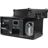
Instant Air 2000 Pro - Effect machine Cameo - Free user manual and instructions
Find the device manual for free Instant Air 2000 Pro Cameo in PDF.

| Product type | Professional wind machine |
| Brand | Cameo |
| Model | Instant Air 2000 Pro |
| Reference | CLIA2000PRO |
| Maximum air flow | 56 m³/min |
| Air velocity | 12 m/s |
| Fan rotation speed | 440-2500 rpm |
| Fan diameter | 310 mm |
| DMX inputs | XLR male 3-pin and 5-pin |
| DMX outputs | XLR female 3-pin and 5-pin |
| DMX mode | 1 channel |
| Control | DMX512, manual, radio remote control (433 MHz) |
| Control elements | START/STOP (MODE), UP, DOWN (illuminated) |
| Display | 3-character LED display |
| Operating voltage | 230 V AC / 50 Hz |
| Power consumption | 250 W |
| Fuse | T3.15 AL / 250 V (5 x 20 mm) |
| Operating ambient temperature | 0 °C to 40 °C |
| Relative humidity | < 85 %, non-condensing |
| Housing material | Metal, black color |
| Dimensions (diameter × height with stand) | 385 × 515 mm |
| Weight | 8.6 kg |
| Included accessories | Power cord CEE 7/7, radio remote control |
| Additional features | Carrying handle, adjustable stand, vertical orientation via thumbscrews |
| Minimum distance to flammable materials | 0.5 m |
| Cooling time before handling | 10 minutes |
Frequently Asked Questions - Instant Air 2000 Pro Cameo
User questions about Instant Air 2000 Pro Cameo
0 question about this device. Answer the ones you know or ask your own.
Ask a new question about this device
Download the instructions for your Effect machine in PDF format for free! Find your manual Instant Air 2000 Pro - Cameo and take your electronic device back in hand. On this page are published all the documents necessary for the use of your device. Instant Air 2000 Pro by Cameo.
USER MANUAL Instant Air 2000 Pro Cameo
WIND MACHINE WITH ADJUSTABLE FAN SPEED
AND AIR FLOW DIRECTION
CLIA2000PRO
CONTENTS / INHALTSVERZEICHNIS / CONTENU / CONTENIDO / TREŚĆ / CONTENUTO
ENGLISH
PREVENTIVE MEASURES 3
INTRODUCTION 4
CONNECTIONS, CONTROL AND DISPLAY ELEMENTS 5
OPERATION 6
SETUP 7
DMX TECHNOLOGY 7
TECHNICAL SPECIFICATIONS 8
MANUFACTURER'S DECLARATIONS 9
DMX CONTROL 45
DEUTSCH
We have designed this product to operate reliably over many years. Please read this User's Manual carefully, so that you can begin making optimum use of your Cameo Light product quickly. Learn more about Cameo Light on our website WWW.CAMEOLIGHT.COM.
PREVENTIVE MEASURES
- Please read these instructions carefully.
- Keep all information and instructions in a safe place.
- Follow the instructions.
- Observe all safety warnings. Never remove safety warnings or other information from the equipment.
- Use the equipment only in the intended manner and for the intended purpose.
- Use only sufficiently stable and compatible stands and/or mounts (for fixed installations). Make certain that wall mounts are properly installed and secured. Make certain that the equipment is installed securely and cannot fall down.
- During installation, observ e the applicable safety regulations for your country.
- Never install and operate the equipment near radiators, heat registers, ovens or other sources of heat. Make certain that the equipment is always installed so that is cooled sufficiently and cannot overheat.
-
Never place sources of ignition, e.g., burning candles, on the equipment.
-
Ventilation slits must not be blocked.
-
This appliance is designed exclusively for indoor use, do not use this equipment in the immediate vicinity of water (does not apply to special outdoor equipment - in this case, observe the special instructions noted below). Do not expose this equipment to flammable materials, fluids or gases.
-
Make certain that dripping or splashed water cannot enter the equipment. Do not place containers filled with liquids, such as vases or drinking vessels, on the equipment.
-
Make certain that objects cannot fall into the device.
-
Use this equipment only with the accessories recommended and intended by the manufacturer.
-
Do not open or modify this equipment.
-
After connecting the equipment, check all cables in order to prevent damage or accidents, e.g., due to tripping hazards.
-
During transport, make certain that the equipment cannot fall down and possibly cause property damage and personal injuries.
-
If your equipment is no longer functioning properly, if fluids or objects have gotten inside the equipment or if it has been damaged in anot her way, switch it off immediately and unplug it from the mains outlet (if it is a powered device). This equipment may only be repaired by authorized, qualified personnel.
-
Clean the equipment using a dry cloth.
-
Comply with all applicable disposal laws in your country. During disposal of packaging, please separate plastic and paper/cardboard.
-
Plastic bags must be kept out of reach of children.
FOR EQUIPMENT THAT CONNECTS TO THE POWER MAINS:
-
CAUTION: If the power cord of the device is equipped with an earthing contact, then it must be connected to an outlet with a protective ground. Never deactivate the protective ground of a power cord.
-
If the equipment has been exposed to strong fluctuations in temperature (for example, after transport), do not switch it on immediately. Moisture and condensation could damage the equipment. Do not switch on the equipment until it has reached room temperature.
-
Before connecting the equipment to the power outlet, first verify that the mains voltage and frequency match the values specified on the equipment. If the equipment has a voltage selection switch, connect the equipment to the power outlet only if the equipment values and the mains power values match. If the included power cord or power adapter does not fit in your wall outlet, contact your electrician.
-
Do not step on the power cord. Make certain that the power cable does not become kinked, especially at the mains outlet and/or power adapter and the equipment connector.
-
When connecting the equipment, make certain that the power cord or power adapter is always freely accessible. Always disconnect the equipment from the power supply if the equipment is not in use or if you want to clean the equipment. Always unplug the power cord and power adapter from the power outlet at the plug or adapter and not by pulling on the cord. Never touch the power cord and power adapter with wet hands.
-
Whenever possible, avoid switching the equipment on and off in quick succession because otherwise this can shorten the useful life of the equipment.
-
IMPORTANT INFORMATION: Replace fuses only with fuses of the same type and rating. If a fuse blows repeatedly, please contact an authorised service centre.
-
To disconnect the equipment from the power mains completely, unplug the power cord or power adapter from the power outlet.
-
If your device is equipped with a Volex power connector, the mating Volex equipment connector must be unlocked before it can be removed. However, this also means that the equipment can slide and fall down if the power cable is pulled, which can lead to personal injuries and/or other damage. For this reason, always be careful when laying cables.
-
Unplug the power cord and power adapter from the power outlet if there is a risk of a lightning strike or before extended periods of disuse.
-
The device must only be installed in a voltage-free condition (disconnect the mains plug from the mains).
-
Dust and other debris inside the unit may cause damage. The unit should be regularly serviced or cleaned (no guarantee) depending on ambient conditions (dust etc., nicotine, fog) by qualified personnel to prevent overheating and malfunction.
-
Please keep a distance of at least 0.5 m to any combustible materials.
-
Power cables to power multiple devices must have a cross-section of at least 1.5 mm ^2 . Within the EU, the cables must correspond to H05VV-F, or similar. Suitable cables are offered by Adam Hall. With these cables, you can connect multiple devices via the power OUT connection to the power IN connection of an additional device. Make sure that the total current consumption of all connected devices does not exceed the specified value on all connected devices (label on the device). Make sure to keep power cable connections as short as possible.
CAUTION:
To reduce the risk of electric shock, do not remove cover (or back). There are no user serviceable parts inside. Maintenance and repairs should be exclusively carried out by qualified service personnel.
The warning triangle with lightning symbol indicates dangerous uninsulated voltage inside the unit, which may cause an electrical shock.
The warning triangle with exclamation mark indicates important operating and maintenance instructions.
2) Warning! This symbol indicates a hot surface. Certain parts of the housing can become hot during operation. After use, wait for a cool-down period of at least 10 minutes before handling or transporting the device.
CAUTION! IMPORTANT INFORMATION ON WIND MACHINES!
- Never reach through the protective grille, there is a risk of injury!
- Never stick items through the protective grille!
- Special caution should be exercised by people with long hair; long hair can be drawn in and entangled in the fan, causing serious injury! Ensure that no person with long hair is located in the direct vicinity of the device!
- Ensure that the air intake is free.
- Ensure that no dust, sand, paper, items of clothing, etc., can be drawn in.
INTRODUCTION
INSTANT AIR PRO
CLIA2000PRO
CONTROL FUNCTIONS
1-channel DMX control
Manual mode
RF remote control
PROPERTIES
Professional wind machine. Durable metal housing. Adjustable stand. DMX512 control. Manual mode. Control via RF remote control. 3-pin and 5-pin DMX IN and OUT. Operating voltage: 230V AC. Power consumption: 250W.
CONNECTIONS, CONTROL AND DISPLAY ELEMENTS
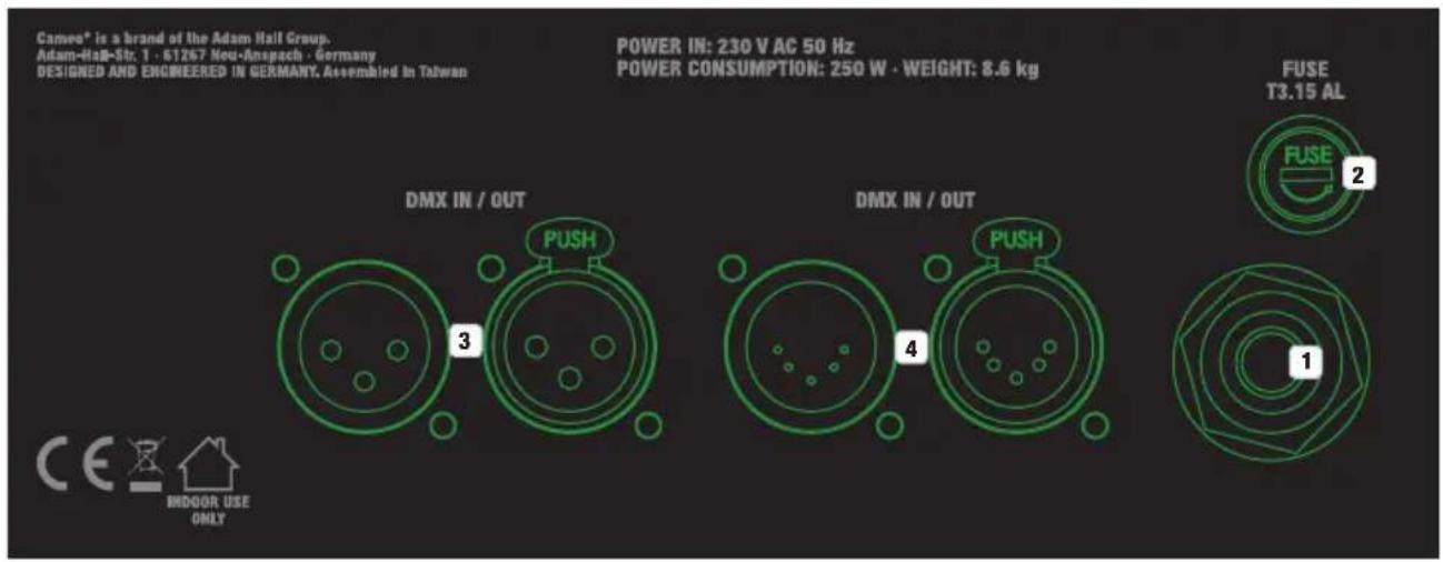
1 POWER IN
Permanently connected power cable with CEE 7/7 power plug.
2 FUSE
Fuse holder with fuse. IMPORTANT INFO: Replace the fuse only with a fuse of the same type and values according to the imprint on the device! If a fuse trips repeatedly, please contact an authorized service center.
3 DMX IN / OUT
3-pin XLR connector (male = IN / female = out) to connect a DMX control device and transmit the DMX control signal.
4 DMX IN / OUT
5-pin XLR connector (male = IN / female = out) to connect a DMX control device and transmit the DMX control signal.
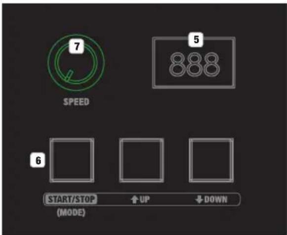
5 LED DISPLAY
The three-digit LED display shows the DMX address and menu options for manual control.
6 CONTROL KEYS
START/STOP (MODE): Starts and stops manual mode. Activates and deactivates control via RF remote control. UP and DOWN: Configure DMX address.

SPEED
Speed controller to set the fan speed in manual mode and when operating via RF remote control.
OPERATION
The device is ready to be used after being connected to the power supply. The control keys have back lighting, which switches on automatically when the keys are pressed and switches off automatically approx. 15 seconds after pressing said keys. If there is a pending DMX signal on the device, DMX mode will be forcibly activated. CAUTION: Never reach through the protective grille, there is a risk of injury! Never stick items through the protective grille! Special caution should be exercised by people with long hair; long hair can be drawn in and entangled in the fan, causing serious injury!
CONFIGURING DMX MODE
End manual mode as needed by pressing the START/STOP (MODE) button. If there is no DMX signal, the display will now show 3 minus signs; if there is a signal, the DMX address will display. Use the UP and DOWN keys to set the desired DMX address (001 - 512, hold the button for rapid value adjustment). The simultaneous control of multiple devices of the same model with a DMX control unit (e.g. DMX mixer) can be achieved by setting identical DMX start addresses on the devices and connecting them via DMX cables. You can find DMX tables on channel assignment in these instructions under DMX CONTROL.
MANUAL MODE
If there is a pending DMX signal on the device, manual operation will not be possible; the device must be disconnected from a DMX network. Now use the START/STOP button to activate manual mode (press briefly). Change the fan speed using knob no. 7 to 99 (turning left = minimum speed, turning right = maximum speed). To end manual mode, briefly press the START/STOP button again.
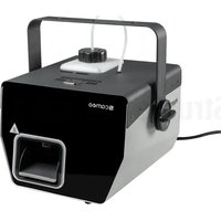
CONTROL VIA RF REMOTE CONTROL.
Separate the wind machine from a DMX network. Press and hold the START/STOP (MODE) button for a duration of approx. 5 seconds in order to activate RF remote control (point between 1st and 2nd position on the display illuminates). The provided RF remote control (433 MHz) has a sliding cover in order to protect the control keys from accidental activation. To this end, push the protective cover up over the control keys. Push the protective cover down to the catch in order to free the control keys and control the wind machine using the RF remote control. The LED on the control panel will illuminate as soon as one of the control keys is pressed. If the LED does not illuminate when pressing a key, the internal batteries must be replaced. To do so, remove the three screws on the rear side of the remote control (battery type: 27A, 12V). Deactivate RF remote control by pressing and holding the START/STOP (MODE) button for a duration of approx. 5 seconds (point between 1st and 2nd position on the display illuminates).
Control keys
A - start fan
B - stop fan
C - increase speed
D - decrease speed

natural_image
Two black remote control devices with attached keys and a red arrow labeled 'camoo' (no text or symbols on the devices themselves)SETUP
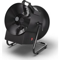
Thanks to the stable stand and the pre-mounted rubber feet, the wind machine can be placed on an even surface at a suitable location. The adjustment of the direction of radiation on the vertical plane is carried out with the help of the two wing screws on the side.
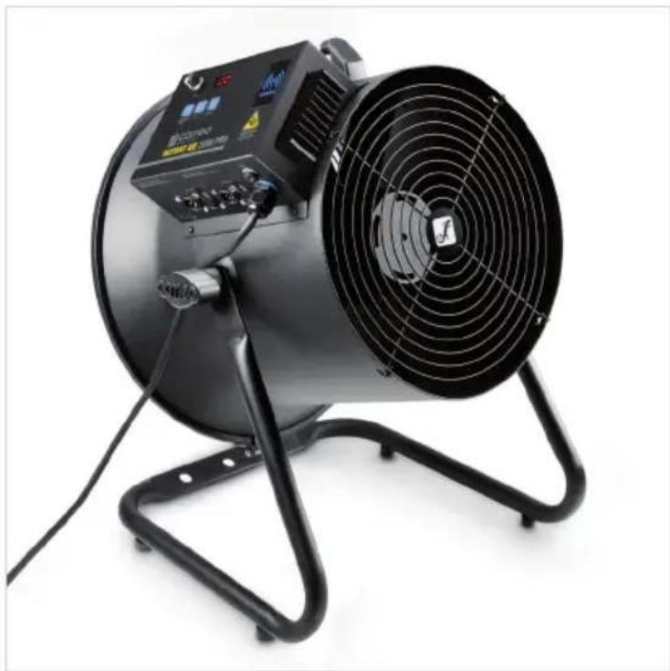
natural_image
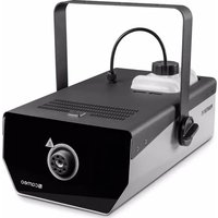
Exterior view of a black industrial fan with control panel and ventilation grille (no visible text or symbols)DMX TECHNOLOGY
DMX-512
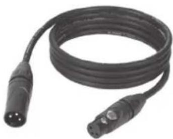
DMX (Digital Multiplex) is the designation for a universal transmission protocol for communications between corresponding devices and controllers. A DMX controller sends DMX data to the connected DMX device(s). The DMX data is always transmitted as a serial data stream that is forwarded from one connected device to the next via the "DMX IN" and "DMX OUT" connectors (XLR plug-type connectors) that are found on every DMX-capable device, provided the maximum number of devices does not exceed 32 units. The last device in the chain needs to be equipped with a terminator (terminating resistor).
natural_image
Coiled black cable with two connectors and a terminal pin (no text or symbols visible)DMX CONNECTION
DMX is the common "language" via which a very wide range of types and models of equipment from various manufacturers can be connected with one another and controlled via a central controller, provided that all of the devices and the controller are DMX compatible. For optimum data transmission, it is necessary to keep the connecting cables between the individual devices as short as possible. The order in which the devices are integrated in the DMX network has no influence on the addresses. Thus the device with the DMX address 1 can be located at any position in the (serial) DMX chain: at the beginning, at the end or somewhere in the middle. If the DMX address 1 is assigned to a device, the controller "knows" that it should send all data allocated to address 1 to this device regardless of its position in the DMX network.
SERIAL CONNECTION OF MULTIPLE LIGHTS
- Connect the male XLR connector (3-pin or 5-pin) of the DMX cable to the DMX output (female XLR socket) of the first DMX device (e.g. DMX-Controller).
- Connect the female 3-pin XLR connector of the DMX cable connected to the first projector to the DMX input (male 3-pin socket) of the next DMX device. In the same way, connect the DMX output of this device to the DMX input of the next device and repeat until all devices have been connected. Please note that as a rule, DMX devices are connected in series and connections cannot be shared without active splitters. The maximum number of DMX devices in a DMX chain should not exceed 32 units.
The Adam Hall 3 STAR, 4 STAR, and 5 STAR product ranges include an extensive selection of suitable cables.
DMX CABLES
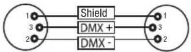
When fabricating your own cables, always observe the illustrations on this page. Never connect the shielding of the cable to the ground contact of the plug, and always make certain that the shielding does not come into contact with the housing of the XLR plug. If the shielding is connected to the ground, this can lead to short-circuiting and system malfunctions.
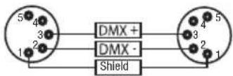
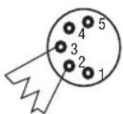
Pin Assignment
DMX cable with 3-pin XLR connectors: DMX cable with 5-pin XLR connectors (pin 4 and 5 are not used):
flowchart
graph LR
    A["1"] --> B["Shield"]
    C["3"] --> B
    D["2"] --> B
    B --> E["1"]
    B --> F["3"]
    B --> G["2"]
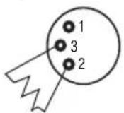
DMX TERMINATORS (TERMINATING RESISTORS)
To prevent system errors, the last device in a DMX chain needs to be equipped with a terminating resistor (120 ohm, 1/4 Watt).
3-pin XLR connector with a terminating resistor: K3DMXT3
5-pin XLR connector with a terminating resistor: K3DMXT5
Pin Assignment
3-pin XLR connector: 5-pin XLR connector:
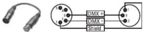
DMX ADAPTER
The combination of DMX devices with 3-pin connectors and DMX devices with 5-pin connectors in a DMX chain is possible with suitable adapters.
Pin Assignment
DMX Adapter 5-pin XLR male to 3-pin XLR female: K3DGF0020
Pins 4 and 5 are not used.
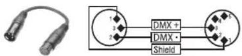
Pin Assignment
DMX Adapter 3-pin XLR male to 5-pin XLR female: K3DHM0020
Pins 4 and 5 are not used.
TECHNICAL SPECIFICATIONS
Item number: CLIA2000PRO
| Product type: Wind machine |
| Maximum air flow: 56 m3/min. |
| Air speed: 12 m/s |
| Fan speed: 440-2500 U/min |
| Fan diameter: 310 mm |
| DMX input: 3-pin XLR male |
| DMX output: 3-pin XLR female |
DMX mode: 1-channel
DMX functions: Fan control
Standalone functions: Fan control
Controller: DMX512, RF remote control
Control elements: START/STOP (MODE), UP, DOWN (backlit)
Display elements: 3-digit LED display
Operating voltage: 230V AC / 50Hz
Power consumption: 250W
Power supply connection: Permanently connected power cable with CEE 7/7 power plug
Fuse: T3.15AL / 250V (5 x 20 mm)
Ambient temperature in operation: 0^ - 40^
Relative humidity: < 85%, non-condensing
Housing material: Metal
Housing color: Black
Dimensions (∅ x H, with stand): 385 x 515mm
Weight: 8.6kg
Additional features: Handle, adjustable base included
MANUFACTURER'S DECLARATIONS
MANUFACTURER'S WARRANTY & LIMITATIONS OF LIABILITY
You can find our current warranty conditions and limitations of liability at: https://cdn-shop.adamhall.com/media/pdf/MANUFACTURERS-DECLARATIONS_CAMEO.pdf. To request warranty service for a product, please contact Adam Hall GmbH, Adam-Hall-Str. 1, 61267 Neu Anspach / Email: Info@adamhall.com / +49 (0)6081 / 9419-0.

CORRECT DISPOSAL OF THIS PRODUCT
(valid in the European Union and other European countries with a differentiated waste collection system)
This symbol on the product, or on its documents indicates that the device may not be treated as household waste. This is to avoid environmental damage or personal injury due to uncontrolled waste disposal. Please dispose of this product separately from other waste and have it recycled to promote sustainable economic activity. Household users should contact either the retailer where they purchased this product, or their local government office, for details on where and how they can recycle this item in an environmentally friendly manner. Business users should contact their supplier and check the terms and conditions of the purchase contract. This product should not be mixed with other commercial waste for disposal.
CE Compliance
Adam Hall GmbH states that this product meets the following guidelines (where applicable):
R&TTE (1999/5/EC) or RED (2014/53/EU) from June 2017
Low voltage directive (2014/35/EU)
EMV directive (2014/30/EU)
RoHS (2011/65/EU)
The complete declaration of conformity can be found at www.adamhall.com.
Furthermore, you may also direct your enquiry to info@adamhall.com.
DEUTSCH
natural_image
Two remote control devices with a car keychain, one displaying a red arrow and the other showing a black keypad (no text or symbols visible)AUFSTELLUNG
natural_image
Black industrial fan with visible control panel and mounting base (no text or symbols)DMX TECHNIK
DMX-512
natural_image
Coiled black cable with two connectors and a three-pin connector (no text or symbols visible)DMX-VERBINDUNG:
DMX-Adapter 5-Pol XLR male auf 3-Pol XLR female: K3DGF0020
natural_image
Two remote control devices with a car keychain, one showing a red arrow pointing to a camera labeled 'cameo' (no text or symbols on device body)INSTALLATION
natural_image
Black industrial fan with visible control panel and mounting base (no text or symbols)TECHNIQUE DMX
DMX-512
natural_image
Coiled black cable with two connectors and a terminal pin (no text or symbols visible)PROTOCOLE DMX
(Valid in the European Union and other European countries with waste separation)