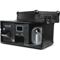
INSTANT HAZE 1500 T G2 - Effect machine Cameo - Free user manual and instructions
Find the device manual for free INSTANT HAZE 1500 T G2 Cameo in PDF.


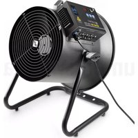
| Product type | Professional haze generator |
| Brand | Cameo |
| Model | INSTANT HAZE 1500 T G2 |
| Dimensions (W x H x D) | 585 × 273 × 450 mm |
| Weight (without fluid) | 20.4 kg |
| Power supply | 230 V / 50 Hz, 1500 W |
| Fuse type | F 10 AL / 250 V |
| DMX connectors | XLR 3-pin and XLR 5-pin (input/output) |
| DMX control | DMX512 on 2 channels |
| Control functions | Stand-alone, Timer, DMX, W-DMX (via optional iDMX dongle) |
| Display | Illuminated touch screen |
| Operating temperature | 5 °C to 45 °C |
| Tank capacity | 5-liter bottle (Cameo Haze Fluid) |
| Max. fluid flow rate | 9 ml/min at 100% |
| Heat-up time | Less than 1 minute |
| Safety distance (flammable materials) | 0.5 m |
| Protection class | IP20 |
| Housing material | Metal, integrated in a flight case |
| Usage | Floor placement only |
| Evaporation system cleaning | Every 60 hours with Cameo Cleaning Fluid (CLFCLEANER250) |
| Included accessories | Bottle cap with hose, mains cable, manual |
| Optional accessories | iDMX dongle, 5L fluid, cleaner |
Frequently Asked Questions - INSTANT HAZE 1500 T G2 Cameo
User questions about INSTANT HAZE 1500 T G2 Cameo
0 question about this device. Answer the ones you know or ask your own.
Ask a new question about this device
Download the instructions for your Effect machine in PDF format for free! Find your manual INSTANT HAZE 1500 T G2 - Cameo and take your electronic device back in hand. On this page are published all the documents necessary for the use of your device. INSTANT HAZE 1500 T G2 by Cameo.
USER MANUAL INSTANT HAZE 1500 T G2 Cameo
natural_image
Exterior view of a black COMO medical device with internal tubing and control panel (no visible text or symbols)INSTANT HAZE G2
CLIH1500TG2
CONTENTS / INHALTSVERZEICHNIS / CONTENU / CONTENIDO / TREŚĆ / CONTENUTO
ENGLISH
INFORMATION ON THIS USER MANUAL 6
INTENDED USE 6
EXPLANATIONS OF TERMS AND SYMBOLS 6
SAFETY INSTRUCTIONS 7
NOTES FOR PORTABLE INDOOR DEVICES 12
PACKAGING CONTENT 12
INTRODUCTION 12
CONNECTIONS AND OPERATING/DISPLAY ELEMENTS 13
OPERATION 15
ERROR MESSAGES 19
INSTALLATION 20
CARE, MAINTENANCE AND REPAIR 20
OPTIONAL ACCESSORIES 21
TECHNICAL DATA 22
DISPOSAL 23
MANUFACTURER'S DECLARATIONS 23
DEUTSCH
You have made the right choice!
This device has been developed and manufactured to the highest quality standards to ensure many years of trouble-free operation. Please read this user manual carefully to be able to quickly put your new Cameo Light product to optimum use. Further information about Cameo Light is available on our website CAMEOLIGHT.COM.
INFORMATION ON THIS USER MANUAL
- Carefully read the safety instructions and the entire manual before operating the device.
- Observe the warnings on the device and in the user manual.
• Always keep the user manual within reach. - If you sell or pass on the device, it is important that you also include this user manual, as it is an integral part of the product.
INTENDED USE
This product is a device for event technology.
This product has been developed for professional use in the field of event technology and is not suitable for use as domestic lighting.
Temporary operation. Event equipment is generally designed for temporary use only and not for continuous operation and fixed installation.
Furthermore, this product is only intended for qualified users with specialist knowledge of event technology.
Use of the product outside the specified technical data and operating conditions is considered improper use.
Liability for damage and third-party damage to persons and property due to inappropriate use is excluded.
The product is not suitable for:
- Persons (including children) with limited physical, sensory, or mental abilities or lack of experience and knowledge.
- Children (children must be instructed not to play with the device).
EXPLANATIONS OF TERMS AND SYMBOLS
- DANGER: The word DANGER, possibly in combination with a symbol, indicates immediately hazardous situations or conditions for life and limb.
- WARNING: The word WARNING, possibly in combination with a symbol, indicates potentially hazardous situations or conditions for life and limb.
- CAUTION: The word CAUTION, possibly in combination with a symbol, indicates situations or conditions that may lead to injury.
- ATTENTION: The word ATTENTION, possibly in combination with a symbol, indicates situations or conditions that may lead to damage to property and/or the environment.

This symbol identifies hazards that can cause electric shock.

This symbol indicates hazardous areas or hazardous situations.

This symbol indicates hazards caused by hot surfaces.

This symbol indicates hazards due to suspended loads.

This symbol indicates a device in which there are no user-serviceable parts.

This symbol indicates additional information on the operation of the product.

This symbol indicates a device that may only be used in dry rooms.
SAFETY INSTRUCTIONS

DANGER:
- Do not open or modify the device.
- If your device stops working properly, or if liquids or objects get inside it, or it is damaged in any other way, switch it off immediately and disconnect it from the power supply. The device may be repaired only by authorised repair technicians.
- For devices of protection class 1, the protective conductor must be connected correctly. Never disconnect the protective conductor. Devices of protection class 2 do not have a protective conductor.
- Ensure that live cables are not kinked or otherwise mechanically damaged.
- Never bypass the device fuse.

WARNING:
- The device should not be operated if it shows obvious signs of damage.
- The device may only be installed in a voltage-free state.
- If the mains cable of the device is damaged, do not operate the device.
- Permanently attached mains cables may only be replaced by a qualified person.

ATTENTION:
- Do not operate the device if it has been exposed to large temperature fluctuations (for example, after transport). Moisture and condensation may damage the device. Switch on the device only when it has reached ambient temperature.
- Make sure that the voltage and frequency of the mains correspond to the values specified on the device. If the device has a voltage selector switch, do not turn the device on until it has been set correctly. Use only suitable mains cables.
- To completely disconnect the device from the mains, it is not enough to press the on/off switch on the device.
- Make sure that the fuse used corresponds to the type specified on the device.
- Make sure that appropriate measures have been taken against power surges (for example, lightning strike).
- Observe the specified maximum output current on devices with Power Out connection. Ensure that the total current consumption of all connected devices does not exceed the specified value.
- Replace plug-in mains cables only with original cables.
- Connect the device only to compliant, tested, and undamaged mains connections.

DANGER:
- Danger of suffocation/choking! Plastic bags and small parts must be kept out of reach of persons (including children) with reduced physical, sensory, or mental capabilities.
- Danger caused by the device falling! Make sure that the device is securely installed and cannot fall down. Only use suitable stands or mounts (particularly for fixed installations). Ensure that accessories are properly installed and secured. Ensure that all applicable safety regulations are observed.

WARNING:
- Use the device only in the prescribed manner.
- Operate the device only with the accessories recommended and intended by the manufacturer.
- During installation, observe the safety regulations applicable in your country.
- After connecting the device, check all cable routes to avoid damage or accidents, for example, due to trip hazards.
- Always observe the specified minimum distance from normally flammable materials! If this is not explicitly stated, the minimum distance is 0.3 metres.

CAUTION:
- Moving components such as mounting brackets or other movable components may become jammed.
- Devices with motor-driven components may cause injury due to the movement of the device. Sudden movement of the device can cause shock reactions.

- The exterior surface of the device can become very hot during regular operation. Ensure that it is not possible to accidentally touch the housing. Always allow the device to cool sufficiently before removal, maintenance work, charging, or similar.

ATTENTION:
- Do not install or operate the device in the vicinity of radiators, heat accumulators, furnaces, or other heat sources. Ensure that the device is always installed in such a way that it is sufficiently cooled and cannot overheat.
- Do not place ignition sources such as burning candles near the device.
- Ventilation openings must not be covered, and fans must not be blocked.
- Use the original packaging or packaging provided by the manufacturer for transport.
- Avoid shock or impact to the device.
- Observe the IP protection class, as well as the ambient conditions such as temperature and humidity, according to the specification.
- Devices can be continuously further developed. In case of deviating information on operating conditions, performance, or other device properties between the user manual and the device labelling, the information provided on the device always has priority.
- The device is not suitable for tropical climates or for operation over 2000 m above sea level.
- Unless explicitly stated, the device is not suitable for operation in marine conditions.

PLEASE NOTE:
For conversion or retrofit sets, or accessories provided by the manufacturer, it is essential to observe the included instructions.

RADIO SIGNAL TRANSMISSION (FOR EXAMPLE, W-DMX OR AUDIO RADIO SYSTEMS):
The quality and performance of wireless signal transmissions generally depends on the ambient conditions.
For example, the following factors can impact range and signal stability:
Shielding (for example, masonry, metal structures, water)
High volumes of radio traffic (for example, powerful wireless LAN networks)
Interference
Electromagnetic radiation (for example, LED video screens, dimmers)
All range specifications refer to free-field line-of-sight applications without interference.
The operation of radio transmission systems is subject to official regulations. These may vary from region to region and must be checked by the operator before use (for example, radio frequency and transmission power).

WARNING: Devices with wireless signal transmission are not suitable for use in sensitive areas in which radio operation can lead to potential detrimental effects. These include:
- Hospitals, health centres, or other healthcare facilities that provide patient treatments with skilled personnel and equipment.
• Class I, II, and III hazardous areas - Restricted areas
- Military facilities
- Aircraft or vehicles
- Areas where the use of mobile phones is prohibited

TRANSMISSION VIA W-DMX
WARNING: In general, wireless DMX transmission must not be used for applications involving safety-related factors that might result in personal injury or property damage in case of a failure.
This applies in particular to moving scene or truss structures, DMX-controlled motors/lifts, or lifting devices for operating DMX-operated platform lifts, hydraulic systems, or comparable moving components.
Furthermore, wireless DMX transmission must not be used to control flame or pyrotechnic devices, explosion-driven effects, or gas or liquid effects. These include CO ^2 cannons, confetti shooters, water effects, or similar.

CAUTION! IMPORTANT INFORMATION REGARDING FOG MACHINES AND HAZE GENERATORS!
- Only use water-based Cameo fog fluid (for fog machines) or Cameo Instant Haze Fluid (for haze generators) and never add flammable liquid to the container! Danger of explosion!
- Disconnect the fog machine or the haze generator from the mains before changing the canister or topping up the fluid! Make sure that no fluid gets into the housing during filling. If fluid gets into the device housing, the device must not be put into operation under any circumstances.
- Operate the fog machine or haze generator only in well-ventilated rooms!
- Never leave the fog machine or haze generator running unattended!
- Disconnect the fog machine or haze generator from the mains before setting up and assembling or dismantling and stowing away, and ensure that the fog machine or haze generator has cooled down completely.
- The fog or haze outlet nozzle becomes very hot during operation. Do not touch the outlet nozzle during operation and maintain a minimum distance of 50 cm from it! Ensure that the device has cooled down completely before cleaning or transporting it!
- The fog or haze emitted is very hot. Never direct the outlet nozzle towards people or animals. RISK OF BURNING!
- If the fog machine or haze generator is installed overhead, ensure that people or animals are not allowed directly underneath it. RISK OF BURNING!
- Never direct the outlet nozzle towards open flames or flammable materials.
- Ensure that other electrical devices and sockets are never exposed to the direct fog jet or haze.
- During operation, condensate can collect in front of the outlet nozzle. Caution, danger of slipping!
- Occasionally, small amounts of fog or haze may escape during operation, even without activation, and also for a short time after the device has been switched off.
- Never expose people with respiratory diseases (e.g. allergy sufferers, asthmatics) to artificial fog or haze.
- When using fog machines and haze generators, make sure that the visibility in the room does not fall below approx. 2 metres so that people in the room can still orient themselves safely.
- Remove the fluid canister from the fog machine or haze generator before transporting.
- Escaping fog or haze can trigger smoke alarms.
- Keep out of the reach of children!

NOTES FOR PORTABLE INDOOR DEVICES
- Temporary operation! Event equipment is generally only designed for temporary operation.
- Continuous operation or permanent installation can impair the functionality of the device and cause premature ageing.
PACKAGING CONTENT
Remove the product from the packaging, and remove all packaging material.
Please check the completeness and integrity of the delivery, and notify your distribution partner immediately after purchase if the delivery is not complete or if it is damaged.
The packaging content for the product includes:
▶ 1 × Instant Haze 1500T G2 haze generator integrated in the road case
▶ 1 × canister cap with suction pipe, filter and ventilation valve
▶ 1 × mains cable
▶ Safety and compliance information (user manual as a download via QR code)
INTRODUCTION
INSTANT HAZE 1500T G2
CONTROL FUNCTIONS:
2-channel DMX control
DMX512
Wireless DMX via optionally available Cameo iDMX stick
Stand-alone function
Timer function
FEATURES:
Device integrated into the road case. DMX512. 3- and 5-pin DMX connections. Connection for optional iDMX stick for wireless control via wireless DMX.
CONNECTIONS AND OPERATING/DISPLAY ELEMENTS
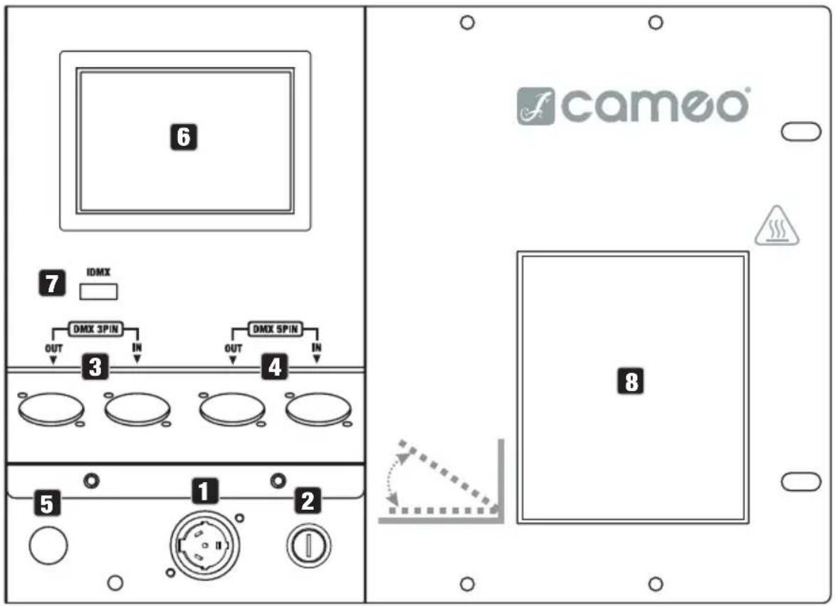
1 POWER IN
Mains input socket. Operating voltage: 230 V AC/50 Hz. Connect using the supplied mains cable.
2 FUSE
Fuse holder for 5 × 20 mm fuses. IMPORTANT NOTE: Only replace the fuse with a fuse of the same type and value. If the fuse repeatedly fails, please contact an authorised service centre.
3 DMX 3 PIN
One male and one female 3-pin XLR socket for connecting a DMX control device (IN) and for forwarding the DMX signal (OUT).
4 DMX 5 PIN
One male and one female 5-pin XLR socket for connecting a DMX control device (IN) and for forwarding the DMX signal (OUT).
5 HOSE CONNECTION
Permanently connected fluid hose.
6 TOUCH DISPLAY
Illuminated touch display for navigating the device menu.
7 IDMX
Connection for the optionally available iDMX stick for wireless DMX operation.
8 HAZE OUTLET
Haze outlet with manually adjustable guide plate.

Only use the DMX inputs (3-pin XLR, 5-pin XLR, iDMX) and the DMX outputs (3-pin XLR, 5-pin XLR) as alternatives.
CANISTER DRAWER AND SPECIAL CAP FOR CANISTERS
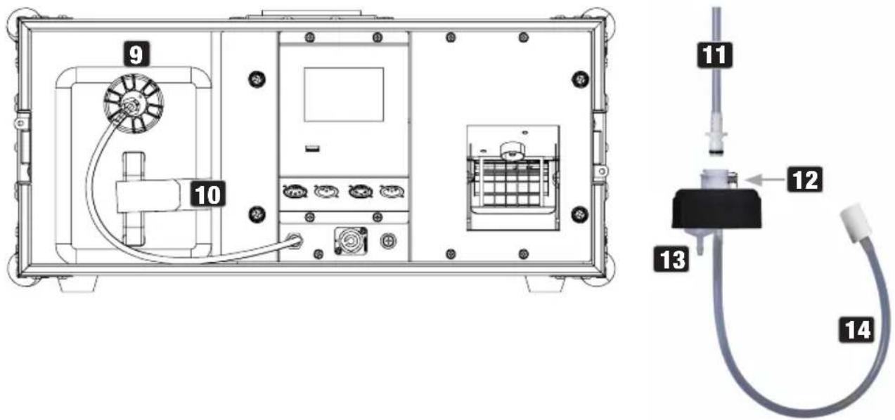
9 CANISTER DRAWER
Canister drawer for a 5-litre canister of Cameo haze fluid.
10 VELCRO STRAP
Velcro strap for attaching the fluid canister.
11 FLUID HOSE
The fluid hose, equipped with a nozzle and a black sealing ring, is firmly connected to the device. Connect the fluid hose to the special cap by inserting the hose nozzle into the quick coupler until the locking mechanism engages. Check that the connection is secure.
12 RELEASE BUTTON
To detach the fluid hose from the special cap, press the spring-loaded release button on the quick coupler.
13 VENTILATION VALVE
Ventilation valve to prevent negative pressure.
14 SUCTION PIPE
Suction pipe with filter.
INSERTING AND CONNECTING FLUID CANISTER
Before inserting or replacing a canister, completely disconnect the haze generator from the mains (pull out the mains plug).
A special canister cap with suction pipe and ventilation valve, suitable for 5-litre Cameo haze fluid canisters, is included in the packaging content (canister not included).
Place a Cameo haze fluid canister upright in front of the haze generator and unscrew the canister cap. Insert the suction pipe of the enclosed special cap into the canister and screw the cap onto the canister. The filter on the suction pipe ensures that dirt particles do not enter the system and that the end of the pipe sinks downwards. Now connect the fluid hose of the haze generator to the special cap. Push the canister into the canister compartment and secure it with the Velcro strap.
OPERATION

PLEASE NOTE
When the device is first started up, noise may occur until the haze fluid has displaced the air from the system. This process typically takes about one minute to complete. Only disconnect the haze generator from the mains after you have reduced the haze generation to zero (via DMX) or ended manual operation, and no more haze is emitted (auto-cleaning function).
NOTES
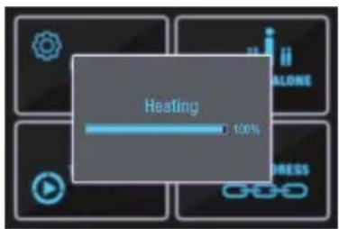
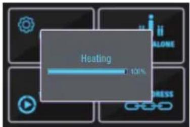
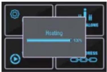
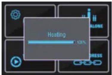
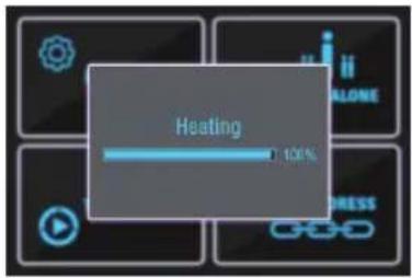
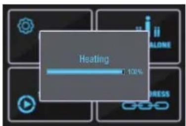
Never operate the haze generator without haze fluid! After the haze generator is switched on, a brief system check is performed, and the serial designation is displayed on the screen. After this process, the evaporator is heated up (heating). After a short time, the operating temperature is reached, and the haze generator is ready for use.

flowchart
graph TD
    A["MENU"] --> B["STAND ALONE"]
    C["TIMER"] --> D["DMX ADDRESS"]
    E["User icon"] --> A
    F["Link icon"] --> C
    G["Link icon"] --> E
MAIN DISPLAY (DMX SIGNAL PRESENT)
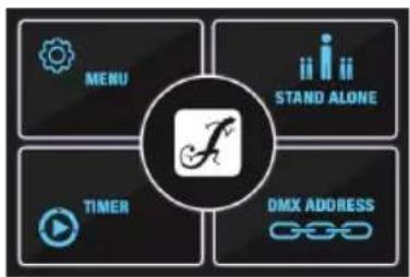
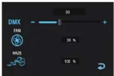
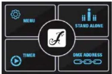
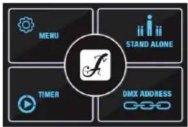
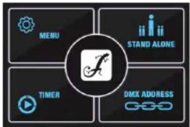
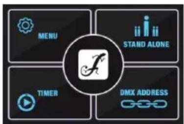
As soon as a DMX signal is present at one of the DMX inputs DMX IN or the wireless interface iDMX, the DMX operating mode is automatically activated, and the window with the current DMX start address and the values set via the DMX controller for the fan speed FAN and the haze quantity HAZE are displayed.
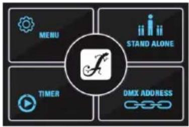
MAIN DISPLAY (NO DMX SIGNAL)
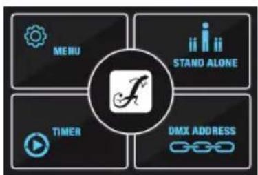
If the DMX signal is interrupted, the display automatically switches to the main display.
flowchart
graph TD
    A["MENU"] --> B["STAND ALONE"]
    C["TIMER"] --> D["DMX ADDRESS"]
    E["User icon"] --> A
    F["Link icon"] --> C
    G["Play button"] --> C
SET DMX START ADDRESS
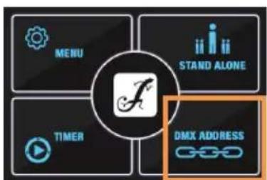
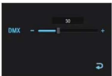
From the main display, tap the DMX ADDRESS button. Now set the desired DMX start address using the virtual fader or by tapping + and -. Tap the arrow symbol to return to the main display.
flowchart
graph TD
    A["MENU"] --> B["STAND ALONE"]
    C["TIMER"] --> D["DMX ADDRESS"]
    E["F"] --> A
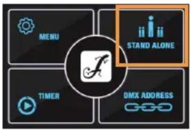
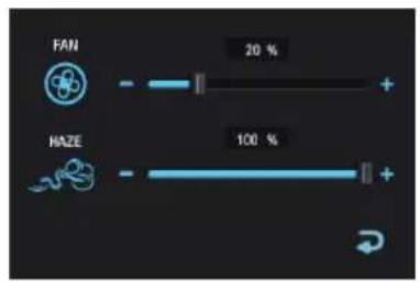
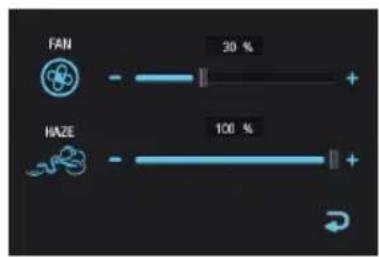
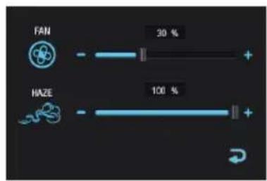
From the main display, tap the STAND ALONE button. Now set the fan speed FAN and the haze volume HAZE as required using the virtual fader or by tapping + and -. Tap the arrow symbol to end stand-alone operation and return to the main display.
flowchart
graph TD
    A["MENU"] --> B["TIMER"]
    B --> C["DMX ADDRESS"]
    C --> D["STAND ALONE"]
    D --> E["Central Function Icon"]
SET TIMER AND HAZE
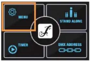
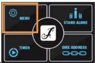
From the main display, tap the MENU button.
flowchart
graph TD
    A["MENU"] --> B["STAND ALONE"]
    C["TIMER"] --> D["DMX ADDRESS"]
    E["Link"] --> F["Function Icon"]
    style A fill:#f9f,stroke:#333
    style B fill:#ccf,stroke:#333
    style C fill:#cfc,stroke:#333
    style D fill:#fcc,stroke:#333
    style E fill:#ffc,stroke:#333
    style F fill:#fcc,stroke:#333
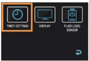
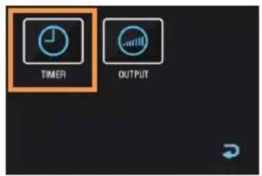
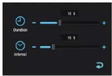
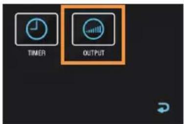
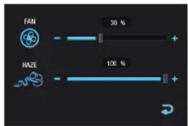
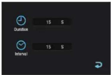
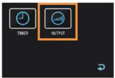
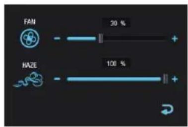
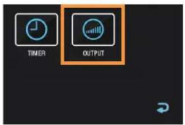
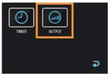
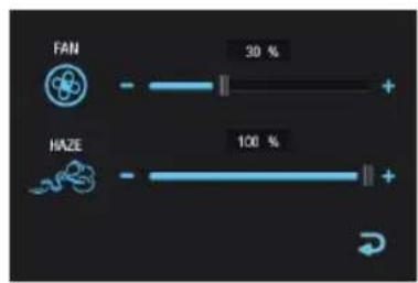
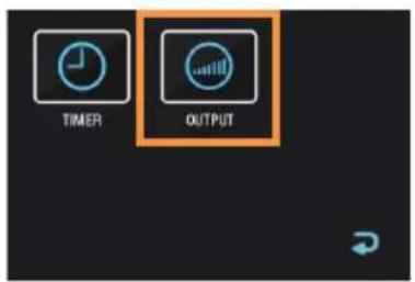
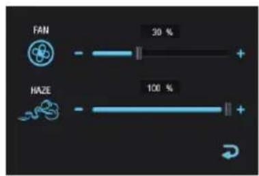
Tap TIMER SETTINGS, then TIMER and set the Duration and Interval as required using the virtual faders or by tapping + and -. Tap the arrow symbol to return to the previous display. Now tap OUTPUT and set the fan speed FAN and the haze volume HAZE as required using the virtual fader or by tapping + and -. Tap the arrow symbol to return to the previous display.
ACTIVATE TIMER
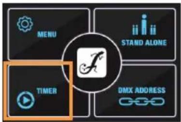
From the main display, tap the TIMER button. The Timer operating mode is now activated, and the previously set Duration and Interval are displayed on the screen.
Tap the arrow symbol to end the Timer operating mode and return to the main display.
flowchart
graph TD
    A["MENU"] --> B["STAND ALONE"]
    C["TIMER"] --> D["DMX ADDRESS"]
    E["User icon"] --> F["Link link"]
SWITCHING THE FLUID LEVEL SENSOR OFF AND ON
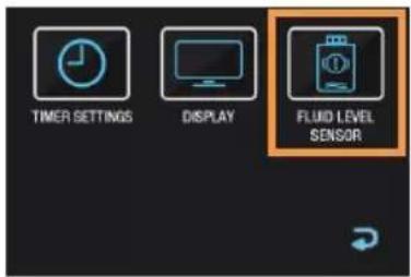
The fluid level sensor should always be switched on during normal operation. Only in exceptional cases does it make sense to switch the sensor off for a short time (e.g. for servicing purposes).
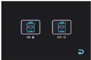
From the main display, tap the MENU button. Then tap FLUID LEVEL SENSOR. You can now read the current status and change it if necessary by tapping the corresponding symbol (ON = sensor switched on, OFF = sensor switched off). Tap the arrow symbol in the corresponding window to return to the previous display.

flowchart
graph TD
    A["MENU"] --> B["TIMER"]
    B --> C["DMX ADDRESS"]
    D["STAND ALONE"] --> E["User icon"]
    F["Central icon with key symbol"] --> A
DISPLAY SETTINGS
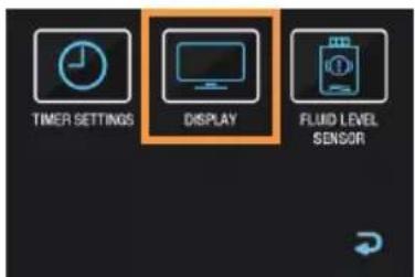
From the main display, tap the MENU button. Then tap DISPLAY.
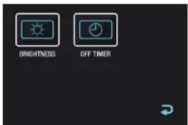
Tap BRIGHTNESS to adjust the display brightness using the virtual fader or by tapping + and -. Tap OFF TIMER to set the status of the display backlighting:
Always on = display lighting is permanently switched on
OFF after 20 s = display lighting is switched off after approx. 20 seconds without input.
Tap the arrow symbol in the corresponding window to return to the previous display.
flowchart
graph TD
    A["MENU"] --> B["STAND ALONE"]
    C["TIMER"] --> D["DMX ADDRESS"]
    E["LOGIC LINE"] --> F["FUNCTION"]
ERROR MESSAGES
| Error message | Meaning Description | Solution | |
| No Liquid! | No liquid (canister empty) | As soon as the fluid canister is empty, the pump and heating element are switched off for protection. | 1. Switch off the device and disconnect it from the power supply.2. Refill the fluid canister.3. Reconnect the device to the power supply and switch it on. The haze generator is now ready for operation again after the heating-up phase. If “No Liquid!” continues to be displayed, take the device out of operation and contact your distribution partner. |
| Heating up! | Heating up | During a heating-up phase, the haze generator is not operational. | Wait until the operating temperature has been reached again, and “Heating up!” is no longer displayed. |
| Temperature Error! | Temperature error | If the heating element cannot heat up correctly or overheats, the temperature error message is displayed. Reason:- Fluid used up, heating element still heating.- Failure or damage to the main control board | If “Temperature error!” continues to be displayed even after restarting the device, take it out of operation and contact your distribution partner. |
| Sensor error! | Sensor error | The heating element or the main control board could have failed or been damaged. | If “Sensor error!” continues to be displayed even after restarting the device, take it out of operation and contact your distribution partner. |
| Thermocouple wire OFF! | Cable connection interrupted | The cable connection between the heating element and the main control board could be interrupted. | If “Thermocouple wire OFF!” continues to be displayed even after restarting the device, take it out of operation and contact your distribution partner. |
| Data error! | Data error | The cable connection between the control panel and the main control board could be interrupted. | If “Data error!” continues to be displayed even after restarting the device, take it out of operation and contact your distribution partner. |
INSTALLATION

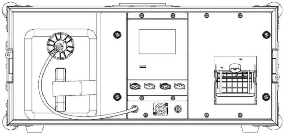
The Cameo IH1500TG2 haze generator is a floor-standing unit and must not be mounted overhead, as it does not have anchor points or safety eyes.
The device features four rubber feet on its underside, allowing it to be set up in a suitable spot on a level surface. When setting up the haze generator, please refer to the points under “CAUTION! IMPORTANT INFORMATION REGARDING FOG MACHINES AND HAZE GENERATORS!” in the safety instructions in this manual.
Make sure that the air intake grille on the side of the device is not covered and that air can be drawn in freely. Make sure that no dirt, sand, etc. can be sucked in.
natural_image
Technical line drawing of a mechanical device front view with internal components and wiring (no text or symbols)CARE, MAINTENANCE AND REPAIR
To ensure the long-term proper functioning of the device, it must be regularly cleaned and, if necessary, serviced. The servicing requirement depends on the intensity of use and the environment in which it is used.
A visual inspection should be carried out before each commissioning. In particular, all safety-relevant components, such as connecting elements, safety points, electrical connections and cables, must be taken into account. Furthermore, we recommend carrying out all applicable maintenance measures specified below at least once every 500 operating hours, or at the latest, after one year, if the device is not used frequently. Cleaning the evaporator system requires a significantly shorter maintenance interval (see CLEANING THE EVAPORATOR SYSTEM). Warranty claims may be limited should defects result from inadequate service and maintenance.
CARE (can be performed by the user)

WARNING! Before carrying out any care or maintenance, the power supply – and, if possible, all device connections – must be disconnected.

PLEASE NOTE! Improper care can lead to impairment or even destruction of the device.
- Housing surfaces must be cleaned with a clean, damp cloth. Make sure that no moisture can penetrate the device.
- Air inlets and outlets must be regularly cleaned of dust and dirt. If compressed air is used, make sure that damage to the device is prevented (for example, fans must be blocked in this case).
- Cables and connectors must be cleaned regularly, and dust and dirt must be removed.
- In general, no cleaning agents or abrasive agents may be used; otherwise, the surface finish may be damaged.
- Devices must be stored in a dry environment and protected from dust and dirt.
CLEANING THE EVAPORATOR SYSTEM
The evaporator system of fog machines and haze generators should be cleaned approximately every 60 hours of operation to prevent deposits from building up. To clean the evaporator system, we recommend using the Cameo cleaning fluid with product number CLFCLEANER250. Follow the instructions on the container.
MAINTENANCE AND REPAIR (qualified personnel only)

DANGER! There are live components in the device. Even after disconnecting from the mains, there may still be residual voltage in the device, for example, due to charged capacitors.

PLEASE NOTE! There are no user-serviceable assemblies in the device.

PLEASE NOTE! Maintenance and repair work may only be carried out by qualified specialist personnel authorised by the manufacturer. If in doubt, consult the manufacturer.

PLEASE NOTE! Improperly performed maintenance work may affect warranty claims.
OPTIONAL ACCESSORIES
CLIDMXSTICKG2 CLFIH5L CLFCLEANER250
Wireless DMX receiver Instant haze fluid, 5 litres Cameo cleaning fluid
TECHNICAL DATA
| Item number | CLIH1500TG2 |
| Product type | Hazer with microprocessor control |
| Max fluid consumption at 100% output | 9 ml / min |
| Heatup time | <1 min |
| DMX In / Out | XLR-3-pin male + XLR-5-pin male, XLR-3-pin female + XLR-5-pin female, iDMX stick (optional) |
| DMX functions | Fan speed, Haze output |
| Control | DMX512 |
| Standalone functions | Stand Alone (fan + haze), Timer function |
| Operating voltage | 230 V AC / 50 Hz |
| Power consumption | 1500 W |
| Inrush current | 32 A / 0.03 ms @ 230 V (first-half-cycle) |
| Fuse | F 10 AL / 250 V |
| Power connector | Powercon TR1 |
| Ambient temperature (operating) | 5°C ... 45°C |
| Housing colour | Black powder coated |
| Housing material | metal integrated in touring case |
| Protection class | IP 20 |
| Operating position | Only floor installation |
| Minimum distance from normally flammable materials | 0.5 m |
| Housing dimensions with lid (w x h x d) | 585 x 273 x 450 mm |
| Weight without fluid | 20.4 kg |
| Accessories (included) | Power cable, Canister connection cap |
| Accessories (optional) | CLIDMXSTICKG2, CLINSTANTHAZE5L, CLFCLEANER250 |
DISPOSAL

PACKAGING:
- Packaging can be recycled using the usual disposal methods.
- Please separate the packaging in accordance with the disposal laws and recycling regulations in your country.

DEVICE:
- This device is subject to the European Directive on Waste Electrical and Electronic Equipment, as amended. WEEE Directive Waste Electrical and Electronic Equipment. Waste equipment does not belong in household waste. Waste equipment must be disposed of via an authorised waste disposal company or a municipal waste disposal facility. Please observe the applicable regulations in your country!
- Observe all disposal laws and regulations applicable in your country.
- As a private customer, you can get information on environmentally-friendly disposal options from the seller of the product or the appropriate regional authorities.
MANUFACTURER'S DECLARATIONS
Manufacturer's warranty and limitation of liability
Adam Hall GmbH | Adam-Hall-Str. 1 | 61267 Neu Anspach | Germany
Email: Info@adamhall.com / +49 (0)6081 / 9419-0
Our current warranty conditions and limitation of liability can be found at:
https://cdn-shop.adamhall.com/media/pdf/Manufacturers-Declarations-CAMEO_DE_EN_ES_FR.pdf
For service requests, please contact your distribution partner.
EC conformity
Adam Hall GmbH hereby confirms that this product meets the following guidelines
(if applicable):
Low-Voltage Directive (2014/35/EU)
EMC Directive (2014/30/EU)
RoHS Directive
Radio Equipment Directive
EC Declaration of Conformity
Declarations of conformity for the products subject to the Low-Voltage Directive, the EMC Directive, and the RoHS Directive can be requested at: info@adamhall.com.
Declarations of conformity for products subject to RED can be downloaded from www.adamhall.com/compliance/.
Subject to misprints and errors, as well as technical or other modifications.
DEUTSCH
9 KANISTERFACH
flowchart
graph TD
    A["MENU"] --> B["STAND ALONE"]
    C["TIMER"] --> D["DMX ADDRESS"]
    E["User icon"] --> A
    F["Link icon"] --> C
    G["Link icon"] --> E
HAUPTANZEIGE (DMX-SIGNAL LIEGT AN)

TIMER AKTIVIEREN
FLUID LEVEL SENSOR AUS- BZW. EINSCHALTEN
natural_image
Technical line drawing of a mechanical device with internal components and wiring (no text or symbols)https://cdn-shop.adamhall.com/media/pdf/Manufacturers-Declarations-CAMEO_DE_EN_ES_FR.pdf
flowchart
graph TD
    A["MENU"] --> B["STAND ALONE"]
    C["TIMER"] --> D["DMX ADDRESS"]
    E["User icon"] --> A
    F["Link icon"] --> C
    G["Cross icon"] --> B
ÉCRAN PRINCIPAL (SIGNAL DMX PRÉSENT)
ACTIVER LA MINUTERIE
ACTIVER/DÉSACTIVER LE CAPTEUR DE NIVEAU DE LIQUIDE
natural_image
Technical line drawing of a mechanical device front view with internal components and wiring (no text or symbols)ENTRETIEN, MAINTENANCE ET RÉPARATION
https://cdn-shop.adamhall.com/media/pdf/Manufacturers-Declarations-CAMEO_DE_EN_ES_FR.pdf
Directive CEM (2014/30/UE)
Directive RoHS
flowchart
graph TD
    A["MENU"] --> B["STAND ALONE"]
    C["TIMER"] --> D["DMX ADDRESS"]
    E["User icon"] --> B
    F["Link icon"] --> D
PANTALLA PRINCIPAL (CON SEÑAL DMX)
ACTIVAR Y DESACTIVAR EL SENSOR DE NIVEL DE LÍQUIDO
natural_image
Technical line drawing of a mechanical device front view with internal components and wiring (no text or symbols)9 SZUFLADA NA KANISTER
13 ZAWÓR WENTYLACYJNY
flowchart
graph TD
    A["MENU"] --> B["STAND ALONE"]
    C["TIMER"] --> D["DMX ADDRESS"]
    E["User icon"] --> B
    F["Link icon"] --> D
WYŚWIETLACZ GŁÓWNY (SYGNAŁ DMX OBECNY)
AKTYWACJA TIMERA
WYŁACZANIE I WŁACZANIE CZUJNIKA POZIOMU PŁYNU
natural_image
Technical line drawing of a mechanical device front view with internal components and wiring (no text or symbols)PIELEGNACJA, KONSERWACJA I NAPRAWA
https://cdn-shop.adamhall.com/media/pdf/Manufacturers-Declarations-CAMEO_DE_EN_ES_FR.pdf
flowchart
graph TD
    A["MENU"] --> B["STAND ALONE"]
    C["TIMER"] --> D["DMX ADDRESS"]
    E["LOGIC LINE"] --> F["User Icon"]
    style A fill:#f9f,stroke:#333
    style B fill:#ccf,stroke:#333
    style C fill:#cfc,stroke:#333
    style D fill:#fcc,stroke:#333
    style E fill:#ffc,stroke:#333
    style F fill:#fcc,stroke:#333
DISPLAY PRINCIPALE (SEGNALE DMX PRESENTE)
ATTIVARE IL TIMER
SPEGNERE E ACCENDERE IL SENSORE DI LIVELLO DEL LIQUIDO
natural_image
Technical line drawing of a device rear panel with internal components and wiring (no text or symbols)https://cdn-shop.adamhall.com/media/pdf/Manufacturers-Declarations-CAMEO_DE_EN_ES_FR.pdf
- INSTANT HAZE G2
- CONTENTS / INHALTSVERZEICHNIS / CONTENU / CONTENIDO / TREŚĆ / CONTENUTO
- ENGLISH
- DEUTSCH
- INFORMATION ON THIS USER MANUAL
- INTENDED USE
- EXPLANATIONS OF TERMS AND SYMBOLS
- SAFETY INSTRUCTIONS
- DANGER:
- WARNING:
- ATTENTION:
- CAUTION:
- PLEASE NOTE:
- RADIO SIGNAL TRANSMISSION (FOR EXAMPLE, W-DMX OR AUDIO RADIO SYSTEMS):
- TRANSMISSION VIA W-DMX
- CAUTION! IMPORTANT INFORMATION REGARDING FOG MACHINES AND HAZE GENERATORS!
- NOTES FOR PORTABLE INDOOR DEVICES
- PACKAGING CONTENT
- INTRODUCTION
- CONTROL FUNCTIONS:
- FEATURES:
- CONNECTIONS AND OPERATING/DISPLAY ELEMENTS
- POWER IN
- FUSE
- DMX 3 PIN
- DMX 5 PIN
- HOSE CONNECTION
- TOUCH DISPLAY
- IDMX
- HAZE OUTLET
- CANISTER DRAWER
- VELCRO STRAP
- FLUID HOSE
- RELEASE BUTTON
- VENTILATION VALVE
- SUCTION PIPE
- INSERTING AND CONNECTING FLUID CANISTER
- OPERATION
- PLEASE NOTE
- NOTES
- MAIN DISPLAY (DMX SIGNAL PRESENT)
- MAIN DISPLAY (NO DMX SIGNAL)
- SET DMX START ADDRESS
- SET TIMER AND HAZE
- ACTIVATE TIMER
- SWITCHING THE FLUID LEVEL SENSOR OFF AND ON
- DISPLAY SETTINGS
- INSTALLATION
- CARE, MAINTENANCE AND REPAIR
- CARE (can be performed by the user)
- CLEANING THE EVAPORATOR SYSTEM
- MAINTENANCE AND REPAIR (qualified personnel only)
- OPTIONAL ACCESSORIES
- CLIDMXSTICKG2 CLFIH5L CLFCLEANER250
- DISPOSAL
- PACKAGING:
- DEVICE:
- MANUFACTURER'S DECLARATIONS
- Manufacturer's warranty and limitation of liability
- EC conformity
- EC Declaration of Conformity
- KANISTERFACH
- HAUPTANZEIGE (DMX-SIGNAL LIEGT AN)
- TIMER AKTIVIEREN
- FLUID LEVEL SENSOR AUS- BZW. EINSCHALTEN
- ÉCRAN PRINCIPAL (SIGNAL DMX PRÉSENT)
- ACTIVER LA MINUTERIE
- ACTIVER/DÉSACTIVER LE CAPTEUR DE NIVEAU DE LIQUIDE
- ENTRETIEN, MAINTENANCE ET RÉPARATION
- PANTALLA PRINCIPAL (CON SEÑAL DMX)
- ACTIVAR Y DESACTIVAR EL SENSOR DE NIVEL DE LÍQUIDO
- SZUFLADA NA KANISTER
- ZAWÓR WENTYLACYJNY
- WYŚWIETLACZ GŁÓWNY (SYGNAŁ DMX OBECNY)
- AKTYWACJA TIMERA
- WYŁACZANIE I WŁACZANIE CZUJNIKA POZIOMU PŁYNU
- PIELEGNACJA, KONSERWACJA I NAPRAWA
- DISPLAY PRINCIPALE (SEGNALE DMX PRESENTE)
- ATTIVARE IL TIMER
- SPEGNERE E ACCENDERE IL SENSORE DI LIVELLO DEL LIQUIDO
Brand : Cameo
Model : INSTANT HAZE 1500 T G2
Category : Effect machine