
ColorLogic II - Lighting HAYWARD - Free user manual and instructions
Find the device manual for free ColorLogic II HAYWARD in PDF.

| Product type | Submersible LED pool light |
| Brand | Hayward |
| Model | ColorLogic II |
| References | 3429LEDBL, 3424LEDBL (white), 3429LEDRGB, 3424LEDRGB (RGB) |
| Power consumption | 5.5 W (white) / 8 W (RGB) |
| Power supply | 12 VAC via safety transformer |
| Number of LEDs | 18 (white) / 9 (RGB) |
| Luminous flux | 680 lumens (white) / 360 lumens (RGB) |
| Color temperature (white) | 6500 K (cool white) |
| Protection rating | IP68 up to 1 m depth |
| Electrical class | III (extra-low voltage) |
| Lighting modes (RGB) | 11 fixed colors and 7 automatic sequences |
| Color change function | By brief power interruption (<1 s) |
| Synchronization | By 2-second power interruption (return to mode 2) |
| Last mode memory | Returns to last mode after shutdown >4 s (with temporary white light) |
| Thermal safety | Shutdown and red flashes in case of overheating |
| Voltage safety | Shutdown and green flashes if voltage <11 V or >15 V |
| Recommended protection | 2 A fuse or circuit breaker per light |
| Minimum transformer power | 9 VA (white) / 13 VA (RGB) per light |
| Installation | In niche, with conduit and junction box (not supplied) |
| Maintenance | Lamp replacement out of water, only by a professional |
| Spare parts | Use only original Hayward parts |
| Repairability | Light source not replaceable by user; replace entire unit |
| Material | Plastic body, ABS cover |
| Regulatory information | Light source type ALP04, energy class E (white) |
Frequently Asked Questions - ColorLogic II HAYWARD
User questions about ColorLogic II HAYWARD
0 question about this device. Answer the ones you know or ask your own.
Ask a new question about this device
Download the instructions for your Lighting in PDF format for free! Find your manual ColorLogic II - HAYWARD and take your electronic device back in hand. On this page are published all the documents necessary for the use of your device. ColorLogic II by HAYWARD.
USER MANUAL ColorLogic II HAYWARD
natural_image
Abstract geometric logo with stylized letter H inside a dark circular frame (no text or symbols)HAYWARD®
natural_image
Two views of a white cylindrical mechanical component with internal spherical features, shown from different angles (no text or symbols visible)
CE EAC
UK CA
REACH Compliant
RoHS Compliant

IP68

GUIDE DE L'UTILISATEUR
OWNER'S MANUAL
MANUAL DEL USUARIO
MANUAL DO UTILIZADOR
ANWENDER - HANDBUCH
GEBRUIKERSHANDBOEK
MANUALE PER L'USO
- WARNING – Read the instructions in this manual and the device instructions carefully. Non-compliance with these instructions may cause injury.
- WARNING – This document must be given to all swimming pool users and should be kept in a safe place.
⚠ WARNING – Always disconnect from the power supply before handling the electrical installation.
- WARNING – This equipment is not intended for use by people (particularly children) with reduced physical, sensory or mental abilities, nor by those who lack the necessary knowledge and experience, unless they are supervised or have been given instructions concerning the use of the equipment by a person responsible for their safety.
- WARNING – Installation of the device must be carried out in accordance with international standard: IEC 60364-7-702: ELECTRICAL INSTALLATIONS OF BUILDINGS. REQUIREMENTS FOR SPECIAL INSTALLATIONS OR LOCATIONS. SWIMMING POOLS.
- WARNING – All electrical installations should be carried out in accordance with the rules of the trade and the current standards in force.
| F NF | C 15-100 GB BS7671:1992 | |||
| D DIN VDE 0100-702 EW EVHS-HD 384-7-702 | ||||
| A | ÖVE 8001-4-702 | H | MSZ 2364-702:1994 / MSZ 10-533 1/1990 | |
| E | UNE 20460-7-702 1993, REBT ITC-BT-31 2002 | M | MSA HD 384-7-702.S2 | |
| IRL | IS HD 384-7-702 | PL | PN-IEC 60364-7-702: 1999 | |
| I | CEI 64-8/7 | CZ | CSN 33 2000 7-702 | |
| LUX | 384-7.702 S2 | SK | STN 33 2000-7-702 | |
| NL | NEN 1010-7-702 | SLO | SIST HD 384-7-702.S2 | |
| P RS | IUEE | TR TS | IEC 60364-7-702 | |
- WARNING – Ensure that children do not play with device. Always keep your fingers away from openings and moving parts, and prevent foreign objects from entering the device.
- WARNING – Only use original Hayward replacement parts.
- WARNING – To prevent hazards, if the power cable is damaged, it must be replaced by the manufacturer, their after-sales service or by persons with similar qualifications (see the following paragraph: maintenance)
- WARNING – Only turn the light on under the water.
⚠ WARNING – It shall only be used with a safety transformer or a double-insulated power supply.

- WARNING – Installation may require the guidance of a qualified person.
- WARNING – Junction box not included.
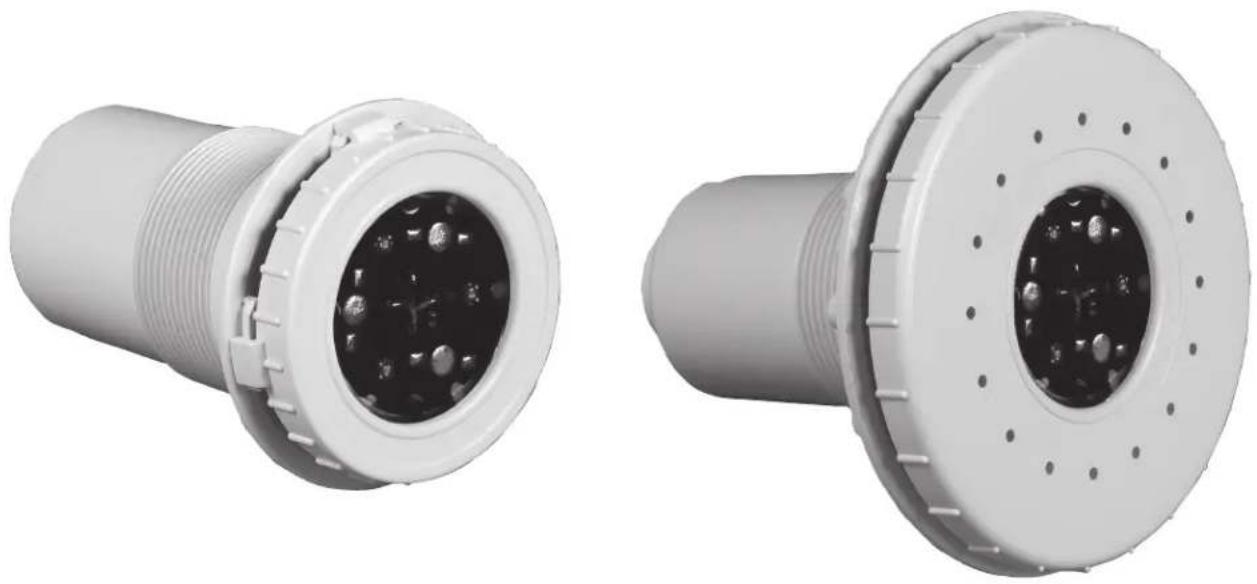
| Reference | 3429LEDBL | 3424LEDBL | 3429LEDRGB | 3424LEDRGB |
| Consumption in W | 5.5W | 8W | ||
| Power supply | 12 VAC | |||
| Number of LEDs | 18 | 9 | ||
| Lumens | 680 | 360 | ||
| Kelvin | 6500 | - | ||
| White / RGB | Cold white | RGB | ||
| Application | Liner | Concrete | Liner | Concrete |
| Trim colour | White | |||
| Plastic body | Niche + ABS Trim = Cofies | |||
| Radio frequency / Remote control by Radio frequency | No | |||
| Energy efficiency | This light is comprised of an ALP04-type light source with energy efficiency class (E)  ALP04 ALP04 | This RGB light fitting is not affected by standards EU2019/2015 and EU2019/2020 | ||
INSTALLATION
Technical Specifications
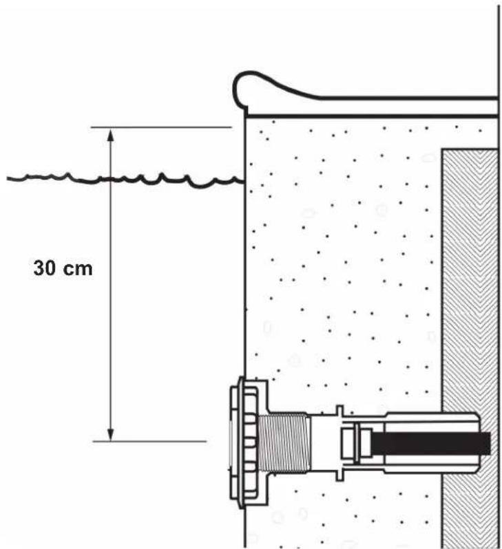
- The light should shine in the opposite direction to the house or terrace so as not to dazzle.
- The light should be placed at a maximum depth of 30 cm below the swimming pool stone crown the axis of the bulb.
- The hermetic tightness of the outlet and the sheath will be carried out according to good practice.
- This is a class III light, with a protection index of IP68, 1m. The bulb has a very low power voltage of 12 VAC for safety.
- During installation, provide sufficient cable length to be able to change the bulb out of the water.
Structure Built in the Liner
- Seal the light cable gland (ref. 3353) in the construction, in such a way that the front part is at the same level as the tiles or the lining.
- Screw the sheath into the light niche, making a hermetic seal.
- Screw the set into the cable gland, making another hermetic seal.
- Put the gasket on the front part of the light niche.
- Put the gasket on the flange of the light niche.
- Affix the hermetic sealing flange after putting the liner.
- Cut out the liner inside the niche.
- Thread the light optic cable through the sheath up to the junction box (ref. 3495EURO). Place the optic in front of the niche following back along the cable in the junction box, and fix the optic onto the plastic support.
- Pull and wind up the cable in the junction box and hermetically seal the junction box.
Liner panel structure:
• Make a 110 mm hole in the panel.
- Place the light niche inside the swimming pool. Tighten the nut behind (ref. 3492) to fasten it.
- The process of hermetically sealing the liner, the sheath cable and the placement of the light optic is the same as for the liner light.
Structure under construction without liner
- Seal the cable gland (ref. 3352) to the construction, in such a way that the front part is at the same level as the tiles or lining.
- Screw the light niche into the cable gland.
- The process of hermetically sealing the liner, the sheath cable and the placement of the light optic is the same as for the liner light.
| 1B P | RHX7010 2 RGB PRH | X20LDRV B | |
| 1 V P | RHX7009 2 White PRH | X20LDW |
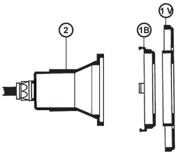
Junction box (Ref. 3495EURO) (not supplied)
- Connect the sheath of the light to the 3/4" outlet located at the base of the junction box, making another hermetic seal. - Use the connection blocks supplied with the junction boxes to connect the light to the power supply, twisting the cables and firmly tightening the screws of the connection terminals.
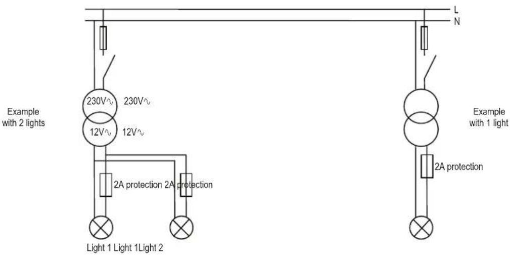
Transformer power
- A transformer with a secondary voltage of 12 V (12.5 V depending on the model) must be used. The power of the latter must be in line with the power of the light to be connected (minimum power = 9 VA for a white bulb and 13 VA for an RGB bulb).
• In all cases, the sum of the power of the lights must be less than or equal to the power of the transformer. - It is necessary to have independent protection for each light. It is necessary to ensure protection at the transformer output using 2 A fuses or circuit breakers (see the following diagram).
USE
Autonomous Mode (RGB colour light only)
In the absence of an RC box, the lights work autonomously and the user can choose between 18 modes: 11 fixed colours and 7 automatic colour change sequences (see the sequences box below).
| Sequence Colour/Program Sequence Colour/Program | |||
| 1 Colour: White 10 Colour: Green | |||
| 2 Colour: Blue 11* Colour: Emerald green | |||
| 3 Colour: Lagoon blue 12 Program: Quick colour alternation | |||
| 4 Colour: Cyan 13 Program: Slow colour alternation | |||
| 5 Colour: Purple 14 Program: 11 fixed colours | |||
| 6 Colour: Magenta 15 Program: Psychedelic | |||
| 7 Colour: Rose coloured | 16 Program: Blue/Cyan/White | ||
| 8 Colour: Red | 17 Program: Random colours 1 | ||
| 9 Colour: Orange | 18 Program: Random colours 2 | ||
| *: Possible customisable sequence using and connecting the control centre. | |||
Colour change can be obtained by cutting power to the lights for a very short time (<1s).
By successive interruptions, it is possible to scroll through the 18 operating modes. After mode 18, the lights return to the first automatic sequence (mode 1).
To synchronise the lights bringing them simultaneously to mode 2, it is advisable to cut the power for about 2s.
When the light is switched on after a stop of several seconds (>4s), it turns on in White for 15s, and then returns to the mode used the last time it was on; this allows for maximum lighting in case it accidentally falls into light-source support.
Safety (RGB colour light only)
In the event of an abnormal increase in temperature inside the bulb, a safety device prevents the bulb from lighting, and it emits red flashes. As soon as the temperature returns to normal, the bulb resumes normal operation.
If a voltage that is too low (<11V) or too high (>15V) is detected, the bulb will cease to function and will emit green flashes. To return to normal operation, it is essential to cut off the power to the lights.
MAINTENANCE
When replacing parts, always use original spares.
The bulb should be changed outside the water.
Changing of the light source contained in this light fitting should only be carried out by the manufacturer or its service agent, or an equivalently qualified person.
When changing the bulb and/or the cable, it is recommended to change all the parts that ensure the seals are watertight. When changing the bulb, the gasket and sealing elements must also be changed. Ensure they are correctly assembled.
In the event of malfunction, it will be necessary to change the entire LED bulb. Never open it or attempt to repair it.
To avoid accidents, if the power cable or cable sheath is damaged, it must be changed by the manufacturer, at an Authorised Service Centre or by a qualified technician.
The cable must meet the following mechanical and electrical requirements: H05RN-F with a minimum section of 2x1.5mm ^2 .
DISPOSAL OF BULBS AND REMOTE CONTROLS AT THE END OF THEIR USEFUL LIFE:

The symbol, a rubbish bin with a line below it, indicates the need for specific collection of electrical or electronic devices. This implies that these devices and their waste must not be disposed of together with household waste, but must be deposited at a specific collection point. If you require further information, contact your local town hall, or the distributor where you bought the product. The correct disposal of electrical and electronic devices helps prevent possible damage to the environment and human health, and helps preserve natural resources.
Brand : HAYWARD
Model : ColorLogic II
Category : Lighting