
W4YD - Screwdriver HiKOKI - Free user manual and instructions
Find the device manual for free W4YD HiKOKI in PDF.
| Brand | HiKOKI |
| Model | W4YD |
| Product type | Automatic screwdriver with strip feeder |
| Supply voltage | 230 V ~ / 240 V ~ (depending on region) |
| Power | 470 W |
| No-load speed | 4700 min⁻¹ |
| Screw capacity | Diameter: 4 mm, Length: 25 – 41 mm |
| Bit shank | 6.35 mm hex |
| Weight (without cord) | 1.7 kg (according to EPTA 01/2014) |
| Applications | Screw driving on plasterboard interior walls |
| Main functions | Automatic screwing with screw strip feeder; adjustment of screw depth and screw length |
| Included accessories | Screw feeder attachment, Phillips #2 bit, hook, strip, rubber cover, plastic case |
| Sound power level | 96 dB(A) |
| Sound pressure level | 85 dB(A) |
| Vibration emission | a_h < 2.5 m/s², K = 1.5 m/s² |
| Maintenance and cleaning | Clean with dry cloth or mild soapy water; check and replace carbon brushes; inspect bit |
| Safety | Wear safety glasses; disconnect before any adjustment; use only recommended bits |
| Spare parts and repairability | Replaceable carbon brushes; have maintenance performed by qualified repairer; use identical replacement parts |
| Warranty | Conforms to national regulations; does not cover normal wear and tear or misuse |
| General information | Manufacturer: HiKOKI, Parc de l'Eglantier, 22 rue des Cerisiers, Lisses-C.E. 1541, 91015 EVRY CEDEX, France |
Frequently Asked Questions - W4YD HiKOKI
User questions about W4YD HiKOKI
0 question about this device. Answer the ones you know or ask your own.
Ask a new question about this device
Download the instructions for your Screwdriver in PDF format for free! Find your manual W4YD - HiKOKI and take your electronic device back in hand. On this page are published all the documents necessary for the use of your device. W4YD by HiKOKI.
USER MANUAL W4YD HiKOKI
natural_image
Technical line drawing of a mechanical device with multiple pins and a handle (no text or symbols)Read through carefully and understand these instructions before use. Diese Anleitung vor Benutzung des Werkzeugs sorgfältig durchlesen und verstehen. Lire soigneusement et bien assimiler ces instructions avant usage. Prima dell'uso leggere attentamente e comprendere queste istruzioni. Deze gebruiksaanwijzing s.v.p. voor gebruik zorgvuldig doorlezen. Leer cuidadosamente y comprender estas instrucciones antes del uso. Antes de usar, leia com cuidado para assimilar estas instruções. Διαβάστε προσεκτικά και κατανοήσετε αυτές τις οδηγίες πριν τη χρήση.

Handling instructions Bedienungsanleitung Mode d'emploi Istruzioni per l'uso Gebruiksaanwijzing Instrucciones de manejo Instruções de uso Οδηγίες χειρισμού
1
2
3
4
5
6
7
8
natural_image
Line drawing of a hand holding a drill bit with chains attached (no text or symbols)9
10
11
natural_image
Line drawing of a hand holding a mechanical component, no text or symbols present12
13
natural_image
Cross-sectional diagram of a mechanical device with internal components and labeled part (25), no readable text or symbols present.14
15
16
17
18
| English Deutsch Français | |||
| 1 | Guide block Führungsblock Guide | ||
| 2 | Arrow mark Pfeilmarkierung Flèche | ||
| 3 | Lever Hebel Levier | ||
| 4 | Stopper Anschlag Cran d'arrêt | ||
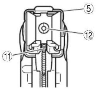
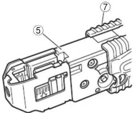
| 5 | Slider Schieber Glissière | ||
| 6 | The tip of a bit Bitspitze L'embout d'une pointe | ||
| 7 | Slider case Schiebergehäuse Boîtier coulissant | ||
| 8 | Depth adjuster knob | Einschraubtiefeneinstellknopf | Bouton de réglage de la profondeur |
| 9 | Belt guide | Gürtelführung | Guide du ruban |
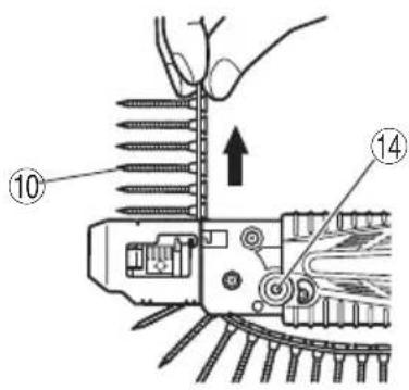
| 10 | Collated screw strips | Gürtelschrauben | Ruban de vis |
| 11 | Set on screw forward | Eine Schraube vorsetzen | Reglage d'une vis vers l'avant |
| 12 | Screw in position | Einschraubpositon | Vis en position |
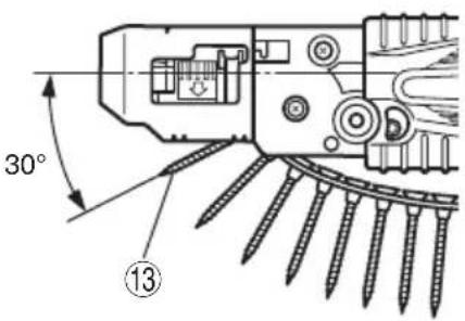
| 13 | 1 screw forward | 1 Schraube vorgesetzt | 1 vis vers l'avant |
| 14 | Release button | Freigabetaste | Touche de libération |
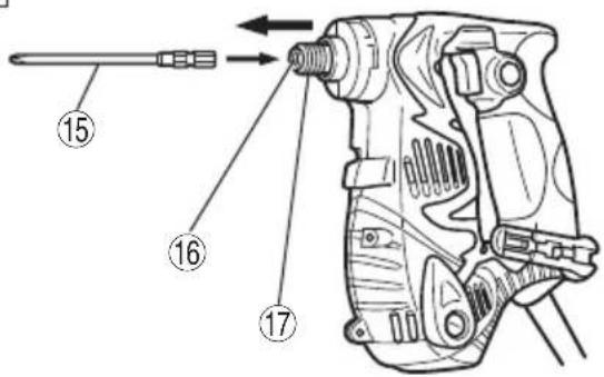
| 15 | Driver bit No.2 (136L) | Schraubenzieher Bit Nr.2 (136L) | Lame de tournevis No.2 (136L) |
| 16 | Socket hexagonal hole | Sechskantaufnahme | Orifice hexagonal de la douille |
| 17 | Guide sleeve | Fuhrungsbuchse | Manchon de guidage |
| 18 | Wall | Wand Mur | |
| 19 | Screw | Schraube | Vis |
| 20 | Guide to prevent damage to wall | Wandschutzführung | Guide pour éviter d'endommager le mur |
| 21 | 15 mm over | 15 mm Überstand | 15 mm au dessus |
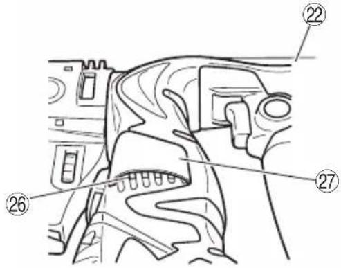
| 22 | Handle | Handgriff | Poignée |
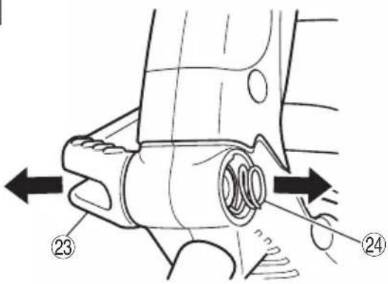
| 23 | Hook | Haken | Crochet |
| 24 | Spring | Feder Ressort | |
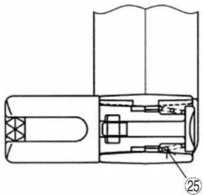
| 25 | Larger diameter faces away | Der große Durchmesser weist zur anderen Seite | Gros diamètre dirigé vers l'extérieur |
| 26 | Air vents | Ventilationsöffnungen | Event |
| 27 | Rubber cover | Gummiabdeckung | Couvercle en caoutchouc |
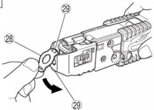
| 28 | Sheet Vorsatz | Feuillard | |
| 29 | Protrusion | Vorsprung | Protubérance |
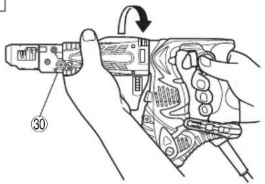
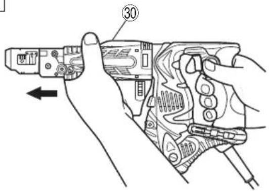
| 30 | Screw feed attachment | Schraubenzuführung | Accessoire d'alimentation de vis |
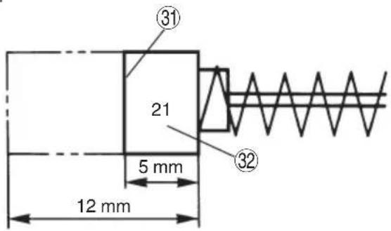
| 31 | Wear limit | Verschlei grenze | Límite d'usure |
| 32 | No. of carbon brush | Nr. der Kohlenbürste | No. de balai en carbone |
19
| Italiano Nederlands Español | |||
| 1 | Blocco guida Geleiderblok Fijación de la guía | ||
| 2 | Segno freccia Pijlmarkering Marca de fl echa | ||
| 3 | Leva Hendel Palanca | ||
| 4 | Fermo Schuifje Reten | ||
| 5 | Corsoio Schuifmechanisme Guía de deslizamiento | ||
| 6 | La punta di una lama Uiteinde van het schroefbit Punta del atornillador | ||
| 7 | Parte scorrevole Schuifmechanisme-huis Caja deslizable | ||
| 8 | Manopola di regolazione della profondità | Diepte-afstelknop | Perilla de la profundidad del atornillado |
| 9 | Guida per il nastro | Schroevenbandgeleidegroef | Guía de la correa |
| 10 | Nastro portaviti | Schroevenband | Tornillos de correa |
| 11 | Disporre una vite avanti | Zet 1 schroef vooruit | Coloque un tornillo hacia adelante |
| 12 | Vite in posizione Schroef staat | Tornillo en posicion | |
| 13 | 1 vite avanti | 1 schroef vooruit | 1 tornillo hacia adelante |
| 14 | Tasto di lasciare Ontgrendelknop | Botón de soltar | |
| 15 | Punta aviatatrice n.2 (136L) | Schroefblad nummer 2 (136L) | Broca de atornillador num.2 (136L) |
| 16 | Foro esagonale presa | Zeshoekige opening | Orificio hexagonal del portabrocas |
| 17 | Manicotto de guida Geleiderhuls Manguito guía | ||
| 18 | Parete | Muur | Pared |
| 19 | Vite | Schroef Tornillo | |
| 20 | Guida per prevenire danneggiamento al muro | Muur beveiligende geleider | Guía para evitar que se dañe la pared |
| 21 | oltre 15 mm | 15 mm te ver 15 mm por encima | |
| 22 | Impugnatura | Handgreep | Asidero |
| 23 | Gancio Ophanghaak | Gancho | |
| 24 | Molla | Veer | Resorte |
| 25 | Diametro più grande lontano da sé | De grotere diameter wijst van u vandaan | El diámetro más grande queda en dirección opuesta |
| 26 | Sfiatatoi | Luchtgaten | Conductos de aire |
| 27 | Coperchio di gomma Rubber afdekking Cubierta de caucho | ||
| 28 | Foglio | Plaatje | Placa |
| 29 | Parte sporgente | Uitsteeksel | Protuberancia |
| 30 | Dispositivo di avanzamento viti | Hulpstuk voor de aanvoer van schroeven | Dispositivo alimentador de tornillos |
| 31 | Limite di usura | Slijtagegrens Límite de desgaste | |
| 32 | N. della spazzola di carbone | Nr. van der koolborstel | No. de escobilla de carbon |
(Original instructions)
GENERAL POWER TOOL SAFETY WARNINGS
WARNING
Read all safety warnings, instructions, illustrations and specifications provided with this power tool.
Failure to follow all instructions listed below may result in electric shock, fire and/or serious injury.
Save all warnings and instructions for future reference.
The term "power tool" in the warnings refers to your mains-operated (corded) power tool or battery-operated (cordless) power tool.
1) Work area safety
a) Keep work area clean and well lit.
Cluttered or dark areas invite accidents.
b) Do not operate power tools in explosive atmospheres, such as in the presence of fl ammable liquids, gases or dust.
Power tools create sparks which may ignite the dust or fumes.
c) Keep children and bystanders away while operating a power tool.
Distractions can cause you to lose control.
2) Electrical safety
a) Power tool plugs must match the outlet. Never modify the plug in any way. Do not use any adapter plugs with earthed (grounded) power tools.
Unmodifi ed plugs and matching outlets will reduce risk of electric shock.
b) Avoid body contact with earthed or grounded surfaces, such as pipes, radiators, ranges and refrigerators.
There is an increased risk of electric shock if your body is earthed or grounded.
c) Do not expose power tools to rain or wet conditions.
Water entering a power tool will increase the risk of electric shock.
d) Do not abuse the cord. Never use the cord for carrying, pulling or unplugging the power tool.
Keep cord away from heat, oil, sharp edges or moving parts.
Damaged or entangled cords increase the risk of electric shock.
e) When operating a power tool outdoors, use an extension cord suitable for outdoor use.
Use of a cord suitable for outdoor use reduces the risk of electric shock.
f) If operating a power tool in a damp location is unavoidable, use a residual current device (RCD) protected supply.
Use of an RCD reduces the risk of electric shock.
3) Personal safety
a) Stay alert, watch what you are doing and use common sense when operating a power tool.
Do not use a power tool while you are tired or under the influence of drugs, alcohol or medication.
A moment of inattention while operating power tools may result in serious personal injury.
b) Use personal protective equipment. Always wear eye protection.
Protective equipment such as a dust mask, non-skid safety shoes, hard hat or hearing protection used for appropriate conditions will reduce personal injuries.
c) Prevent unintentional starting. Ensure the switch is in the off-position before connecting to power source and/or battery pack, picking up or carrying the tool.
Carrying power tools with your finger on the switch or energising power tools that have the switch on invites accidents.
d) Remove any adjusting key or wrench before turning the power tool on.
A wrench or a key left attached to a rotating part of the power tool may result in personal injury.
e) Do not overreach. Keep proper footing and balance at all times.
This enables better control of the power tool in unexpected situations.
f) Dress properly. Do not wear loose clothing or jewellery. Keep your hair and clothing away from moving parts.
Loose clothes, jewellery or long hair can be caught in moving parts.
g) If devices are provided for the connection of dust extraction and collection facilities, ensure these are connected and properly used.
Use of dust collection can reduce dust-related hazards.
h) Do not let familiarity gained from frequent use of tools allow you to become complacent and ignore tool safety principles.
A careless action can cause severe injury within a fraction of a second.
4) Power tool use and care
a) Do not force the power tool. Use the correct power tool for your application.
The correct power tool will do the job better and safer at the rate for which it was designed.
b) Do not use the power tool if the switch does not turn it on and off.
Any power tool that cannot be controlled with the switch is dangerous and must be repaired.
c) Disconnect the plug from the power source and/or remove the battery pack, if detachable, from the power tool before making any adjustments, changing accessories, or storing power tools.
Such preventive safety measures reduce the risk of starting the power tool accidentally.
d) Store idle power tools out of the reach of children and do not allow persons unfamiliar with the power tool or these instructions to operate the power tool.
Power tools are dangerous in the hands of untrained users.
e) Maintain power tools and accessories. Check for misalignment or binding of moving parts, breakage of parts and any other condition that may affect the power tool's operation. If damaged, have the power tool repaired before use.
Many accidents are caused by poorly maintained power tools.
f) Keep cutting tools sharp and clean.
Properly maintained cutting tools with sharp cutting edges are less likely to bind and are easier to control.
g) Use the power tool, accessories and tool bits etc. in accordance with these instructions, taking into account the working conditions and the work to be performed.
Use of the power tool for operations different from those intended could result in a hazardous situation.
h) Keep handles and grasping surfaces dry, clean and free from oil and grease.
Slippery handles and grasping surfaces do not allow for safe handling and control of the tool in unexpected situations.
5) Service
a) Have your power tool serviced by a qualified repair person using only identical replacement parts.
This will ensure that the safety of the power tool is maintained.
PRECAUTION
Keep children and infi rm persons away.
When not in use, tools should be stored out of reach of children and infi rm persons.
PRECAUTIONS ON USING AUTOMATIC SCREWDRIVER
- This automatic screwdriver is designed for tightening and loosening screws. Use it only for these operation.
-
One-hand operation is extremely dangerous; hold the unit firmly with both hands when operating.
-
Use original bits specifically for the automatic screwdriver. Use no bits other than the original bits specifically for the automatic screwdriver. Use of any other bit can result in screws sticking out and screw feed malfunctioning.
- After installing the driver bit, pull lightly out the bit to make sure that it does not come loose. If the bit is not installed properly, it can come loose during use, which can be dangerous.
- Screw in screws with the main unit held straight.
If the driver is slanted relative to the screw, the screw head can be damaged and the bit worn. Moreover, the prescribed torque is not transmitted to the screw, resulting in screws left sticking out. Place the drive straight against the screw and screw in.
- Use the prescribed screws.
Do not use any other screws. They can cause abnormal work (screws fallen over or sticking out) and break downs (screw jamming and bit wear).
- Protect your eyes with protective glasses.
Always wear protective glasses while working. Drilling scatters plaster powder and tape dust, which are dangerous if they get into your eyes. - Watch out for wires and pipes in walls and ceilings.
When working on floors, walls, or ceilings, check f wires and pipes ahead of time. Work carefully to avoid shocks and explosions. - When the screw feed attachment is removed, always use the correct driver bit for the screw size.
- When the screw feed attachment is removed, if the screwdriver is positioned at an angle against the tightening screw, the head of the screw may be damaged or the fixed tightening force will not transfer to the screw. Always position the tightening screw and the screwdriver at a straight angle and then tighten the screw.
SPECIFICATIONS
| Voltage (by areas)* (230 V, 240 V) | ~ | |
| Power input | 470 W | |
| No-load speed | 4700 min-1 | |
| Capacity | Screw size | 4 mm |
| Screw length | 25 – 41 mm | |
| Bit shank size | 6.35 mm Hex. | |
| Weight (without cord)** | 1.7 kg | |
* Be sure to check the nameplate on product as it is subject to change by areas.
** According to EPTA-Procedure 01/2014
STANDARD ACCESSORIES
(1) Screw feed attachment.... 1
(Assembled in main body)
(2) No. 2 Plus Bit....1
(Assembled in main body)
(3) Hook....1
(4) Sheet....2
(5) Rubber cover....1
(6) Plastic case ....1
Standard accessories are subject to change without notice.
APPLICATIONS
○ Screw driving into indoor gypsum board.
PRIOR TO OPERATION
- Power source
Ensure that the power source to be utilized conforms to the power requirements specified on the product nameplate.
- Power switch
Ensure that the power switch is in the OFF position. If the plug is connected to a receptacle while the power switch is in the ON position, the power tool will start operation immediately, which could cause a serious accident.
3. Extension cord
When the work area is removed from the power source, use an extension cord of sufficient thickness and rated capacity. The extension cord should be kept as short as practicable.
4. Preparing and checking the work environment
Make sure that the work site meets all the conditions laid forth in the precautions.
5. Preparing the screws
Select screws appropriate to the application.
6. Bit checking and replacement
A No. 2 Plus bit is installed on this machine as a standard accessory. Always inspect the bit to make sure it is not damaged. Using worn bits can cause screw-in malfunctions. Inspect the bit before work and quickly replace it with a new one when it starts to wear out. When the bit must be replaced due to bit damage or any other reason, replace it according to the instructions in Bit installation and removal.
ADJUSTING THE SCREW LENGTH AND SCREW-IN DEPTH
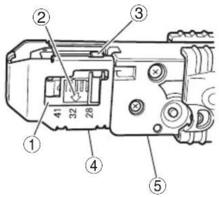
1. Set the screw length (Fig. 1)
Set the screw length on this unit by sliding the guide block.
(1) Slide the guide block while holding down the lever and align the arrow on the guide block with the number on the stopper to match the screw length.
(2) Find the screw length and screw guide position by checking the table below.
| STOPPER NUMBER SCREW LENGTH | |
| 28 25 – 28 mm | |
| 32 32 – 35 mm | |
| 41 38 – 41 mm | |
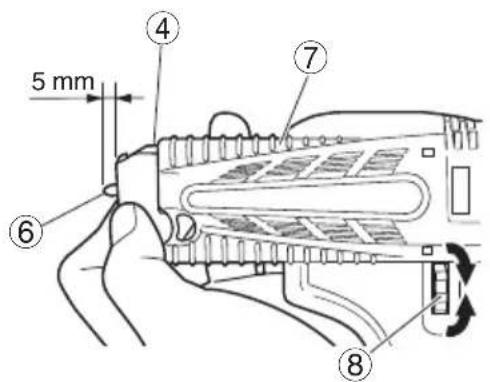
2. Adjust the screw-in depth (Fig. 2)
Adjust the screw-in depth on this unit by turning the depth adjuster knob.
(1) Press the slider all the way in to the slider case. Then rotate the depth adjuster knob so that the bit tip protrudes about 5 mm.
(2) Try driving a screw and make fi ne adjustments as needed. To make the fi ne adjustment, rotate towards A (counterclockwise) if the screw head is too high after screw-in. If the screw head is too low after screw-in, then rotate towards B (clockwise).
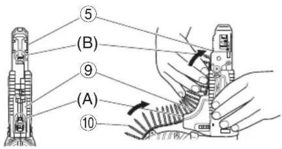
INSTALLING AND REMOVING THE SCREW STRIP
1. Install (Fig. 3)
(1) Insert the tip of the linked screw strip into the belt guide groove (A section).
(2) Insert the tip of the tape into the slider groove (B section) and press inwards in the arrow direction.
(3) Set so the screw on the strip is just prior (1 screw width) to the screw-in position (Fig. 4, Fig. 5).
CAUTION
○ Set the screw strip securely inside. If not set securely, the bit might scratch the board surface (low feed pressure) or the screw might be wasted (too much feed pressure).
2. Removal (Fig. 6)
(1) If you run out of screws on the tape or want to remove a screw strip during a job, pull in the direction of the arrow as shown in the figure to remove.
(2) You can return the screw strip in the opposite direction by pressing the reverse button.
INSTALLING AND REMOVING THE BIT
CAUTION
To prevent the chance of an accident, always turn off the power switch and pull out the plug from the socket.
NOTE
- When replacing the bit be sure to install it securely so it will not come loose or fall out later.
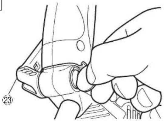
1. Removing the screw strip attachment
Grip the unit securely with one hand. With your other hand, rotate the screw strip attachment in the direction of the arrow in Fig. 17. Next pull in the direction of the arrow in Fig. 18 and remove.
NOTE
This will be hard to remove if the lath or plaster powder attaches near the attachment slot. Clean this section carefully to prevent the lath or plaster powder from adhering here.
2. Attaching and removing the bit (Fig. 7)
No bits other than plus driver (Phillips) bits (No. 2, 136 mm long) can be used for screw strip tightening jobs. Attach the bits securely using the following procedure.
Move the guide sleeve to the top edge, feed the bit into hexagonal hole on the anvil and then release the guide sleeve.
To remove, perform the above procedure in reverse order.
NOTE
☐ The bit was not installed correctly (securely) if the guide sleeve will not return to its original position. Keep inserting the bit inside the hexagonal socket head hole until it makes contact.
3. Installing the screw strip attachment
Install using the steps in "1. Removing the screw strip attachment" in reverse order.
HOW TO USE
CAUTION
Always use safety goggles during the work.
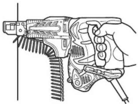
1. How to operate
Press the unit straight up against the work and pull the switch trigger to automatically feed and tighten the screws (Fig. 8).
NOTE
- Place this unit straight up against the work during screw-tightening. Using the unit while at an angle to the work might damage the screw head or cause bit wear. Also the proper tightening torque will not be transmitted to the screw and might cause the screw to seat improperly.
○ Press firmly on the unit until the screw tightening is complete. Loosening the pushing pressure on the unit might cause the screw to seat improperly.
○ When driving the screw, avoid hitting the unit as pushing in.
This could prevent the screw from being sent normally.
☐ Attempting to tighten one screw on top of another will cause the screw to fall or stop the screw feed so use caution.
○ Driving blanks
During continuous screw tightening, you might not notice you have run out of screws and continue to operate the unit. Driving without any screws will cause the bit to damage the lath or plaster board, so do the screw tightening while checking the number of screws remaining.
○ If the slider does not move smoothly, try cleaning the sliding surfaces with an air gun, etc.
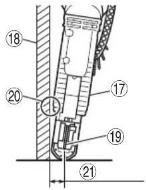
2. Using in corners (Fig. 9)
Unit can drive screws at positions as close as 15 mm from the wall.
NOTE
○ Do not attempt to drive screws when closer to the wall than 15 mm.
Do not drive screws while the slider case is in contact with the wall. Damaging the screw head causes bit wear. The proper tightening torque is not transmitted to the screw if the screw head or bit is worn. This might also cause the screw not to seat properly and might cause this unit to break.
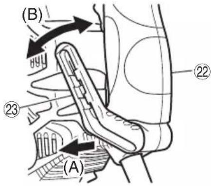
3. Using the hook
The hook can be installed on the right or left side and the angle can be adjusted in 5 steps between 0° and 80°.
(1) Operating the hook
(a) Pull out the hook toward you in the direction of arrow (A) and turn in the direction of arrow (B) (Fig. 10).
(b) The angle can be adjusted in 5 steps ( 0^ , 20^ , 40^ , 60^ , 80^ ).
Adjust the angle of the hook to the desired position for use.
(2) Switching the hook position
CAUTION
Incomplete installation of the hook may result in bodily injury when used.
(a) Securely hold the main unit and remove the screw using a slotted head screwdriver or a coin (Fig. 11).
(b) Remove the hook and spring (Fig. 12).
(c) Install the hook and spring on the other side and securely fasten with screw (Fig. 13).
NOTE
Pay attention to the spring orientation. Install the spring with larger diameter away from you (Fig. 13).
4. Attaching the rubber cover (Fig. 14)
If concerned about wind coming in from the air vents, install the accessory rubber cover over the holes to change the direction of air flow.
To install the cover, press the protrusions firmly into the air vents. To install easily, press inwards, in order from the sides.
5. When the slider won't move smoothly
If the slider will not move smoothly, try cleaning the sliding surfaces of the slider and slider case with an air gun, etc. (Fig. 15).
NOTE
The unit tends to easily become covered with lath or plaster board dust during jobs where it faces upwards. Clean the sliding surfaces at regular periods during the work task.
6. Attaching the sheet
If the sheet has been damaged and cannot be used, please replace the sheet with attached one. Attach the sheet by inserting the holes on the sheet on the two protrusions on the stopper (Fig. 16).
SCREW HANDLING
NOTE
Handle both the packed box of screws and the collated screw strips with care. If you drop them, screws can come out of the collated tape and cause screw feed malfunctions. Do not expose the screws to prolonged periods of direct sunlight or outside air. They can cause rust and collated tape problems, so when you will not be using the screws for awhile, put them in the screw packing box or the like.
MAINTENANCE AND INSPECTION
1. Inspecting the driver bit
Using a broken bit or one with a worn out tip is dangerous because the bit can slip. Replace it by a new one.
2. Inspecting the mounting screws
Regularly inspect all mounting screws and ensure that they are properly tightened. Should any of the screws be loose, retighten them immediately. Failure to do so may result in serious hazard.
3. Inspecting the carbon brushes (Fig. 19)
The motor employs carbon brushes which are consumable parts.
Since an excessively worn carbon brush can result in motor trouble, replace the carbon brush with a new one having the same carbon brush No. shown in the figure, when it becomes worn to or near the “wear limit”. In addition, always keep carbon brushes clean and ensure that they slide freely within the brush holders.
4. Replacing carbon brushes
Disassemble the brush caps with a slotted-head screwdriver. The carbon brushes can then be easily removed.
5. Maintenance of the motor
The motor unit winding is the very "heart" of the power tool. Exercise due care to ensure the winding does not become damaged and/or wet with oil or water.
6. Cleaning of the outside
When the automatic screwdriver is stained, wipe with a soft dry cloth or a cloth moistened with soapy water. Do not use chloric solvents, gasoline or paint thinner, as they melt plastics.
CAUTION
In the operation and maintenance of power tools, the safety regulations and standards prescribed in each country must be observed.
GUARANTEE
We guarantee HiKOKI Power Tools in accordance with statutory/country specific regulation. This guarantee does not cover defects or damage due to misuse, abuse, or normal wear and tear. In case of complaint, please send the Power Tool, undismantled, with the GUARANTEE CERTIFICATE found at the end of this Handling instruction, to a HiKOKI Authorized Service Center.
NOTE
Due to HiKOKI's continuing program of research and development, the specifications herein are subject to change without prior notice.
IMPORTANT
Correct connection of the plug
The wires of the mains lead are coloured in accordance with the following code:
Blue: - Neutral
Brown: - Live
As the colours of the wires in the mains lead of this tool may not correspond with the coloured markings identifying the terminals in your plug proceed as follows:
The wire coloured blue must be connected to the terminal marked with the letter N or coloured black.
The wire coloured brown must be connected to the terminal marked with the letter L or coloured red.
Neither core must be connected to the earth terminal.
NOTE
This requirement is provided according to BRITISH STANDARD 2769: 1984.
Therefore, the letter code and colour code may not be applicable to other markets except United Kingdom.
Information concerning airborne noise and vibration
The measured values were determined according to EN62841 and declared in accordance with ISO 4871.
Measured A-weighted sound power level: 96 dB (A)
Measured A-weighted sound pressure level: 85 dB (A)
Uncertainty KpA: 3 dB (A).
Wear hearing protection.
Vibration total values (triax vector sum) determined according to EN62841.
Screwdriving without impact:
Vibration emission value a_h < 2.5 m/s^2
Uncertainty K = 1.5 m/s ^4
The declared vibration total value has been measured in accordance with a standard test method and may be used for comparing one tool with another.
It may also be used in a preliminary assessment of exposure.
WARNING
☐ The vibration emission during actual use of the power tool can differ from the declared total value depending in the ways in which the tool is used.
- Identify safety measures to protect the operator that are based on an estimation of exposure in the actual conditions of use (taking account of all parts of the operating cycle such as the times when the tool is switched off and when it is running idle in addition to the trigger time).
Visser sans percussion :
natural_image
Line drawing of a quill pen with inkwell (no text or symbols)| English Nederlands | ||
| GUARANTEE CERTIFICATE1 Model No.2 Serial No.3 Date of Purchase4 Customer Name and Address5 Dealer Name and Address(Please stamp dealer name and address) | GARANTIEBEWIJS1 Modelnummer2 Serienummer3 Datum van aankoop4 Naam en adres van de gebruiker5 Naam en adres van de handelaar(Stempel a.u.b. naam en adres vande de handelaar) | |
| Deutsch Español | ||
| GARANTIESCHEIN1 Modell-Nr.2 Serien-Nr.3 Kaufdatum4 Name und Anschrift des Kunden5 Name und Anschrift des Händlers(Bitte mit Namen und Anschrift des Handlers abstempeln) | CERTIFICADO DE GARANTÍA1 Número de modelo2 Número de serie3 Fecha de adquisición4 Nombre y dirección del cliente5 Nombre y dirección del distribuidor(Se ruega poner el sello del distribuidor con su nombre y dirección) | |
| Français Português | ||
| CERTIFICAT DE GARANTIE1 No. de modèle2 No de série3 Date d'achat4 Nom et adresse du client5 Nom et adresse du revendeur(Cachet portant le nom et l'adresse du revendeur) | CERTIFICADO DE GARANTIA1 Número do modelo2 Número do série3 Data de compra4 Nome e morada do cliente5 Nome e morada do distribuidor(Por favor, carimbe o nome e morada do distribuidor) | |
| Italiano Ελληνικά | ||
| CERTIFICATO DI GARANZIA1 Modello2 N° di serie3 Data di acquisto4 Nome e indirizzo dell'acquirente5 Nome e indirizzo del rivenditore(Si prega di apporre il timbro con questi dati) | ΠΙΣΤΟΠΟΙΗΤΙΚΟ ΕΓΓΥΗΣΗΣ1 Αρ. Μοντέλου2 Αύξων Αρ.3 Ημερομηνία αγοράς4 Όνομα και διεύθυνση πελάτη5 Όνομα και διεύθυνση μεταπωλητή(Παρακαλούμε να χρησιμοποιηθεί σφραγίδα) | |
HiKOKI
| 1 | |
| 2 | |
| 3 | |
| 4 | |
| 5 |
Siemensring 34, 47877 willich, Germany
Tel: +49 2154 49930
Fax: +49 2154 499350
URL: http://www.hikoki-powertools.de
Hikoki Power Tools Netherlands B.V.
Brabanthaven 11, 3433 PJ Nieuwegein, The Netherlands
Tel: +31 30 6084040
Fax: +31 30 6067266
URL: http://www.hikoki-powertools.nl
Hikoki Power Tools (U.K.) Ltd.
Precedent Drive, Rooksley, Milton Keynes, MK 13, 8PJ,
United Kingdom
Tel: +44 1908 660663
Fax: +44 1908 606642
URL: http://www.hikoki-powertools.uk
Hikoki Power Tools France S.A.S.
Hikoki Power Tools Belgium N.V./S.A.
Koningin Astridlaan 51, B-1780 Wemmel, Belgium
Tel: +32 2 460 1720
Fax: +32 2 460 2542
URL http://www.hikoki-powertools.be
Hikoki Power Tools Italia S.p.A
Via Piave 35, 36077, Altavilla Vicentina (VI), Italy
Tel: +39 0444 548111
Fax: +39 0444 548110
URL: http://www.hikoki-powertools.it
Hikoki Power Tools Ibérica, S.A.
C/ Puigbarral, 26-28, Pol. Ind. Can Petit, 08227 Terrassa
(Barcelona), Spain
Tel: +34 93 735 6722
Fax: +34 93 735 7442
URL: http://www.hikoki-powertools.es
natural_image
Line drawing of a quill pen with inkwell (no text or symbols)
natural_image
Line drawing of a quill pen with inkwell (no text or symbols)| English Nederlands | ||
| EC DECLARATION OF CONFORMITYWe declare under our sole responsibility that Automatic Screwdriver, identified by type and specific identification code *1), is in conformity with all relevant requirements of the directives *2) and standards *3). Technical fi le at *4) – See below.The European Standard Manager at the representative office in Europe is authorized to compile the technical fi le.The declaration is applicable to the product affi xed CE marking. | EC VERKLARING VAN CONFORMITEITWij verklaren onder onze eigen verantwoordelijkheid dat Schroef automaat, geïdentificeerd door het type en de specifieke identificatiecode *1), voldoet aan alle relevante bepalingen van de richtlijnen *2) en normen *3). Technische documentatie bij*4) – zie onder.De Europese Normen Manager bij de vertegenwoordiging in Europa is gemachtigd om het technisch dossier samen te stellen.Deze verklaring is van toepassing op producten voorzien van de CE-markeringen. | |
| Deutsch Español | ||
| EG-KONFORMITÄTSERKLÄRUNGWir erklären in alleiniger Verantwortung, dass der durch den Typ und den spezifischen Identifizierungscode *1) identifizierte Automatische Magazinschrauber allen einschlägigen Bestimmungen der Richtlinien *2) und Normen *3) entspricht. Technische Unterlagen unter *4) – Siehe unten.Die Leitung der repräsentativen Behörde für europäische Normen und Richtlinien ist berechtigt, die technischen Unterlagen zusammenzustellen.Die Erklärung gilt für die an dem Produkt angebrachte CE-Kennzeichnung. | DECLARACIÓN DE CONFORMIDAD DE LA CEDeclaramos bajo nuestra única responsabilidad que el Atomillador automático, identificado por tipo y por código de identificación específico *1), está en conformidad con todas las disposiciones correspondientes de las directivas *2) y de las normas *3). Documentación técnica en *4) – Ver a continuación.El Director de Normas Europeas en la oficina de representación en Europa está autorizado para elaborar el expediente técnico.La declaración se aplica al producto con marcas de la CE. | |
| Français Português | ||
| DECLARATION DE CONFORMITE CENous déclarons sous notre entière responsabilité que la Visseuse à distributeur automatique, identifiée par le type et le code d'identification spécifique *1) est en conformité avec toutes les exigences applicables des directives *2) et des normes *3). Dossier technique en *4) - Voir ci-dessous.Le Gestionnaire des normes européennes du bureau de représentation en Europe est autorisé à constituer le dossier technique.Cette déclaration s'applique aux produits désignés CE. | DECLARAÇÃO DE CONFORMIDADE CEDeclaramos, sob nossa única e inteira responsabilidade, que a Aparafusadora automática, identificada por tipo e código de identificação específico *1), está em conformidade com todos os requisitos relevantes das diretivas *2) e normas *3). Ficheiro técnico em *4)–Consulte abaixo.O Gestor de Normas Europeas no escritório de representação na Europa está autorizado a compilar o fi cheiro técnico.A declaração aplica-se aos produtos com marca CE. | |
| Italiano Ελληνικά | ||
| DICHIARAZIONE DI CONFORMITÀ CEDichiariamo sotto la nostra esclusiva responsabilità che l'Avvitatore automatico a nastro, identificato dal tipo e dal codice identificativo specifico *1), è conforme a tutti i requisiti pertinenti delle direttive *2) e degli standard *3). Documentazione tecnica presso *4) – Vedere sotto.Il gestore delle norme europee presso l'ufficio di rappresentanza in Europa è autorizzato a compilare il fascicolo tecnico.La dichiarazione è applicabile ai prodotti cui sono applicati i marchi CE. | ΕΚ ΔΗΛΟΣΗ ΕΝΑΡΜΟΝΙΣΜΟΥΔηλώνουμε με αποκλειστική μας ευθύνη ότι το Αυτοτροφοδοτούμενο καταβίδι, το οποίο προσδιορίζεται από τον τύπο και ειδικό αναγνωριστικό κωδικό *1), είναι σύμφωνο με όλες τις σχετικές απαιτήσεις των Οδηγιών *2) καιμε τα σχετικά πρότυπα *3). Τεχνικό Αρχείο στο *4) – Δείτε παρακάτω.Ο Διαχειριστης Ευρωπαϊκών Προτύπων στο γραφείο εκπροσώπησης στην Ευρώπη είναι εξουσιοδοτημένος για τη σύνταξη του τεχνικού φακέλου.Η δήλωση ισχύει μόνο για το προϊόν που είναι τοποθετημένη σήμανση CE. | |
| *1) W4YD C330149R*2) 2006/42/EC, 2014/30/EU, 2011/65/EU*3) EN62841-1:2014EN62841-2-2:2015EN55014-1:2006+A1:2009+A2:2011EN55014-2:1997+A1:2001+A2:2008EN61000-3-2:2014EN61000-3-3:2013 | ||
| *4) Representative office in EuropeHikoki Power Tools Deutschland GmbHSiemensring 34, 47877 Willich, GermanyHead office in JapanKoki Holdings Co., Ltd.Shinagawa Intercity Tower A, 15-1, Konan 2-chome,Minato-ku, Tokyo, Japan | 31. 5. 2019Naoto YamashiroEuropean Standard Manager31. 5. 2019A. NakagawaCorporate Officer | |


- (Original instructions)
- GENERAL POWER TOOL SAFETY WARNINGS
- WARNING
- PRECAUTION
- PRECAUTIONS ON USING AUTOMATIC SCREWDRIVER
- STANDARD ACCESSORIES
- APPLICATIONS
- PRIOR TO OPERATION
- Extension cord
- Preparing and checking the work environment
- Preparing the screws
- Bit checking and replacement
- ADJUSTING THE SCREW LENGTH AND SCREW-IN DEPTH
- Set the screw length (Fig. 1)
- Adjust the screw-in depth (Fig. 2)
- INSTALLING AND REMOVING THE SCREW STRIP
- Install (Fig. 3)
- CAUTION
- Removal (Fig. 6)
- INSTALLING AND REMOVING THE BIT
- NOTE
- Removing the screw strip attachment
- Attaching and removing the bit (Fig. 7)
- Installing the screw strip attachment
- HOW TO USE
- How to operate
- Using in corners (Fig. 9)
- Using the hook
- Attaching the rubber cover (Fig. 14)
- When the slider won't move smoothly
- Attaching the sheet
- SCREW HANDLING
- MAINTENANCE AND INSPECTION
- Inspecting the driver bit
- Inspecting the mounting screws
- Inspecting the carbon brushes (Fig. 19)
- Replacing carbon brushes
- Maintenance of the motor
- Cleaning of the outside
- GUARANTEE
- IMPORTANT
- Correct connection of the plug
- Information concerning airborne noise and vibration
- Hikoki Power Tools Netherlands B.V.
- Hikoki Power Tools (U.K.) Ltd.
- Hikoki Power Tools France S.A.S.
- Hikoki Power Tools Belgium N.V./S.A.
- Hikoki Power Tools Italia S.p.A
- Hikoki Power Tools Ibérica, S.A.
Brand : HiKOKI
Model : W4YD
Category : Screwdriver