TQ18B - Speaker Turbosound - Free user manual and instructions
Find the device manual for free TQ18B Turbosound in PDF.
| Product type | Passive subwoofer |
| Brand | Turbosound |
| Model | TQ18B |
| Transducer | 18 inches |
| Connectors | Neutrik Speakon NL4 (input and link) |
| Impedance | 8 ohms (estimated) |
| Recommended amplification | Lab Gruppen PLM+ (PLM8k44, PLM12k44, PLM20k44) or D series |
| Required presets | Official Lake presets (download from turbosound.com or labgruppen.com) |
| DSP compatibility | Exclusively Lake Controller / Lab Gruppen |
| Mounting | M10 suspension points, 35 mm pole mount socket, ground feet, optional casters |
| Logo rotation | Yes, manual |
| Application | Touring and fixed installations |
| Simulation software | EASE Focus 3 |
| Secondary safety system | Mandatory when suspended (independent steel cable or chain) |
| Maintenance | Clean with a dry cloth, regularly check attachment points |
| Approximate weight | 45 kg (estimated) |
| Dimensions (W x H x D) approximate | 560 x 600 x 700 mm (estimated) |
Frequently Asked Questions - TQ18B Turbosound
User questions about TQ18B Turbosound
0 question about this device. Answer the ones you know or ask your own.
Ask a new question about this device
Download the instructions for your Speaker in PDF format for free! Find your manual TQ18B - Turbosound and take your electronic device back in hand. On this page are published all the documents necessary for the use of your device. TQ18B by Turbosound.
USER MANUAL TQ18B Turbosound
natural_image
Two black industrial storage cabinets with open doors and internal compartments, shown from different angles (no text or symbols visible)TQ Series
TQ18B
Single 18" Reflex Loaded Subwoofer for Touring and Installation Applications
TQ15B
Single 15" Reflex Loaded Subwoofer for Touring and Installation Applications
2 TQ15B and TQ16B Quick Stat. Guide 3
EN
Safety Instruction
-
Read these instructions.
-
Keep these instructions.
-
Hood all warnings.
-
Followal instructions.
-
Do not use this apparatus near water.
-
Clean only with dry cloth
-
Do not block any ventilation openings, install in
accordance with the manufacturer's Instructio
- Do not install near any heat sources such
including Washington that provides best
- The only attachments accessories spaced
by the manufacturer.
ES

10. Use only with
the cart, stand, tripod,
bracket, or table specified
by the author of H.
DE
(019)
the cart/ap
Contrainment of the injury from my liver.

11. Correct disposal of this
product: this symbol indicates that
this product must not be disposed
2020年1月1日
(2019)5III and your national
law. This product should be taken
to a collection center licensed for
the recycling of waste electrical and electronic equipment (EEE). The mishandling of this type of waste could have a possible negative impact on the environment and human health due to potentially hazardous substances that are generally associated with EEE. At the same time, your cooperation in the correct disposal of this product will contribute to the efficient use of natural resources. For more information about where you can take your waste equipment for recycling, please contact your local city office, or your household waste collection service.
- Do not install in a confined space, such as a
book case or similar unit.
- Do not place naked flame sources, such as lighted
candles, on the apparatus.
A. Sina todas as instructes
4) Appresentable to be seen
m = 311
PT
IT
4 TQ158 and TQ188 Quick Span Guide 5
(H) Belangrijke
unstatement in combination
is antecapten of die in
combinatie met het
uvaapion 30 product m
(3) 10.10.12.14: 15:30, 16:30, 17:30, 18:30, 19:30, 20:30, 21:30, 22:30, 23:30, 24:30, 25:30, 26:30, 27:30, 28:30, 29:30, 30:30, 31:30, 32:30, 33:30, 34:30, 35:30, 36:30, 37:30, 38:30, 39:30, 40:30, 41:30, 42:30, 43:30, 44:30, 45:30, 46:30, 47:30, 48:30, 49:30, 50:30, 51:30, 52:30, 53:30, 54:30, 55:30, 56:30, 57:30, 58:30, 59:30, 60:30, 61:30, 62:30, 63:30, 64:30, 65:30, 66:30, 67:30, 68:30, 69:30, 70:30, 71:30, 72:30, 73:30, 74:30, 75:30, 76:30, 77:30, 78:30, 79:30, 80:30, 81:30, 82:30, 83:30, 84:30, 85:30, 86:30, 87:30, 88:30, 89:30, 90:30, 91:30, 92:30, 93:30, 94:30, 95:30, 96:30, 97:30, 98:30, 99:30, 100:30
for art. Bishinda checkstall
genom stubbling.

Contact common, showing pertaining else
In Malaria, a healthy control group information of the species' disease in Japan.
-
Let the world's best
-
Inmania, the left arm of my own
1.29. Ten Sustijas che in a line of
1.2.3. (in %) of the
Thank you for choosing a Turbosound loudspeaker product for your application. If you would like further information about this or any other product, please visit our website at turbosound.com.
Unpacking the Loudspeaker
After unpacking the unit, please check carefully for damage. If damage is found, please notify your supplier at once. You, the consignee, must instigate any claim. Please retain all packaging in case of future return shipment.
About this Quick Start Guide
This QSG describes details of the TQ15B and TQ18B subwoofers. These instructions shall only be used with these components. Possession of these instructions and procedures does not imply authorisation for their use.
General Safety
The operation of your product as part of a suspended system, if installed incorrectly and improperly, can potentially expose persons to serious health risks and even death. In addition, please ensure that electrical, mechanical and acoustic considerations are discussed with qualified and certified (by local, state or national authorities) personnel prior to any installation.
Installation and setup should only be carried out by qualified and authorised personnel observing the valid local, state and other safety regulations applicable in your country. If any parts or components are missing please contact your dealer before attempting to set up the system.
It is the responsibility of the person installing the assembly to ensure that the suspension/ficking points are suitable for the intended use.
We also recommend you schedule Turbosound training with our sales partners and applications team.
Equipment used to connect to the Turbosound rigging system must be properly rated and must conform to the local, state and other safety regulations. Do not use Turbosound rigging with other types or brands of loudspeakers. This practice may compromise safety standards and Music Tribe Global Brands Ltd will not be responsible for damage or injury so caused. Do not modify the accessories, or use them in a way other than that described in this QSG. Rigging components supplied as part of a complete assembly are non-interchangeable and must not be exchanged with the component parts of any other assembly.
Welding, or any other means of permanently fixing rigging components to each other or to cabinet fixing points is not allowed. Rigging components or assemblies must only be fixed to Turbosound loudspeaker cabinets using the cabinet fixing points.
Music Tribe Global Brands Ltd assumes no liability for any damage or personal injury resulting from improper use, installation or operation of the product. Regular checks must be conducted by qualified personnel to ensure that the system remains in a secure and stable condition. Make sure that, where the product is suspended, the area underneath the product is free of human traffic. Do not suspend the product in areas which can be entered or used by members of the public.
Always refer to EASE Focus 3 modeling software error and warning indications prior to installation.
Secondary Safeties
All loudspeakers flown in theatres, studios or other places of work and entertainment shall, in addition to the principle load bearing means of suspension, be provided with an independent, properly rated, and securely attached secondary safety. Only steel wire ropes or steel chains of an approved construction and load rating shall be used as secondary safeties. Plastic-covered steel wire ropes are not permitted for use as secondary safeties.
The secondary safety suspension must be independent of the primary suspension points and capable of carrying the total system weight. The additional safety device must be mounted in a way that the loudspeaker is caught by the safety device without any drop and swing, in the event that the primary suspension fails.
Operational Safety
The procedures require the use of two or more authorised persons.
Produce a lift plan: before any lift takes place, you must formulate a lift plan that describes the exact steps and procedures that will be carried out.
The plan must be shared with all assistants and stake-holders in the lift so that each person will understand their responsibilities.
Observe all instructions given on the respective instruction labels of the rigging components and loudspeakers.
When using chain hoists, make sure nobody is directly underneath or in the vicinity of the loudspeakers.
During assembly pay attention to the possible risk of crushing.
Wear suitable protective clothing.
Safety Inspections
Carefully inspect rigging system components and cabinets for defects or signs of damage before proceeding to assemble the speaker to be flown. If any parts are damaged or suspect, or if there is any doubt as to the proper functioning and safety of the items DO NOT USE THEM and withdraw them from use immediately.
System Requirements
TQ15B and TQ18B subwoofers operate as a passive system and require only one amplifier channel and DSP for normal forward firing operation; Cardiolid bass set ups will require additional amplifier and DSP channels.
All TO series loudspeakers exclusively use Lake pre-sets via Lab Gruppen PLM 1 and D series L platforms, Lab Gruppen IFX Series pre-sets will be released in due time. No 3rd-party amplifier and DSP platforms are supported, no raw pre-set data is released or supported.
The TQ15B and TQ18B subwoofers have a powerful yet simple pre-set strategy utilizing the latest functionality of LAKE XP software.
Pre-set data is found either via Lake LOAB Library [https://www.labgruppen.com/downloads.html] or can be downloaded from https://www.turbosound.com/downloads.html
Recommended Lab Gruppen PLM+ models for Touring applications are the PLM8k44, PLM12k44 and PLM20k44.
For installations using Lab Gruppen D series L models, please use Lab Gruppen 'CAFE' software - available for download from www.labgruppen.com to determine the optimum amplifier configuration for your system.
System Cabling Requirements
To avoid wasting amplifier power, you should use heavy-duty speaker cable with a minimum wire size of 2.5 mm ^3 (14 AWG), and preferably 4 mm ^2 (12 AWG) for longer runs or where total cabinet input impedance is less than 8 ohms. For extreme cable lengths, be aware of cable impedance and resistive losses. Always observe the correct polarity.
Use genuine NEUTRIK SPEAKON CONNECTORS for reliable operation.
Attach and support the speaker cables from your amplifiers to the loudspeaker cabinets, so that no significant additional weight or lateral force is applied to the speakers by the input wiring. Input cables or link cables should never be used to angle the speakers or used as rigging in any way.
Subwoofer Cabling
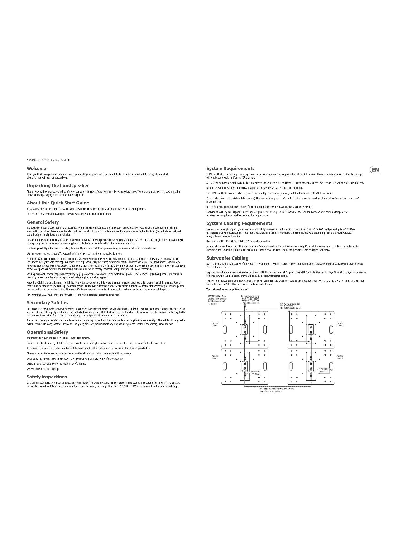
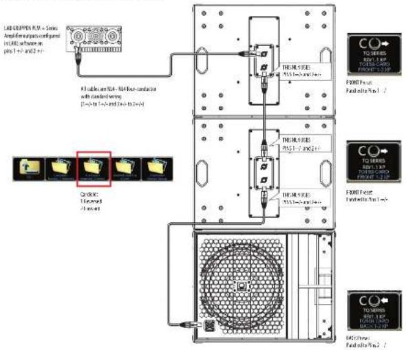
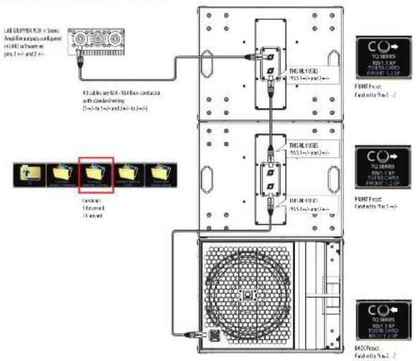
NOTE: Since the TQ15B/TQ18B subwoofer is wired 1+/- = LF and 2+/- = LINK, in order to power multiple enclosures, it is advised to construct SUB LINK cables wired: 2+->1+ and 2->1-.
To power two subwoofers per amplifier channel, standard NL4 link cables from Lab Gruppen BI-wired NL4 outputs (Channel 1 = 1+i; Channel 2 = 2+i) can be used in conjunction with a SUB LINK cable. Refer to wiring diagrams below for further details.
To power one subwoofer per amplifier channel, a single NL4 cable from Lab Gruppen bi-wired NL4 outputs (Channel 1 = 1+/-; Channel 2 = 2+/-) connects to the first subwoofer, then the SUB LINK cable connects to the second subwoofer.
Two subwoofers per amplifier channel
text_image
LED/SPRING/PROM + Series Amplifier output configured and USB software pin 1 42- and 2- to 3 Play Ring Channel 1 MIL-6 - MIL-6 transistor cable with start-up winding (0.5- to 1.5- and 2.4- to 3.0) Play Ring Channel 2 MIL-6 - MIL-6 transistor cable with start-up winding (0.5- to 1.5- and 2.4- to 3.0) Play Ring Channel 1 MIL-6 - MIL-6 transistor cable with start-up winding (0.5- to 1.5- and 2.4- to 3.0) MIL-6 - MIL-6 transistor cable with start-up winding (0.5- to 1.5- and 2.4- to 3.0)8 TQ13B and TQ18B Quick Stat. Guide 9
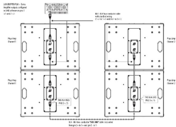
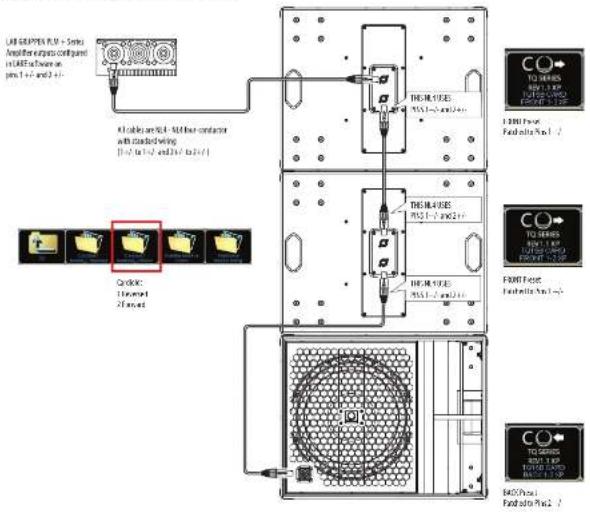
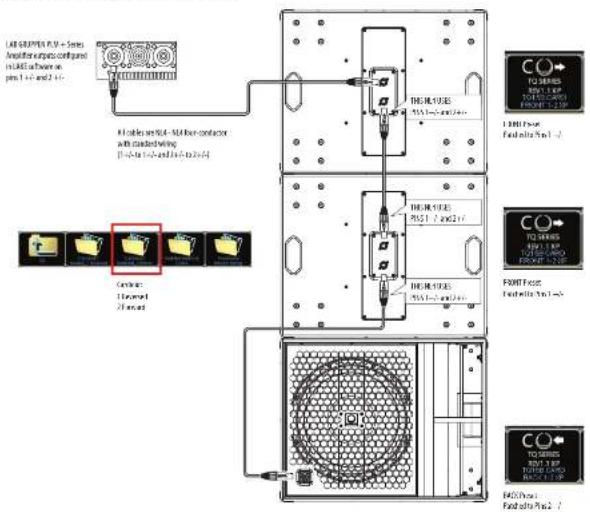
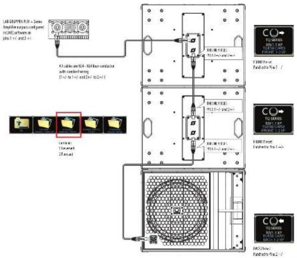
Cardiod BFF (back, forward, forward)
Using 4-Core NL4 cable, 2 DSP and 2 amplifier channels
text_image
LED SODIPEA PC16 - 5mm Amplifier output panel in MDE software on plus 1 +2 and 2 +3 File buttons are not to file one-order-on- with standard wiring [1-2] to [1-2] and [2-3] to [2+3] CD drive: 1.0mm x 2.0mm HDMI SIZE: 7551~8000 mm HDMI FLOW: 7551~8000 mm HDMI FLOW: 7551~8000 mm F2000 Front Foid into PC16 - 2 CD drives: 1.0mm x 2.0mm HDMI SIZE: 7551~8000 mm HDMI FLOW: 7551~8000 mm HDMI FLOW: 7551~8000 mm F2000 Front Foid into PC16 - 2 CD drives: 1.0mm x 2.0mm HDMI SIZE: 7551~7.5mm HDMI FLOW: 7551~7.5mm HDMI FLOW: 7551~7.5mm F2000 Front Foid into PC16 - 2
text_image
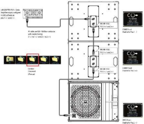
Output Configuration Species: Motor Outputs Power Outputs Control Power Outputs Power Outputs 4 TC100 CAFE - Low 1 - - - - - - - - - - - - - - - - - - - - - - - - - - - - - - - - - - - - - - - - - - - - - - Show Output Reading on Motor Panel Show Data to Output in Control PanelConnections
Caution: It is mandatory to use the official factory Lake pre-set. Failure to do so will result in component failure of the TQ passive crossover and transducers. No other 3rd party DSP or Amplifiers are supported

text_image
Mode T015B T0180 Back Panel T015B T0180 Front Panel Connector Input SUI → Input SUI Pins 2 x 1/2, can't connect to the IF error, they are just used to link. Internal schematic 10.4 10.4 10.4 10.4 10.4 10.4 10.4 10.4 10.4 10.4 10.4 10.4 10.4 10.4 10.4 10.4 10.4 10.4 10.4 10.4 10.4Rigging and Acoustic Simulation Software
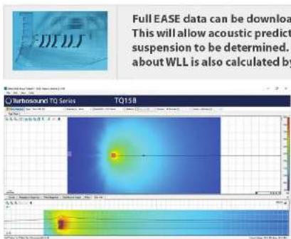
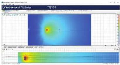
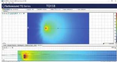
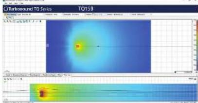
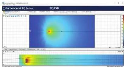
The TQ158/TQ18B is not an arrayable product. It is supported in Ease Focus 3, an acoustic simulation program, available as a free download from https://www.afmg.edu/en/ease-focus
text_image
Full EASE data can be download This will allow acoustic predict suspension to be determined. about WLL is also calculated by Turbosound TQ Series TQ15B10 TQ15B and TQ183
Quick Star Guide 11
Installation
Safety Warning: Only authorised and certified personnel shall design and install suspended configurations. Incorrect
installation may lead to death or permanent injury. The use of a secondary safety is a mandatory safety requirement if installing this product with the M10 rigging points.
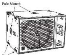
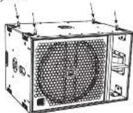
The TQ158/TQ188 has feet on the bottom for standing the speaker on a flat surface, two integral pole mount holes, and M10 mounting holes with fitted hex socket head screws.
text_image
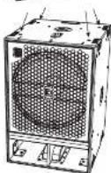
Pole Mount FootGroundstacking
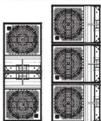
The TO15B/TO18B can be groundstacked in the horizontal or vertical orientation.
In the vertical orientation, try mounting two of them with the ports next to each other, as shown.
Suitable racket straps looped around the group of cabinets is advised as an additional safety measure.
natural_image
Pure electrical circuit lines without any symbolsBadge Rotation
The Turbosound badge is spring-loaded and can be rotated by hand to suit vertical or horizontal positioning.
Suspension
The TQ15B/TQ18B cabinets can be simply suspended using optional M10 shoulder eyebolts coupled to the internal rigging points provided. Remove the appropriate countersunk screws and replace them with eyebolts, which must have a thread length of at least 40 mm. Cabinets may be hung upside down if required.
Rigging Points
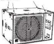
Eyebolts
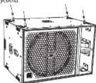

M10 Shoulder Eyebolt
40 mm
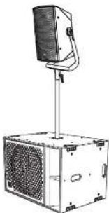
Pole Mount
Two 35 mm holes are provided for pole mounting.
We recommend using a 35 mm pole with an M20 thread at the lower end. This type provides more security and will screw into the top receptacle of the TQ15B/TQ18B.
natural_image
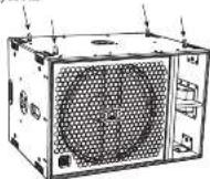
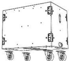
Line drawing of a desktop computer with a speaker and ventilation unit (no text or symbols)Transport Wheels (option)
An optional kit allows four wheels to be mounted as shown.
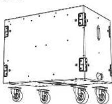
natural_image
Line drawing of a rectangular industrial cart with wheels and mounting holes (no text or symbols)Lake Preset Overlays and Application Notes
All TQ series loudspeakers exclusively use Lake XP pre-sets via Lab Gruppen PLV+ and D series L platforms and the forthcoming IPX HII-X pre-sets. No other amplifier and DSP platforms are supported.
The TO series has a powerful yet simple pre-set strategy utilizing the latest functionality of Lake software, along with new BLEO overlays.
Pre-set data is found either via the Lake Load Library, or can be downloaded from www.turbosound.com
T015B and T018B subwoofers each have individual 1 way passive FIR base pre-sets (1 channel DSP/AMP).
CAUTION: Do not combine TQ15B and TQ18B subwoofers on the same amplifier / DSP circuit. Failure to follow these instructions may lead to damage to the equipment.
CAUTION: Pay careful attention to output patching.
TQ15B and TQ18B modules are based on the XP module from Lake software.
This QSG refers to REV1.1 XP presets.
Lake software V7.0.7 or above must be used.
Lake XP signal flow:
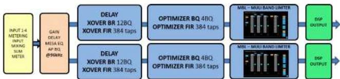
flowchart
graph LR
    A["INPUT 14 METERING INPUT MIXING SUM METER"] --> B["GAIN DELAY MESA EQ AP 8Q @96MHz"]
    B --> C1["DELAY XOVER BR 12BQ XOVER FIR 384 taps"]
    B --> C2["DELAY XOVER BR 12BQ XOVER FIR 384 taps"]
    C1 --> D1["OPTIMIZER BQ 4BQ OPTIMIZER FIR 384 taps"]
    C2 --> D2["OPTIMIZER BQ 4BQ OPTIMIZER FIR 384 taps"]
    D1 --> E1["MIL - MULI BAND LIMTER"]
    D2 --> E2["MIL - MULI BAND LIMTER"]
    E1 --> F1["DSP OUTPUT"]
    E2 --> F2["DSP OUTPUT"]
The download of the Lake controller Includes the Lake Controller Operation Manual, which is a full tutorial of the Lake Controller and compatible hardware such as PLV+ series amplifiers
Within this OSG, we focus on the Turbosound TO series workflow and pre-set strategy, and assume basic working knowledge of the Lake Controller.
| SUBVOOFER STRATEGYIllustrATION | |
| The TQ158-TQ188 subwoofers have a powerful yet simple Subwoofer pre-set strategy.Custains: I'm not combine TQ158 and TQ188 subwoofers on the same amplifier TSP circuit. | |
| Cardioled BFT:1 ratio1 cabinet facing Front, 1 cabinet facing Back- Effective cardioled portion- Good rear rejection- Some compromise of transience response- Less efficient use of subwoofers |  |
| Cardioled BFF2 ratio2 cabinets facing Front, 1 cabinet facing Back- Effective cardioled portion- Good rear rejection- Some compromise of transience response- The best ratio for efficient use | 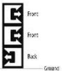 ____ ____ |
| Invented End Fire:1 ratioFront cabinets using FRONT presetRear cabinets using BTAR preset. Rear cabinets facing forward, at the rear to a cell inverted end fire array- Effective cardioled portion- Good rear rejection- Excellent transience response- Efficient use of subwoofers- More physical depth required (560 mm + 440 mm - 500mm) | 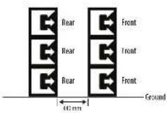 |
| Traditional- All cabinets facing Front- Effectively omnidirectional- Excellent transience response | 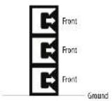 |
| SUBMOODER TIME ALIGNMENT/IllustrATION OVERLOR | ||
| The TC158R/TC168 subconverter pre-sets use all-pass filters to set the initial time alignment (assuming the fronts of the cabinets are in line) this generally reduces system accuracy. For example: If the fronts of the TC speaker and subconverter are aligned, then in both pre-sets, the delay should be set in the default, which is tens. However, it is not always possible to have the flown speakers and the ground standard less aligned in the vertical plane. 1. In this example, the sub is forward of the TQ speaker, and so the sub needs to be delayed. | 1. Sub forward |  Delay adjustment of subworkers Delay adjustment of subworkers |
Bienvenido
text_image
USB GRUPPER PLUG - Sinks Amplifier outputs configured in LIME software engine 1 +/- and +2 +/- Type Amp Channel 1 Type Amp Channel 1 Type Amp Channel 1 Type Amp Channel 2 Type Amp Channel 2 MA = M1.76-ox-conductor "SILL UIME" cable box wired from pin 2=1 to 1+ and pin 2=1 to 2-Cardiod BFF (back, forward, forward)
Using 4-Core NL4 cable, 2 DSP and 2 amplifier channels
text_image
LAB CRISPEN PLM + Series Amplification configuration intLAB software in plus 1+1 and 2+1 R1 blocks are BL-4. Not less conductor with standardizing [1-3 to 5-7 and 9-10 to 12-14] NEXT SERIES R1=1.2 NEXT SERIES R2=1.8 NEXT SERIES R3=2.0 NEXT SERIES R4=2.2 NEXT SERIES R5=2.4 NEXT SERIES R6=2.6 NEXT SERIES R7=2.8 NEXT SERIES R8=3.0 NEXT SERIES R9=3.2 NEXT SERIES R10=3.4 NEXT SERIES R11=3.6 NEXT SERIES R12=3.8 NEXT SERIES R13=4.0 NEXT SERIES R14=4.2 NEXT SERIES R15=4.4 NEXT SERIES R16=4.6 NEXT SERIES R17=4.8 NEXT SERIES R18=5.0 NEXT SERIES R19=5.2 NEXT SERIES R20=5.4 NEXT SERIES R21=5.6 NEXT SERIES R22=5.8 NEXT SERIES R23=6.0 NEXT SERIES R24=6.2 NEXT SERIES R25=6.4 NEXT SERIES R26=6.6 NEXT SERIES R27=6.8 NEXT SERIES R28=7.0 NEXT SERIES R29=7.2 NEXT SERIES R30=7.4 NEXT SERIES R31=7.6 NEXT SERIES R32=7.8 NEXT SERIES R33=8.0 NEXT SERIES R34=8.2 NEXT SERIES R35=8.4 NEXT SERIES R36=8.6 NEXT SERIES R37=8.8 NEXT SERIES R38=9.0 NEXT SERIES R39=9.2 NEXT SERIES R40=9.4 NEXT SERIES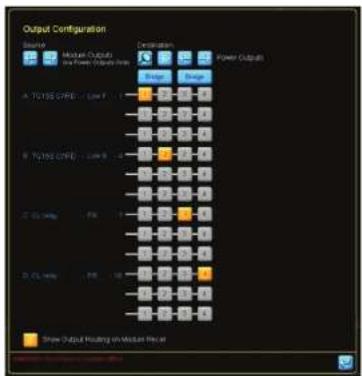
text_image
Output Configuration Balance Market Outputs and Power Outputs (Input) Configuration Power Outputs A. T0135 GPR - Low F - 1 B. T0135 GPR - Low B - 4 C. C-10000 - PR - 1 D. C-10000 - PR - 28 Show Output Resulting on Median FilterConexiones
Full EASE data can be downloaded from www.turbosound.com This will allow acoustic prediction, array formation and suspension to be determined. Important safety information about WLL is also calculated by EASE Focus.

text_image
Turboaround TQ Series TO15B T015B T015B T015B T015B T015B T015B T015B T015B T015B T015B T015B T015B T015B T015B T015B T015B T015BInstalación
natural_image
Line drawing of a desktop computer with a mounted monitor and base unit (no text or symbols)natural_image
Line drawing of a rectangular industrial cart with wheels and mounting holes (no text or symbols)text_image
LME GRIPPS P.N. 5 Series Amplifier outputs configured in LME software pin 1 -- and 2 + 4 Play Amp Channel 1 LME - MLE train condenser cable with standard winding (1+1- to 1+3 and 2+3- to 3+5) Play Amp Channel 2 LME - MLE train condenser "SHI" LME cable cross-wed from pin 2 to 1- and pin 2 to 1-Cardiod BFF (back, forward, forward)
Using 4-Core NL4 cable, 2 DSP and 2 amplifier channels
text_image
LED GRAPPER PLM + Series Analog input ports connected in L&E software on pins 1 to 2 and 3 to 4 F1 cables are 50A - 50Hz conductor with connection wiring (50A to 100A) and (50A to 20A) FIREL SIZE 100A-1.5mm x 2.5mm FIREL SIZE 100A-1.5mm x 2.5mm FIREL SIZE 100A-1.5mm x 2.5mm FIREL SIZE 100A-1.5mm x 2.5mm FIREL SIZE 100A-1.5mm x 2.5mm FIREL SIZE 100A-1.5mm x FIREL SIZE 100A-1.5mm x FIREL SIZE 100A-1.5mm x FIREL SIZE 100A-1.5mm x FIREL SIZE 100A-1.5mm x FIREL SIZE 100A-1.5mm x FIREL SIZE 100A-1.5mm x FIRELI SIZE 100A-1.5mm x FIRELI SIZE 100A-1.5mm x FIRELI SIZE 100A-1.5mm x FIRELI SIZE 100A-1.5mm x FIRELI SIZE 100A-1.5mm x FIRELI SIZE 100A-1.5mm x FIRELI SIZE 1, 2, 3, 4, 5, 6, 7, 8, 9, 10, 11, 12, 13, 14, 15, 16, 17, 18, 19, 20, 21, 22, 23, 24, 25, 26, 27, 28, 29, 30, 31, 32, 33, 34, 35, 36, 37, 38, 39, 40, 41, 42, 43, 44, 45, 46, 47, 48, 49, 50, 51, 52, 53, 54, 55, 56, 57, 58, 59, 60, 61, 62, 63, 64, 65, 66, 67, 68, 69, 70, 71, 72, 73, 74, 75, 76, 77, 78, 79, 80, 81, 82, 83, 84, 85, 86, 87, 88, 89, 90, 91, 92, 93, 94, 95, 96, 97, 98, 99, 100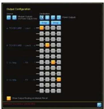
text_image
Output Configuration Reserve Motor Outputs and Power Outputs Color Power Outputs A: 70195.5/400 / Low 1 B: 70195.5/400 / Low 2 C: 70195.5/400 / Low 3 D: 70195.5/400 / Low 4 E: 70195.5/400 / Low 5 F: 70195.5/400 / Low 6 G: 70195.5/400 / Low 7 H: 70195.5/400 / Low 8 I: 70195.5/400 / Low 9 J: 70195.5/400 / Low 10 K: 70195.5/400 / Low 11 L: 70195.5/400 / Low 12 M: 70195.5/400 / Low 13 N: 70195.5/400 / Low 14 O: 70195.5/400 / Low 15 P: 70195.5/400 / Low 16 Q: 70195.5/400 / Low 17 R: 70195.5/400 / Low 18 S: 70195.5/400 / Low 19 T: 70195.5/400 / Low 20 U: 70195.5/400 / Low 21 V: 70195.5/400 / Low 22 W: 70195.5/400 / Low 23 X: 70195.5/400 / Low 24 Y: 70195.5/400 / Low 25 Z: 70195.5/400 / Low 26 A: High Output Raising on Motor Set at Description: Top level of MIMO-6.6Connexions
Full EASE data can be downloaded from www.turbosound.com. This will allow acoustic prediction, array formation and suspension to be determined. Important safety information about WLL is also calculated by EASE Focus.
natural_image
Technical line drawing of two industrial fan units with ventilation grilles and mounting brackets (no text or symbols)Eyebolts

M10 Shoulder Eyebolt
40 mm
Montage sur poteau
natural_image
Line drawing of a desktop audio workstation with a stand and speaker (no text or symbols)natural_image
Line drawing of a rectangular wheeled cart with wheels and side-mounted buttons (no text or symbols)Cardiod BFF (back, forward, forward)
Using 4-Core NL4 cable, 2 DSP and 2 amplifier channels
text_image
LRF GRIPTS PLM - Series Amplifier outputs contigand in LRF to have on pin 1-1 and 2-1 All cables are set - Not free conductor with claddinging [Pin 1-1 and 2-1] TREML SERIES TREML-1-1 and 2-1 TREML-2-1 TREML-3-1 and 2-1 TREML SERIES TREML-1-1 and 2-1 TREML SERIES TREML-2-1 and 2-1 TREML SERIES TREML-3-1 and 2-1 TREML SERIES TREML-4-1 and 2-1 TREML SERIES TREML-5-1 and 2-1 TREML SERIES TREML-6-1 and 2-1 TREML SERIES TREML-7-1 and 2-1 TREML SERIES TREML-8-1 and 2-1 TREML SERIES TREML-9-1 and 2-1 TREML SERIES TREML-10-1 and 2-1 TREML SERIES TREML-11-1 and 2-1 TREML SERIES TREML-12-1 and 2-1 TREML SERIES TREML-13-1 and 2-1 TREML SERIES TREML-14-1 and 2-1 TREML SERIES TREML-15-1 and 2-1 TREML SERIES TREML-16-1 and 2-1 TREML SERIES TREML-17-1 and 2-1 TREML SERIES TREML-18-1 and 2-1 TREML SERIES TREML-19-1 and 2-1 TREML SERIES TREML-20-1 and 2-1 TREML SERIES TREML-21-1 and 2-1 TREML SERIES TREML-22-1 and 2-1 TREML SERIES TREML-23-1 and 2-1 TREML SERIES TREML-24-1 and 2-1 TREML SERIES TREML-25-1 and 2-1 TREML SERIES TREML-26-1 and 2-1 TREML SERIES TREML-27-1 and 2-1 TREML SERIES TREML-28-1 and 2-1 TREML SERIES TREML-29-1 and 2-1 TREML SERIES TREML-30-1 and 2-1 TREML SERIES TREML-31-1 and 2-1 TREML SERIES TREML-32-1 and 2-1 TREML SERIES TREML-33-1 and 2-1 TREML SERIES TREML-34-1 and 2-1 TREML SERIES TREML-35-1 and 2-1 TREML SERIES TREML-36-1 and 2-1 TREML SERIES TREML-37-1 and 2-1 TREML SERIES TREML-38-1 and 2-1 TREML SERIES TREML-39-1 and 2-1 TREML SERIES TREML-40-1 and 2-1 TREML SERIES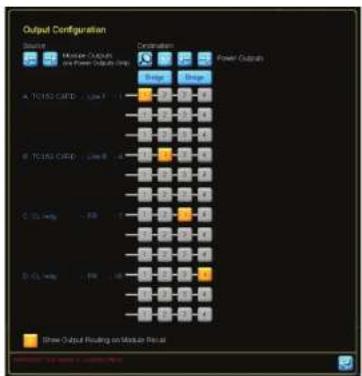
text_image
Output Configuration Source: Motor Output and Power Output Input Destination: Power Output Color A: TC1352-CRED - Low 1 B: TC1352-CRED - Low 8 C: CCL HWD - Low 1 D: CCL HWD - Low 8 Show Output Reading on Motor OutputAnschlüsse
text_image
Mode DC15M DC180 Back Panel DC15M DC180 Front Panel DC15M DC180 Back Panel DC15M DC180 Back Panel DC15M DC180 Back Panel DC15M DC180 Back Panel DC15M DC180 Back Panel DC15M DC180 Back Panel DC15M DC180 Back Panel DC15M DC180 Back Panel DC15M DC180 Back Panel DC20M DC200 Back Panel DC20M DC200 Back Panel DC20M DC200 Back Panel DC20M DC200 Back Panel DC20M DC200 Back Panel DC20M DC200 Back Panel DC20M DC200 Back Panel DC20M DC200 Back Panel DC20M DC200 Back panel DC20M DC200 Back panel DC20M DC200 Back panel DC20M DC200 Back panel DC20M DC200 Back panel DC20M DC200 Back panel DC20M DC200 Back panel DC20M DC200 Back panel DC20M DC200 Back panel DC25M DC250 Back panel DC25M DC250 Back panel DC25M DC250 Back panel DC25M DC250 Back panel DC30M DC300 Back panel DC30M DC300 Back panel DC30M DC300 Back panel DC30M DC300 Back panel DC35M DC350 Back panel DC35M DC350 Back panel DC35M DC350 Back panel DC35M DC350 Back panel DC35M DC350 Back panel DC40M DC400 Back panel DC40M DC400 Back panel DC40M DC400 Back panel DC45M DC450 Back panel DC45M DC450 Back panel DC45M DC450 Back panel DC45M DC450text_image
Full EASE data can be download This will allow acoustic predict suspension to be determined. about WLL is also calculated byInstallation
natural_image
Line drawing of a desktop computer with a speaker mounted on top (no text or symbols)natural_image
Line drawing of a rectangular industrial cart with wheels and mounting feet (no text or symbols)text_image
M4-56 Microcontroller Amplifier outputs configured in LIME software inputs 1 +/- to +2 to -1 M4-56 Microcondulator cable with standard wireg (3+3 to 1+3) and 2+3 to 2+3 M4-56 Microcondulator "540.100" cable cross wind from pin 2 to 1 and pin 2 to 1- M4-56 Microcondulator "540.100" cable cross windCardiod BFF (back, forward, forward)
Using 4-Core NL4 cable, 2 DSP and 2 amplifier channels
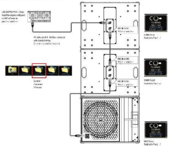
text_image
LED GRAPTE PLM + Single Amplifier outputs: configand m1.84E-6/4 have on pin 1 +1 and 2 +1 All cables are 50A - 34-inch conductor with conductivity. [10x10^3 / 2x10^3 / 3x10^3 / 4x10^3 / 5x10^3] Quick 110mm Forward DREAM SIZE PSS 1 - 2 and 2 +1 DREAM SIZE PSS 1 - 2 and 2 +1 DREAM SIZE PSS 1 - 2 and 2 +1 TO SERIES RDS 1.8XP TO SERIES RDS 1.8XP TO SERIES RDS 1.8XP TO SERIES RDS 1.8XP TO SERIES RDS 1.8XP TO SERIES RDS 1.8XP TO SERIES RDS 1.8XP TO SERIES RDS 1.8XP TO SERIES RDS 1.8XP TO SERIES RDS 1.8XP
text_image
Output Configuration Source: Motor Output and Power Output only Destination: Power Outputs Gray Orange A: TC152-CATD / Low 1 - - - - - - B: TC152-CATD / Low 2 - - - - C: C15 help - - - - D: C15 help - - - Other Output Reading as Median LinearConexões
text_image
Mode Back Panel and Front Panel Connector Internal Schematic T0150 T0180 Back Panel Hurticumund Input SHB+ Input SHB Pens 2 x 1/2, non-convert to the IF center, they are just used to link. T0150 T0180 Front Panel Net Conneurant Net Conneurant Front Input SHB + Front Input SHB - Internal Schematic HL4 HL6 HL4 HL6 HL4 HL6 HL4 HL6 HL4 HL6 HL4 HL6 HL4 HL6 HL4 HL6 HL4 HL6 HL4 HL6 HL4 HL6 HL4 HL6 HL4 HL6 HL4 HL6 HL4 HL6 HL4 HL6 HL4 HL6 HL4Full EASE data can be downloaded from www.turbosound.com. This will allow acoustic prediction, array formation and suspension to be determined. Important safety information about WLL is also calculated by EASE Focus.

text_image
TQ15B Turboquint TO Series TQ15B Temperature: 2000 Temperature: 2000 Temperature: 2000 Temperature: 2000 Temperature: 2000 Temperature: 2000 Temperature: 2000 Temperature: 2000 Temperature: 2000 Temperature: 2000 Temperature: 2000 Temperature: 2000 Temperature: 2000 Temperature: -2000 Temperature: -2000 Temperature: -2000 Temperature: -2000 Temperature: -2000 Temperature: -2000 Temperature: -2000 Temperature: -2000 Temperature: -2000 Temperature: -2000 Temperature: -2000 Temperature: -2000 Temperature: -200Instalação
natural_image
Line drawing of a desktop computer with a mounted microphone and ventilation grille (no text or symbols)natural_image
Line drawing of a rectangular industrial cart with wheels and mounting holes (no text or symbols)text_image
LUG50/PTFE16 + Series Amplifier output configured in LUG software as pin 1 +/- and +/- Play Amp Channel 1 MA-4-MA-4 power-conductor cable with standard wiring (Off: 30-12V, 24V, 21-6V) Play Amp Channel 1 MA-4-MA-4 power-conductor "MIL1800" cable connected from pin 1 to pin 4 and pin 2 to pin 1. MA-4-MA-4 power-conductor "MIL1800" cable connected from pin 1 to pin 4 and pin 2 to pin 1.Cardiod BFF (back, forward, forward)
Using 4-Core NL4 cable, 2 DSP and 2 amplifier channels

text_image
LAB DRIPPTES PLM + Series Amplifier outputs connected m1.841.1.1 hower on pin 1 +1 and 2 +1 41 cables and 50+ - N/A liner conductor with cladding wiring [Pin-1 to Pin-2 and Pin-3 to Pin-4] DRUM STRES 200.1~200.2/4 DRUM STRES 200.1~200.2/4 DRUM STRES 200.1~200.2/4 DRUM STRES 200.1~200.2/4 DRUM STRES 200.1~200.2/4 DRUM STRES 200.1~200.2/4 DRUM STRES (Pulsed) Pulsed by Puls 1 /2 DRUM STRES Pulsed by Puls 2 /3 DRUM STRES Pulsed by Puls 3 /4 DRUM STRES Pulsed by Puls 4 /5 DRUM STRES Pulsed by Puls 5 /6 DRUM STRES Pulsed by Puls 6 /7 DRUM STRES Pulsed by Puls 7 /8 DRUM STRES Pulsed by Puls 8 /9 DRUM STRES Pulsed by Puls 9 /10 DRUM STRES Pulsed by Puls 10 /11 DRUM STRES Pulsed by Puls 11 /12 DRUM STRES Pulsed by Puls 12 /13 DRUM STRES Pulsed by Puls 13 /14 DRUM STRES Pulsed by Puls 14 /15 DRUM STRES Pulsed by Puls 16 /17 DRUM STRES Pulsed by Puls 18 /19 DRUM STRES Pulsed by Puls 20 /21 DRUM STRES Pulsed by Puls 22 /23 DRUM STRES Pulsed by Puls 24 /25 DRUM STRES Pulsed by Puls 26 /27 DRUM STRES Pulsed by Puls 28 /29 DRUM STRES Pulsed by Puls 30 /31 DRUM STRES Pulsed by Puls 32 /33 DRUM STRES Pulsed by Puls 34 /35 DRUM STRES Pulsed by Puls 36 /37 DRUM STRES Pulsed by Puls 38 /39 DRUM STRES Pulsed by Puls 40 /41 DRUM STRES Pulsed by Puls 42 /43 DRUM STRES Pulsed by Puls 44 /45 DRUM STRES Pulsed by Puls 46 /47 DRUM STRES Pulsed by Puls 48 /49 DRUM STRES Pulsed by Puls 50 /51 DRUM STRES Pulsed by Puls 52 /53 DRUM STRES Pulsed by Puls 54 /55 DRUM STRES Pulsed by Puls 56 /57 DRUM STRES Pulsed by Puls 58 /59 DRUM STRES Pulsed by Puls 60 /61 DRUM STRES Pulsed by Puls 62 /63 DRUM STRES Pulsed by Puls 64 /65 DRUM STRES Pulsed by Puls 66 /67 DRUM STRES Pulsed by Puls 68 /69 DRUM STRES Pulsed by Puls 70 /71 DRUM STRES Pulsed by Puls 72 /73 DRUM STRES Pulsed by Puls 74 /75 DRUM STRES Pulsed by Puls 76 /77 DRUM STRES Pulsed by Puls 78 /79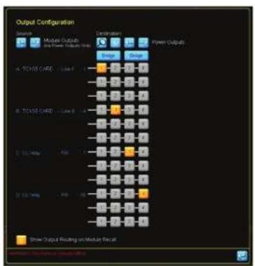
text_image
Output Configuration Reserve Module Outputs and Power Outputs Unit Configuration Power Outputs A: TC103 GADC - Low 1 B: TC103 GADC - Low 2 C: TC103 GADC - Low 3 D: TC103 GADC - Low 4 E: TC103 GADC - Low 5 F: TC103 GADC - Low 6 G: TC103 GADC - Low 7 Show Output Resulting on Module FccatConnessioni
text_image
Mode T015B T0180 Back Panel T015B T0180 Front Panel Connector Input SUI → Input SUI Pins 2 x 1/2 on wire connect to the IF encoder, they are just used to link. Internal Schematic 10.4 10.4 10.4 10.4 10.4 10.4 10.4 10.4 10.4 10.4 10.4 10.4 10.4 10.4 10.4 10.4 10.4 10.4 10.4 10.4 10.4Full EASE data can be downloaded from www.turbosound.com. This will allow acoustic prediction, array formation and suspension to be determined. Important safety information about WLL is also calculated by EASE Focus.

text_image
Turbosound TQ Series TQ15B Temperature: 20.000-30.000 (°C) Intensity: 100% Volume: 100% Volume: 100% Volume: 100% Volume: 100% Volume: 100% Volume: 100% Volume: 100% Volume: 100% Volume: 100% Volume: 100% Volume: 100% Volume: 100% Volume: 100% Volume: 100% Volume: -10.000 Volume: -10.000 Volume: -10.000 Volume: -10.000 Volume: -10.000 Volume: -10.000 Volume: -10.000 Volume: -10.000 Volume: -10.000 Volume: -10.000 Volume: -10.000Installazione
natural_image
Line drawing of a desktop computer with a speaker mounted on top (no text or symbols)natural_image
Line drawing of a four-wheeled cart with wheels and side-mounted buttons (no text or symbols)text_image
M4-200 Microcontroller Sensors Amplifier outputs configured in M4E software engine 1 +/- +/ - - - - - - M4-200 Micro conductor cable with standard wire (3+7 to 1+7) and (2+7 to 2+7) M4-200 Micro Channel 1 M4-200 Micro Channel 1 M4-200 Micro Channel 2 M4-200 Micro Channel 2 M4-200 Micro conductor "588 LMS" cable cross-wired bump per 2 to 1 and per 2 to 1Cardiod BFF (back, forward, forward)
Using 4-Core NL4 cable, 2 DSP and 2 amplifier channels

text_image
LAB CRUPTER PLM - Series Amplifier targets configuration in LAST tool on pre 1 + 2 and 3 + 4 All cables are UL - ML/linear conductor with standard wiring [10x10x10x10x10x10x10x10x10x10x10x10x10x10x10x10x10x10x10x10x10x10x10x10x10x10x10x10x10x10x10x10x10x10x COMETER Tensioned Fused THE MOUNT PSC1.7 and 2/4 THE MOUNT PSC1.7 and 2/4 THE MOUNT PSC1.7 and 2/4 THE MOUNT PSC1.7 and 2/4 THE MOUNT PSC1.7 and 2/4 THE MOUNT PSC1.7 and 2/4 THE MOUNT PSC1.7 and 2/4 THE MOUNT PSC1.5 and 2/4 THE MOUNT PSC1.5 and 2/4 THE MOUNT PSC1.5 and 2/4 THE MOUNT PSC1.5 and 2/4 THE MOUNT PSC1.5 and 2/4 THE MOUNT PSC1.5 and 2/4 THE MOUNT PSC1.5 and 2/4 THE MOUNT
text_image
Output Configuration Input Measure Outputs and Power Outputs Color Power Outputs A: TICESI CAFD - Type 1 B: TICESI CAFD - Type 2 C: GLU NG - Type 3 D: GLU NG - Type 4 Show Output Reading on Mode LinearAansluitingen
Full EASE data can be downloaded from www.turbosound.com. This will allow acoustic prediction, array formation and suspension to be determined. Important safety information about WLL is also calculated by EASE Focus.
text_image
Turbobound TQ Series TQ15B S - 0.0000 S - 0.0001 S - 0.0002 S - 0.0003 S - 0.0004 S - 0.0005 S - 0.0006 S - 0.0007 S - 0.0008 S - 0.0009 S - 0.0010 S - 0.0011 S - 0.0012 S - 0.0013 S - 0.0014 S - 0.0015 S - 0.0016 S - 0.0017 S - 0.0018 S - 0.0019 S - 0.0020 S - 0.0021 S - 0.0022 S - 0.0023 S - 0.0024 S - 0.0025 S - 0.0026 S - 0.0027 S - 0.0028 S - 0.0029 S - 0.0030 S - 0.0031 S - 0.0032 S - 0.0033 S - 0.0034 S - 0.0035 S - 0.0036 S - 0.0037 S - 0.0038 S - 0.0039 S - 0.0040 S - 0.0041 S - 0.0042 S - 0.0043 S - 0.0044 S - 0.0045 S - 0.0046 S - 0.0047 S - 0.0048 S - 0.0049 S - 0.0050 S - 0.0051 S - 0.0052 S - 0.0053 S - 0.0054 S - 0.0055 S - 0.0056 S - 0.0057 S - 0.0058 S - 0.0059 S - 0.0060 S - 0.0111 S - 1.7611Installatie
natural_image
Technical line drawing of a computer drive unit with ventilation grille and ports (no text or symbols)Grondstapeling
natural_image
Line drawing of a desktop audio workstation with a microphone and control panel (no text or symbols)natural_image
Line drawing of a rectangular industrial cart with wheels and mounting holes (no text or symbols)Lake Preset-Overlays en toepassingsopmerkingen
Cardiod BFF (back, forward, forward)
Using 4-Core NL4 cable, 2 DSP and 2 amplifier channels
text_image
LAD GNDPTES PL-18 - Series Amplifier units configured in LADET as shown on pre 1-2 and 3-4 File lists are NO. - Mitter conductor with marked wiring (10x10x10x10x10x10x10x10x10x10x10x10x10x10x10x10x10x10x10x10x10x10x10x10x10x10x10x10x10x10x10x10x10x10x CO pinout PL-18 PL-18 PL-18 PL-18 PL-18 PL-18 PL-18 PL-18 PL-18 PL-18 PL-18 PL-18 PL-18 PL-18 PL-18 PL-18 PL-18 PL-18 PL-18 PL-18 PL-16 PL-16 PL-16 PL-16 PL-16 PL-16 PL-16 PL-16 PL-16 PL-16 PL-16 PL-16 PL-16 PL-16 PL-16 PL-16 PL-16 PL-16 PL-16 PL-16 PL-15 PL-15 PL-15 PL-15 PL-15 PL-15 PL-15 PL-15 PL-15 PL-15 PL-15 PL-15 PL-15 PL-15 PL-15 PL-15 PL-15 PL-15 PL-15 PL-15 PL-14 PL-14 PL-14 PL-14 PL-14 PL-14 PL-14 PL-14 PL-14 PL-14 PL-14 PL-14 PL-14 PL-14 PL-14 PL-14 PL-14 PL-14 PL-14 PL-14 PL-13 PL-13 PL-13 PL-13 PL-13 PL-13 PL-13 PL-13 PL-13 PL-13 PL-13 PL-13 PL-13 PL-13 PL-13 PL-13 PL-13 PL-13 PL-13 PL-12 PL-12 PL-12 PL-12 PL-12 PL-12 PL-12 PL-12 PL-12 PL-12 PL-12 PL-12 PL-12 PL-12 PL-12 PL-12 PL-12 PL-12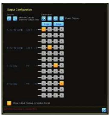
text_image
Output Configuration Select: Mixture Outputs and Power Outputs Generation: Voltage Range A: TC105-GWFD - Low R B: TC105-GWFD - Low B C: 3.5 Temp D: 3.5 Temp Show Output Flanking to Mixture FilterAnslutningar
Full EASE data can be downloaded from www.turbosound.com. This will allow acoustic prediction, array formation and suspension to be determined. Important safety information about WLL is also calculated by EASE Focus.
text_image
TQ150 Temperature: 24.000-30.000 Heatmap: 0.000-0.999 Color Scale: 0.000-0.999 Sensitivity: 0.000-0.999 Sensitivity: 0.000-0.999 Sensitivity: 0.000-0.999 Sensitivity: 0.000-0.999 Sensitivity: 0.000-0.999 Sensitivity: 0.000-0.999 Sensitivity: 0, 1, 2, 3, 4, 5, 6, 7, 8, 9, 10, 11, 12, 13, 14, 15, 16, 17, 18, 19, 20, 21, 22, 23, 24, 25, 26, 27, 28, 29, 30, 31, 32, 33, 34, 35, 36, 37, 38, 39, 40, 41, 42, 43, 44, 45, 46, 47, 48, 49, 50, 51, 52, 53, 54, 55, 56, 57, 58, 59, 60, 61, 62, 63, 64, 65, 66, 67, 68, 69, 70, 71, 72, 73, 74, 75, 76, 77, 78, 79, 80, 81, 82, 83, 84, 85, 86, 87, 88, 89, 90, 91, 92, 93, 94, 95, 96, 97, 98, 99, 100Installation
natural_image
Line drawing of a desktop computer with a speaker mounted on top, no text or symbols presentTransporthjul (tillval)
natural_image
Line drawing of a four-wheeled cart with wheels and handle (no text or symbols)text_image
USB GRUPEEN PLV + Series Amplifier outputs configured in USB software or pin 1 +/- and -1 +/- Fays Amp Channel 1 Fays Amp Channel 2 Fays Amp Channel 3 FOS NLS055 PRO 2-/-2- R4.4-16.4 non-conductor cable with standard winding (1+1-1 to 1-1 and 2+1-2 to 2+2) FOS NLS055 PRO 1-/-1- R4.4-16.4 non-conductor "USB UMAP" cable cross-weld from pin 1 to 1-1 and pin 2 to 1-1Cardiod BFF (back, forward, forward)
Using 4-Core NL4 cable, 2 DSP and 2 amplifier channels
text_image
LAB GROUP/PLM - Sensor Amplifier output configuration in LABE software on plus 1 +1 and 2 +1 A1 cable is 504 - 964 line conductor with cooling (10x1 to 1x2 and 2x3 to 2x4) Circuit: 11 microamm 2 microamm HEIML SERIES 10.5 x 1-0 and 2 x 1 HEIML SERIES 10.5 x 1-0 and 2 x 1 HEIML SERIES 10.5 x 1-0 and 2 x 1 F2001 Power Fusolite Pin 1 /- F2001 Fuses Fusolite Pin 2 /- F2001 Fuses Fusolite Pin 3 /- F2001 Fuses Fusolite Pin 4 /- F2001 Fuses Fusolite Pin 5 /- F2001 Fuses Fusolite Pin 6 /- F2001 Fuses Fusolite Pin 7 /- F2001 Fuses Fusolite Pin 8 /- F2001 Fuses Fusolite Pin 9 /- F2001 Fuses Fusolite Pin 10 /- F2001 Fuses Fusolite Pin 11 /- F2001 Fuses Fusolite Pin 12 /- F2001 Fuses Fusolite Pin 13 /- F2001 Fuses Fusolite Pin 14 /- F2001 Fuses Fusolite Pin 15 /- F2001 Fuses Fusolite Pin 16 /- F2001 Fuses Fusolite Pin 17 /- F2001 Fuses Fusolite Pin 18 /- F2001 Fuses Fusolite Pin 19 /- F2001 Fuses Fusolite Pin 20 /- F2001 Fuses Fusolite Pin 21 /- F2001 Fuses Fusolite Pin 22 /- F2001 Fuses Fusolite Pin 23 /- F2001 Fuses Fusolite Pin 24 /- F2001 Fuses Fusolite Pin 25 /- F2001 Fuses Fusolite Pin 26 /- F2001 Fuses Fusolite Pin 27 /- F2001 Fuses Fusolite Pin 28 /- F2001 Fuses Fusolite Pin 29 /- F2001 Fuses Fusolite Pin 30 /- F2001 Fuses Fusolite Pin 31 /- F2001 Fuses Fusolite Pin 32 /- F2001 Fuses Fusolite Pin 33 /- F2001 Fuses Fusolite Pin 34 /- F2001 Fuses Fusolite Pin 35 /- F2001 Fuses Fusolite Pin 36 /- F2001 Fuses Fusolite Pin 37 /- F2001 Fuses Fusolite Pin 38 /- F2001 Fuses Fusolite Pin 39 /- F2001 Fuses Fusolite Pin 40 /- F2001 Fuses Fusolite Pin 41 /- F2001 Fuses Fusolite Pin 42 /- F2001 Fuses Fusolite Pin 43 /- F2001 Fuses Fusolite Pin 44 /- F2001 Fuses Fusolite Pin 45 /- F2001 Fuses Fusolite Pin 46 /- F2001 Fuses Fusolite Pin 47 /- F2001 Fuses Fusolite Pin 48 /- F2001 Fuses Fusolite Pin 49 /- F2001 Fuses Fusolite Pin 50 /- F2001 Fuses Fusolite Pin 51 /- F2001 Fuses Fusolite Pin 52 /- F2001 Fuses Fusolite Pin 53 /- F2001 Fuses Fusolite Pin 54 /- F2001 Fuses Fusolite Pin 55 /- F2001 Fuses Fusolite Pin 56 /- F2001 Fuses Fusolite Pin 57 /- F2001 Fuses Fusolite Pin 58 /- F2001 Fuses Fusolite Pin 59 /- F2001 Fuses Fusolite Pin 60 /- F2001 Fuses Fusolite Pin 61 /- F2001 Fuses Fusolite Pin 62 /- F2001 Fuses Fusolite Pin 63 /- F2001 Fuses Fusolite Pin 64 /- F2001 Fuses Fusolite Pin 65 /- F2001 Fuses Fusolite Pin 66 /- F2001 Fuses Fusolite Pin 67 /- F2001 Fuses Fusolite Pin 68 /- F2001 Fuses Fusolite Pin 69 /- F2001 Fuses Fusolite Pin 70 /- F2001 Fuses Fusolite Pin 71 /- F2001 Fuses Fusolite Pin 72 /- F2001 Fuses Fusolite Pin 73 /- F2001 Fuses Fusolite Pin 74 /- F2001 Fuses Fusolite Pin 75 /- F2001 Fuses Fusolite Pin 76 /- F2001 Fuses Fusolite Pin 77 /- F2001 Fuses Fusolite Pin 78 /- F2001 Fuses Fusolite Pin 79 /- F2001 Fuses Fusolite Pin 80 /- F2OCH/Heat: Heat: Heat: Heat: Heat: Heat: Heat: Heat: Heat: Heat: Heat: Heat: Heat: Heat: Heat: Heat: Heat: Heat: Heat: Heat: Heat: Heat: Heat: Heat: Heat: Heat: Heat: Heat: Heat: Heat: Heat: Heat: Heat: Heat: Thermal Control Panel (P) - Series (A) - Series (B) - Series (C) - Series (D) - Series (E) - Series (G) - Series (H) - Series (I) - Series (J) - Series (K) - Series (L) - Series (M) - Series (N) - Series (O) - Series (P) - Series (Q) - Series (R) - Series (S) - Series (T) - Series (U) - Series (V) - Series (W) - Series (X) - Series (Y) - Series (Z) - Series (A) - Series (B) - Series (C) - Series (D) - Series (E) - Series (G) - Series (H) - Series (I) - Series (J) - Series (K) - Series (L) - Series (M) - Series (N) - Series (O) - Series (P) - Series (Q) - Series (R) - Series (S) - Series (T) - Series (V) - Series (W) - Series (X) - Series (Y) - Series (Z) - Series (A) - Series (B) - Series (C) - Series (D) - Series (E) - Series (G) - Series (H) - Series (I) - Series (J) - Series (K) - Series (L) - Series (M) - Series (N) - Series (O) - Series (R) - Series (S) - Series (T) - Series (U) - Series (V) - Series (W) - Series (X) - Series (Y) - Series (Z) - Series (A) - Series (B) - Series (C) - Series (D) - Series (E) - Series (G) - Series (H) - Series (I) - Series (J) - Series (K) - Series (S) - Series (T) - Series (U) - Series (V) - Series (W) - Series (X) - Series (Y) - Series (Z) - Series (A) - Series (B) - Series (C) - Series (D) - Series (E) - Series (G) - Series (H) - Series (I) - Series (J) - Series (K) - Series (S) - Series (U) - Series (V) - Series (W) - Series (X) - Series (Y) - Series (Z) - Series (A) - Series (B) - Series (C) - Series (D) - Series (E) - Series (G) - Series (H) - Series (I) - Series (J) - Series (K) - Series (S) - Series (T) - Series (U) - Series (W) - Series (X) - Series (Y) - Series (Z) - Series (A) - Series (B) - Series (C) - Series (D) - Series (E) - Series (G) - Series (H) - Series (I) - Series (J) - Series (K) - Series (S) - Series (T) - Series (U) - Series (V) - Series (W) - Series (Z) - Series (A) - Series (B) - Series (C) - Series (D) - Series (E) - Series (G) - Series (H) - Series (I) - Series (J) - Series (K) - Series (S) - Series (T) - Series (U) - Series (V) - Series (W) - Series (X) - Series (Y) - Series (Z)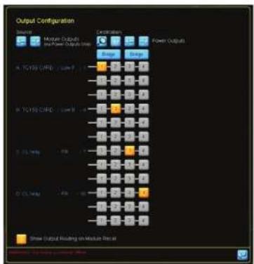
text_image
Output Configuration Settings Motion Outputs and Power Outputs S Destination Power Outputs A: TC150 C/PC - Low P B: TC150 C/PC - Low B C: TC150 C/PC - Low A D: TC150 C/PC - Low B E: TC150 C/PC - Low A Show Output Resulting on Module Logic Source: TC150 C/PC - Low PPodłączenia
text_image
Mode T015B T0180 Back Panel T015B T0180 Front Panel Connector Input SUI → Input SUI Pins 2 x 1/2 on wire connect to the IF encoder, they are just used to link. Internal schematic 10.4 10.4 10.4 10.4 10.4 10.4 10.4 10.4 10.4 10.4 10.4 10.4 10.4 10.4 10.4 10.4 10.4 10.4 10.4 10.4 10.4Full EASE data can be downloaded from www.turbosound.com. This will allow acoustic prediction, array formation and suspension to be determined. Important safety information about WLL is also calculated by EASE Focus.

text_image
TurboKnock TQ Series TQ15B Temperature: 20.000-24.000 Volume: 100000000 Volume: 100000000 Volume: 100000000 Volume: 100000000 Volume: 100000000 Volume: 100000000 Volume: 100000000 Volume: 100000000 Volume: 1,000,000 Volume: 1,500,000 Volume: 2,000,000 Volume: 2,500,000 Volume: 3,000,000 Volume: 3,500,000 Volume: 4,000,000 Volume: 4,500,000 Volume: 5,000,000 Volume: 5,500,000 Volume: 6,000,000 Volume: 6,500,000 Volume: 7,000,000 Volume: 7,500,000 Volume: 8,000,000 Volume: 8,500,000 Volume: 9,000,000 Volume: 9,500,000 Volume: 1,5,555,555 Volume: 2,5,555,555 Volume: 3,5,555,555 Volume: 4,5,555,555 Volume: 5,5,555,555 Volume: 6,5,555,555 Volume: 7,5,555,555 Volume: 8,5,555,555 Volume: 9,5,555,555 Volume: 12,5,555,555 Volume: 13,5,555,555 Volume: 14,5,555,555 Volume: 16,5,555,555 Volume: 18,5,555,555 Volume: 21,5,555,555 Volume: 23,5,555,555 Volume: 26,5,555,555 Volume: 29,5,555,555 Volume: 32,5,555,555 Volume: 36,5,555,555 Volume: 41,5,566,666 Volume: 46,6,666,666 Volume: 49,7,666,666 Volume: 49.7 Volume: 49.7 Volume: 49.7 Volume: 49.7 Volume: 49.7 Volume: 49.7 Volume: 49.7 Volume: 49.7 Volume: 49.7 Volume: 49.7 Volume: 49.7 Volume: 49.7 Volume: 49.7 Volume: -12.2% Volume: -12.2% Volume: -12.2% Volume: -12.2% Volume: -12.2% Volume: -12.2% Volume: -12.2% Volume: -12.2% Volume: -12.2% Volume: -12.2% Volume: -12.2% Volume: -12.2% Volume: -12.2% Volume: -8.8% Volume: -8.8% Volume: -8.8% Volume: -8.8% Volume: -8.8% Volume: -8.8% Volume: -8.8% Volume: -8.8% Volume: -8.8% Volume: -8.8% Volume: -8.8% Volume: -8.8% Volume: -8.8% Volume: -8.8% Volume: -8.8% Variance (x-axis) = Variance (y-axis) Balance (x-axis) = Balance (y-axis) Balance (x-axis) = Balance (y-axis) Balance (x-axis) = Balance (y-axis) Balance (x-axis) = Balance (y-axis) Balance (x-axis) = Balance (y-axis) Balance (x-axis) = Balance (y-axis) Balance (x-axis) = Balance (y-axis) Balance (x-axis) = Balance (y-axis) Balance (x-axis) = Balance (y-axis) Balance (x-axis) = Balance( y-axis) Balance (x-axis) = Balance( y-axis) Balance (x-axis) = Balance( y-axis) Balance (x-axis) = Balance( y-axis) Balance (x-axis) = Balance( y-axis) Balance (x-axis) = Balance( y-axis) Balance (x-axis) = Balance( y-axis) Balance (x-axis) = Balance( y-axis) Balance (x-axis) = Balance( y-axis) Balance (x-axis) = Balance( y axis) Balance (x-axis) = Balance( x axis) Balance (x-axis) = Balance( x axis) Balance (x-axis) = Balance( x axis) Balance (x-axis) = Balance( x axis) Balance (x-axis) = Balance( x axis) Balance (x-axis) = Balance( x axis) Balance (x-axis) = Balance( x axis) Balance (x-axis) = Balance( x axis) Balance (x-axis) = Balance( x axis) Balance (x-axis) = Balance( x axes) Balance (x-axis) = Balance( x axes) Balance (x-axis) = Balance( x axes) Balance (x-axis) = Balance( x axes) Balance (x-axis) = Balance( x axes) Balance (x-axis) = Balance( x axes) Balance (x-axis) = Balance( x axes) Balance (x-axis) = Balance( x axes) Balance (x-axis) = Balance( x axes) Balance (x-axis) = Balance( x axes)Instalacja
natural_image
Line drawing of a desktop computer with a speaker mounted on top (no text or symbols)natural_image
Line drawing of a rectangular industrial cart with wheels and mounting holes (no text or symbols)64 TC153 and TC193 65
クイックス タートガイド
text_image
USB GRIFF/FLU + Series Amplifier outputs configured or IAE software on input 1 to 2 and 3 to 4 All cables are TU - No other conductor with standard wiring (1 to 2 to 3 to 4 and 2 to 3 to 4) Control 1 Receiver 2 Receiver The 10A-10B5 FRE 1 to 2 and 3 The 10A-10B5 FRE 1 to 2 and 3 The 10A-10B5 FRE 1 to 2 and 3 The 10A-10B5 FRE 1 to 2 and 3 The 10A-10B5 FRE 1 to 2 and 3 The 10A-10B5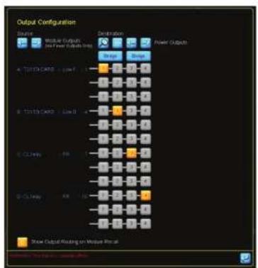
text_image
Output Configuration Project: Module Outputs Job Power Outputs Int Color Power Outputs A: TOTTER CARD - Low F - - - - - - - - - - - - - - - - - - - - - - - - - - - - - - - - - - - - - - - - - - - - - - - - - - - - - - - - - - - - - - - - - - - - - - - - - - - - - - - - - Show Output Rooting on Multiple Process接続
text_image
Mode Back Panel and Front Panel Connector Internal Schematic 10158 10188 Back Panel Turboelectric Input SUI + Input SIB Pens 2 x 1/2, cut out, connect to the IF center, they are just used to link. 10158 10188 Front Panel Net Connectors Net Connectors Front Input SUI + Front Input SIB - 10.4 Input 10.4 Input 10.4 InputFull EASE data can be downloaded from www.turbosound.com. This will allow acoustic prediction, array formation and suspension to be determined. Important safety information about WLL is also calculated by EASE Focus.
text_image
Turboaround TC Series TQ15B File Edit View Help View 1 View 2 View 3 View 4 View 5 View 6 View 7 View 8 View 9 View 10 View 11 View 12 View 13 View 14 View 15 View 16 View 17 View 18 View 19 View 20 View 21 View 22 View 23 View 24 View 25 View 26 View 27 View 28 View 29 View 30 View 31 View 32 View 33 View 34 View 35 View 36 View 37 View 38 View 39 View 40 View 41 View 42 View 43 View 44 View 45 View 46 View 47 View 48 View 49 View 50 View 51 View 52 View 53 View 54 View 55 View 56 View 57 View 58 View 59 View 60 View 61 View 62 View 63 View 64 View 65 View 66 View 67 View 68 View 69 View 70 View 71 View 72 View 73 View 74 View 75 View 76 View 77 View 78 View 79 View 80 View 81 View 82 View 83 View 84 View 85 View 86 View 87 View 88 View 89 View 90 View 91 View 92 View 93 View 94 View 95 View 96 View 97 View 98 View 99 View 10066 TC13 and TC18 67
クイックス タートガイド
インストール
natural_image
Three identical diagrams showing a circular fan or vent with grid patterns, arranged vertically (no text or symbols)バッジの回転
natural_image
Line drawing of a computer monitor mounted on a base unit (no text or symbols)@送ホイール (オプション)
natural_image
Line drawing of a rectangular industrial cart with wheels and mounting holes (no text or symbols)text_image
USB/UPPERUM + Series amplifier output configured in LME software units 1 (1-2) and (3-4) Display Channel 1 Display Channel 2 Display Channel 1 Display Channel 2 MIL-10.10 microconductor with linear lead winding (1-2) and (3-4) and (3-5) and (3-6) and (3-7) MIL-10.10 microconductor "300 LPS" cable required from 2 to 1+200 ps 2 to 3.72 TQ15B and TQ18B 73
text_image
LAB DRIPPER PLN + Series Amplifier outputs configuration int: 1000 software on plus 1 to 2 and 3 rows 41 tables on 104.16/48/1988 conductor with constant wiring (3x-1 to 1x-2 and 1x-3 to 5x) Cable: 1.1 micro 2.1 micro THEA FUSE PLN 1.2 and 2.1c THEA FUSE PLN 1.2 and 2.1c THEA FUSE PLN 1.2 and 2.1c L 2000 Power Foid output Pin 1 /2 L 2000 Power Foid output Pin 2 /2 L 2000 Power Foid output Pin 3 /2 MOS Cone PLN 1.2 and 2.1c MOS Cone PLN 1.2 and 2.1c
text_image
Output Configuration Volume Mixture Outputs and Power Outputs (Max) Description Power Output Color A: T/O/SE CAFE / Low 1 B: T/O/SE CAFE / Low 2 C: 0.5 mm D: 0.5 mm E: 0.5 mm Show Output Reading on Module Recal快速启动向开
连接
text_image
Full EASE data can be download This will allow acoustic predict suspension to be determined. about WLL is also calculated by74 TC153 and TQ186 75
快速启动向开
安装

安全警告
natural_image
Three identical diagrams showing a circular fan pattern with internal grid patterns, no text or symbols present.徽章轮换
natural_image
Line drawing of a desktop audio workstation with a speaker and sound unit (no text or symbols)运输轮可选
可选套件允许安装四个轮子,如图所示。
Eyebolts

M10 Shoulder Eyebolt
natural_image
Line drawing of a four-wheeled cart with wheels and side-mounted buttons (no text or symbols)Lake 预设叠加和应用说明
| System | ||
| Frequency response (-1.3 dB)* 45 Hz - 120 Hz | 10 Hz - 120 Hz | |
| Frequency response (-10 dB)* 37 Hz - 200 Hz | 52 Hz - 200 Hz | |
| Nominal dispersion (8 - 6 dB pixels) Omni | ||
| Power handling (IIC) * 300 W continuous | 1000 V/Continuous | |
| Sensitivity (10^9 m^-2) | 28 dB | 96.5 dB |
| Maximum SFP | 138 dB peak | 138 dB peak |
| Impedance | 8.0 | |
| Components | 1 x 18" (350 mm) Yes LP driver | 1 x 18" (460 mm) Yes LP driver |
| Endurance | ||
| Connections | 3 x Restnut speed/04" N/L | |
| Wire ring | Plats 1+/-1- Input, plats 2+/-2- link, from plats 2+/-2- | |
| Dimensions HVO | 525 x 665 x 560 (25.66 x 26.18 x 22.04") | 525 x 785 x 560 (25.86 x 30.8 x 22.04") |
| Net weight | 37.1 kg (61.8 lbs) | 40.7 kg (85.7 lbs) |
| Construction | 15 mm and 18 mm (%' and %') plywood | |
| Finish | P/U Semi mat black paint | |
| Grille | Powder coated perforated steel, cloth wrapped | |
| Drying hardware | MIO x 16 Pants | |
| IP rating | IP44 | |
| DW rating | 4.5 (XSTM G155 13) | |
| Accessories (optional) | ||
| Bag | T0150-WPC | T0150-WPC |
| Wheels | Manchester wheel kit | |
Notes:
1. Average over stated bandwidth. Measured at 1 metre on axis.
2. SPL level at 1 m under free field conditions, using pink noise with crest factor 4, with dedicated pre-set
3. Peak level at 1 m under hall space conditions using pink noise with crest factor 4, with dedicated pre-set.
4. Passive Power handling is combined LT/FF on dedicated preset with (ECI)
5. Case Data can be downloaded from www.turioscund.com
Other important information

Important information
-
Register online. Please register your new Music Tribe equipment right after you purchase it by visiting musctribe.com. Registering your purchase using our simple online form helps us to process your repair claims more quietly and efficiently. Also, read the terms and conditions of our warranty, if applicable.
-
Malfunction. Should your Music Tribe Authorized Reveller not be installed in your vicinity, you may contact the Music Tribe Authorized Further for your country listed under "Support" at musicite.com. Should your country not be listed, please check if your problem can be dealt with by our "Online Support" which may also be found under "Support" at musicite.com. Alternatively, please submit an online warranty claim at musicite.com BEFORE returning the product.

Informations importantes
Hereby, Music Tribe declares that this product is in compliance with Directive
2011/65/EU and Amendment 2015/B63/EU, Directive 2012/19/EU, Regulation
519/2012 REACH SWHC and Directive 1907/2006/LC, and this passive product is not
applicable to EMC Directive 2014/30/EU, LV Directive 2014/35/EU.
Full text of ELL DeC is available at https://community.musictribe.com/
EU Representative: Music Tribe Brands DK A/S
Address: Gammel Strand 44, DK-1202 Kobenhavn K, Denmark
UK Representative: Music Tribe Brands UK Ltd.
Address: 8th Floor, 20 Farrington Street, London EC4A 405, United Kingdom
EN