SV12V - Sander HiKOKI - Free user manual and instructions
Find the device manual for free SV12V HiKOKI in PDF.

User questions about SV12V HiKOKI
0 question about this device. Answer the ones you know or ask your own.
Ask a new question about this device
Download the instructions for your Sander in PDF format for free! Find your manual SV12V - HiKOKI and take your electronic device back in hand. On this page are published all the documents necessary for the use of your device. SV12V by HiKOKI.
USER MANUAL SV12V HiKOKI
natural_image
Line drawing of a mechanical power tool with a lever and base plate (no text or symbols)
en Handling instructions
de Bedienungsanleitung
fr Mode d'emploi
it Istruzioni per l'uso
nl Gebruiksaanwijzing
es Instrucciones de manejo
pt Instruções de uso
sv Bruksanvisning
da Brugsanvisning
no Bruksanvisning
fi Käyttöohjeet
el Οδηγίες χειρισμού


(Original instructions)
GENERAL POWER TOOL SAFETY WARNINGS

WARNING
Read all safety warnings, instructions, illustrations and specifications provided with this power tool.
Failure to follow all instructions listed below may electric shock, fire and/or serious injury.
Save all warnings and instructions for future reference.
The term “power tool” in the warnings refers to your mains-operated (corded) power tool or battery-operated (cordless) power tool.
1) Work area safety
a) Keep work area clean and well lit.
Cluttered or dark areas invite accidents.
b) Do not operate power tools in explosive atmospheres, such as in the presence of flammable liquids, gases or dust.
Power tools create sparks which may ignite the dust or fumes.
c) Keep children and bystanders away while operating a power tool.
Distractions can cause you to lose control.
2) Electrical safety
a) Power tool plugs must match the outlet. Never modify the plug in any way. Do not use any adapter plugs with earthed (grounded) power tools.
Unmodified plugs and matching outlets will risk of electric shock.
b) Avoid body contact with earthed or grounded surfaces, such as pipes, radiators, ranges and refrigerators.
There is an increased risk of electric shock body is earthed or grounded.
c) Do not expose power tools to rain or wet conditions.
Water entering a power tool will increase the risk of electric shock.
d) Do not abuse the cord. Never use the cord for carrying, pulling or unplugging the power tool.
Keep cord away from heat, oil, sharp edges or moving parts.
Damaged or entangled cords increase the risk electric shock.
e) When operating a power tool outdoors, use an extension cord suitable for outdoor use.
Use of a cord suitable for outdoor use reduces the risk of electric shock.
f) If operating a power tool in a damp location is unavoidable, use a residual current device (RCD) protected supply.
Use of an RCD reduces the risk of electric shock.
3) Personal safety
a) Stay alert, watch what you are doing and use common sense when operating a power tool. Do not use a power tool while you are tired or under the influence of drugs, alcohol or medication.
A moment of inattention while operating power tools may result in serious personal injury.
b) Use personal protective equipment. Always wear eye protection.
Protective equipment such as a dust mask, non-skid safety shoes, hard hat or hearing protection used for appropriate conditions will reduce personal injuries.
c) Prevent unintentional starting. Ensure the switch is in the off-position before connecting to power source and/or battery pack, picking up or carrying the tool.
Carrying power tools with your finger on the switch or energising power tools that have the switch invites accidents.
desh Remove any adjusting key or wrench before turning the power tool on.
A wrench or a key left attached to a rotating part of the power tool may result in personal injury.
e) Do not overreach. Keep proper footing and balance at all times.
This enables better control of the power tool unexpected situations.
f) Dress properly. Do not wear loose clothing or jewellery. Keep your hair and clothing away from moving parts.
Loose clothes, jewellery or long hair can be caught in moving parts.
g) If devices are provided for the connection of dust extraction and collection facilities, ensure these are connected and properly used.
Use of dust collection can reduce dust-related hazards.
h) Do not let familiarity gained from frequent use of tools allow you to become complacent and ignore tool safety principles.
A careless action can cause severe injury with fraction of a second.
4) Power tool use and care
reduce Do not force the power tool. Use the correct power tool for your application.
The correct power tool will do the job better and safer at the rate for which it was designed.
b) Do not use the power tool if the switch does not if turnout on and off.
Any power tool that cannot be controlled with switch is dangerous and must be repaired.
c) Disconnect the plug from the power source and/or remove the battery pack, if detachable, from the power tool before making any adjustments, changing accessories, or storing power tools.
Such preventive safety measures reduce the risk of starting the power tool accidentally.
d) Store idle power tools out of the reach of children and do not allow persons unfamiliar with the power tool or these instructions to operate the power tool.
Power tools are dangerous in the hands of untrained users.
e) Maintain power tools and accessories. Check for misalignment or binding of moving parts, breakage of parts and any other condition that may affect the power tool's operation. If damaged, have the power tool repaired before use.
Many accidents are caused by poorly maintain power tools.
f) Keep cutting tools sharp and clean.
Properly maintained cutting tools with sharp cutting edges are less likely to bind and are easier to control.
g) Use the power tool, accessories and tool bits etc. in accordance with these instructions, taking into account the working conditions and the work to be performed.
Use of the power tool for operations different those intended could result in a hazardous situation.
h) Keep handles and grasping surfaces dry, clean and free from oil and grease.
Slippery handles and grasping surfaces do allow for safe handling and control of unexpected situations.
5) Service
a) Have your power tool serviced by a qualified repair person using only identical replacement parts.
This will ensure that the safety of the power maintained.
PRECAUTION
Keep children and infirm persons away.
When not in use, tools should be stored out of reach of children and infirm persons.
ADDITIONAL SAFETY WARNINGS
- Ensure that the power source to be utilized conforms to the power requirements specified on the product nameplate.
- Ensure that the power switch is in the OFF position.
If the plug is connected to a receptacle while the power switch is in the ON position, the power tool will start operating immediately, which could cause a serious accident.
- When the work area is removed from the power source, use an extension cord of sufficient thickness and rated capacity. The extension cord should be kept as short as practicable.
- Prior to the sanding operation, make sure the material you are going to sand.
If generation of harmful/toxic dusts such as lead paint, woods and metals is expected under the sanding operation, make sure the dust bag or appropriate dust extraction system is connected with dust outlet tightly.
Wear the dust mask additionally, if available.
Do not inhale or touch the harmful / toxic dusts generated in sanding operation, the dust can endanger the health of yourself and bystanders.
- Practical operating procedures
- Never apply water or grinding fluid when sanding. This could result in electrical shock.
☐ Never turn the power switch ON when the sander is contacting the surface to be sanded. This is necessary to preclude damage to the material. The same applies when switching the power OFF.
☐ DO NOT apply excessive pressure to the sander while sanding. Excessive-pressure may cause overload of the motor, reduced service life of the sanding paper, and lowered sanding or polishing efficiency. - Attaching a Sponge Pad (Velcro type) or a Stick-on pad (optional accessories)
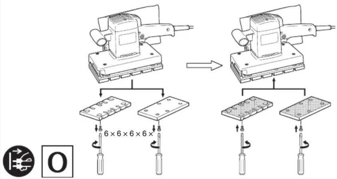
Replace the pad only. Use the other parts without removing them.
- Attaching Velcro Type Sanding Paper or Stick-on Type sanding Paper (optional accessories)
Match the sanding paper's hole with the pad's hole and strongly push the sanding paper with the palm of your hand to fasten it securely in place.
- RCD
The use of a residual current device with a rated residual current of 30 mA or less at all times is recommended.
SYMBOLS
WARNING.
The following show symbols used for the machine. Be sure that you understand their meaning before use.
 | SV12V / SV12SD : Orbital Sander |
 | To reduce the risk of injury, user must read instruction manual. |
 | Only for EU countriesDo not dispose of electric tools together with household waste material!In observance of European Directive 2012/19/EU on waste electrical and electronic equipment and its implementation in accordance with national law, electric tools that have reached the end of their life must be collected separately and returned to an environmentally compatible recycling facility. |
| V Rated voltage | |
| P Power input | |
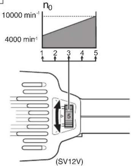
| n_0 | No-load speed |
 | Switching ON |
 | Switching OFF |
 | Disconnect mains plug from electrical outlet |
 | Class II tool |
STANDARD ACCESSORIES
In addition to the main unit (1 unit), the package contains the accessories listed in the below.
○ Sanding paper 1
○ Dust bag 1
Standard accessories are subject to change without notice.
APPLICATIONS
○ Finish polishing of woodwork surfaces
○ Sanding surfaces of woodwork or sheet metal prior to painting, etc.
SPECIFICATIONS
| Model | SV12V | SV12SD |
| Voltage (by areas)* | (110 V, 120 V, 220 V, 230 V, 240 V)~ | |
| Power Input 300 W | ||
| No-load speed | 4000 – 10000 min-1 | 10000 min-1 |
| Diam. of Orbit | 2.4 mm | |
| Sanding pad size | 114 mm × 228 mm | |
| Sanding paper size | 114 mm × 280 mm | |
| Weight (without cord)** | 2.9 kg | |
* Be sure to check the nameplate on product as it is subject to change by areas.
** According to EPTA-Procedure 01/2014
English
NOTE
Due to HiKOKI's continuing program of research and development, the specifications herein are subject to change without prior notice.
MOUNTING AND OPERATION
| Action Figure Page | ||
| Installing the sanding paper 1 59 | ||
| Attaching the dust bag 2 59 | ||
| Switching on and off 3 59 | ||
| Locking-on the on / off switch 4 59 | ||
| Releasing the on / off switch 5 59 | ||
| Adjusting speed (SV12V) 6 60 | ||
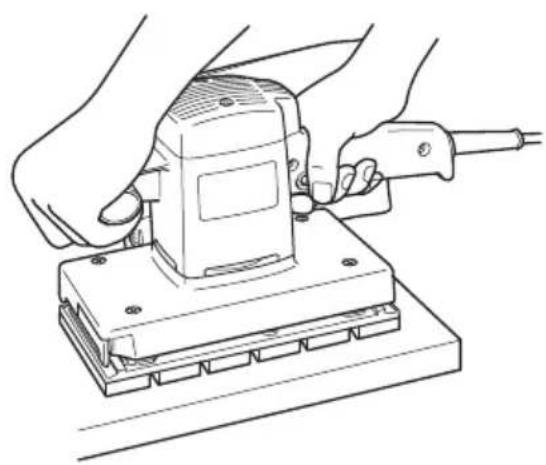
| How to hold the orbital sander 7 60 | ||
| Attaching magic pad(Optional accessories) | 8 | 60 |
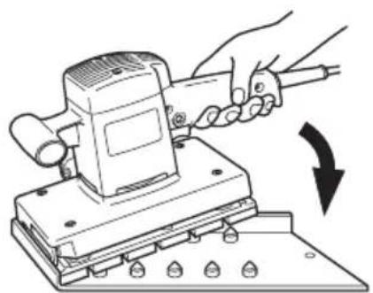
| Attaching cleaner adaptor(Optional accessories) | 9 | 60 |
| Making a hole in the sanding paper with the punch plate(optional accessories) | 10 60 | |
| Selecting accessories — 61 |
Attaching sanding paper (Fig. 1)
(Start at Switch handle's side)
(1) Open paper holder by turning the clamping lever.
(2) Insert the sanding paper between the paper holder and the bottom plate until it can go no further.
(3) Match the width of the sanding paper with the width of the pad.
Return the clamping lever to its original position to secure the sanding paper.
(4) When using perforated sanding paper.
To secure the other end of the sanding paper, pull the sanding paper while aligning the holes of the sanding paper with the holes of the pad.
(5) When using non-perforated sanding paper.
Align the sanding paper on the pad and pull the sanding paper to secure the other end.
CAUTION
○ After mounting the sanding paper, return the clamping lever to its original position.
☐ The sanding paper must be precisely attached on the pad, ensuring that there is ample tension (leaving no slack). Loosely attached sanding paper could result in unevenly sanded surfaces and/or damage to the sanding paper itself.
How to move the orbital sander
For optimum operating efficiency, alternately move the sander forward and backward at a constant speed and balance.
After installing new sanding paper
Movement of the sander may tend to become unsteady after new sanding paper has been installed, because of the new, coarse grain of the paper. This can be avoided by slightly tilting the sander forward or backward during sanding or polishing. Sander movement will become steady as the sanding paper surface becomes properly abraded.
SANDING PAD AND SANDING PAPER SELECTION
| Sanding pad | Sanding paper | ||||
| Type | Papar mounting | Code No. | Paper type | Grid No. | Code No. |
| Perforated felt pad | Spring clip | 300090 | Non-perforated | AA40 | 300054 |
| AA60 | 300055 | ||||
| AA80 | 300056 | ||||
| AA100 | 300057 | ||||
| AA120 | 300058 | ||||
| AA150 | 300059 | ||||
| AA180 | 300060 | ||||
| AA220 | 300061 | ||||
| AA240 | 300062 | ||||
| Perforated | AA40 | 300045 | |||
| AA60 | 300046 | ||||
| AA80 | 300047 | ||||
| AA100 | 300048 | ||||
| AA120 | 300049 | ||||
| AA150 | 300050 | ||||
| AA180 | 300051 | ||||
| AA220 | 300052 | ||||
| AA240 | 300053 | ||||
| Perforated magic pad | Presser sensitive 300081 | Non-perforated magic | AA40 300072 |
| AA60 300073 | |||
| AA80 300074 | |||
| AA100 300075 | |||
| AA120 300076 | |||
| AA150 300077 | |||
| AA180 300078 | |||
| AA220 300079 | |||
| AA240 300080 | |||
| Perforated magic | AA40 300068 | ||
| AA60 300064 | |||
| AA80 300065 | |||
| AA100 300066 | |||
| AA120 300067 | |||
| AA150 300068 | |||
| AA180 300069 | |||
| AA220 300070 | |||
| AA240 300071 |
MAINTENANCE AND INSPECTION
1. Emptying and cleaning the Dust Bag
If the dust bag contains too much saw dust, dust collection will be affected. Empty the dust bag when it gets full.
Remove the dust bag, open the fastener, and dispose of the contents.
2. Inspecting the sanding paper
Since use of worn-out sanding paper will degrade efficiency and cause possible damage to the pad, replace the sanding paper as soon as excessive abrasion is noted.
3. Inspecting the mounting screws
Regularly inspect all mounting screws and ensure that they are properly tightened. Should any of the screws be loose, retighten them immediately. Failure to do so could result in serious hazard.
4. Inspecting the carbon brushes
For your continued safety and electrical shock protection, carbon brush inspection and replacement on this tool should ONLY be performed by a HiKOKI AUTHORIZED SERVICE CENTER.
5. Maintenance of the motor
The motor unit winding is the very "heart" of the power tool. Exercise due care to ensure the winding does not become damaged and/or wet with oil or water.
CAUTION
In the operation and maintenance of power tools, the safety regulations and standards prescribed in each country must be observed.
GUARANTEE
We guarantee HiKOKI power tools in accordance with statutory/country specific regulation. This guarantee does not cover defects or damage due to misuse, abuse, or normal wear and tear. In case of complaint, please send the power tool, undismantled, with the GUARANTEE CERTIFICATE found at the end of this Handling instruction, to a HiKOKI Authorized Service Center.
IMPORTANT
Correct connection of the plug
The wires of the main lead are coloured in accordance with the following code:
Blue: — Neutral
Brown: — Live
As the colours of the wires in the main lead of this tool may not correspond with the coloured markings identifying the terminals in your plug proceed as follows:
The wire coloured blue must be connected to the terminal marked with the letter N or coloured black. The wire coloured brown must be connected to the terminal marked with the letter L or coloured red. Neither core must be connected to the each terminal.
NOTE:
This requirement is provided according to BRITISH STANDARD 2769: 1984.
Therefore, the letter code and colour code may not be applicable to other markets except The United Kingdom.
Information concerning airborne noise and vibration
The measured values were determined according to EN62841 and declared in accordance with ISO 4871.
Measured A-weighted sound power level: 82 dB (A).
Measured A-weighted sound pressure level: 71 dB (A).
Uncertainty K: 3 dB (A).
Wear hearing protection.
Vibration total values (triax vector sum) determined according to EN62841.
Sanding:
Vibration emission value a_h=5.9 m/s^2
Uncertainty K = 1.5 m/s²
English
The declared vibration total value has been measured in accordance with a standard test method and may be used for comparing one tool with another.
It may also be used in a preliminary assessment of exposure.
WARNING
☐ The vibration emission during actual use of the power tool can differ from the declared total value depending in the ways in which the tool is used.
- Identify safety measures to protect the operator that are based on an estimation of exposure in the actual conditions of use (taking account of all parts of the operating cycle such as the times when the tool is switched off and when it is running idle in addition to the trigger time).
NOTE
Due to HiKOKI's continuing program of research and development, the specifications herein are subject to change without prior notice.
VEILIGHEIDSWAARSCHUWINGEN
VEDLIKEHOLD OG INSPEKSJON
hiemaiyota © Hiekrapaperi 1
○ Pölypussi ....1
flowchart
graph TD
    A["Initial Component"] --> B["Assembly Step"]
    B --> C["Disassembly Step"]
    C --> D["Final Assembly"]

    subgraph Initial Components
        E["Component 1: Left Side"]
        F["Component 2: Right Side"]
    end

    subgraph Final Assembly
        G["Final Component"]
        H["Final Assembly"]
    end

    I["Diagram 1: Internal Components"]
    J["Diagram 2: Internal Components"]
    K["Diagram 3: Internal Components"]
    L["Diagram 4: Internal Components"]
    M["Diagram 5: Internal Components"]
    N["Diagram 6: Internal Components"]
    O["Diagram 7: Internal Components"]
    P["Diagram 8: Internal Components"]
    Q["Diagram 9: Internal Components"]
    R["Diagram 10: Internal Components"]
2
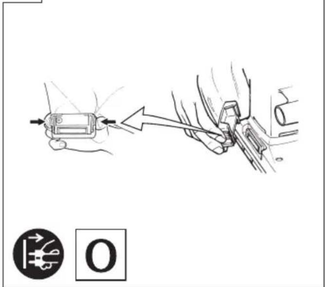
text_image
Diagram showing a hand holding a device connected to a car's seatbelt, with an arrow indicating the process and a circular icon labeled 'O' below.4
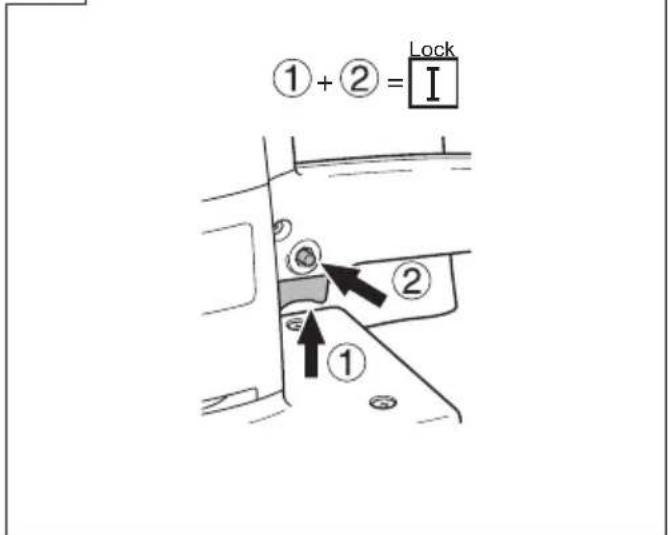
text_image
① + ② = Lock I ① ②3
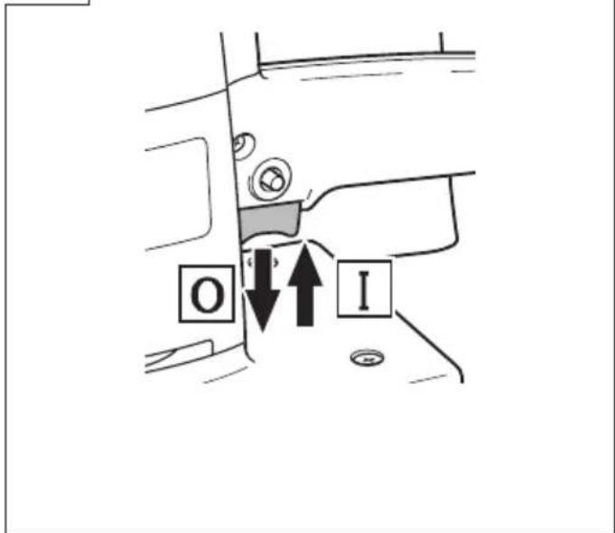
text_image
O I5
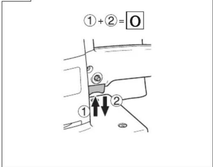
text_image
① + ② = O ① ↑ ↓ ②6
text_image
n₀ 10000 min⁻¹ 4000 min⁻¹ 1 2 3 4 5 (SV12V)7
natural_image
Line drawing of hands operating a power tool on a workbench (no text or symbols)8
text_image
Diagram illustrating the process of a mechanical device being switched to a multi-pin plate, with tool positioning and screwdriver arrangement indicated.9

natural_image
Line drawing of a mechanical power tool with attached housing and pipes (no text or symbols)

10
natural_image
Illustration of a hand using a power tool to press or install a machine component, with no visible text or symbols.

natural_image
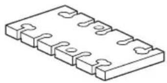
Isometric line drawing of a rectangular electronic component with multiple slots and mounting holes (no text or symbols)114 × 228 mm
natural_image
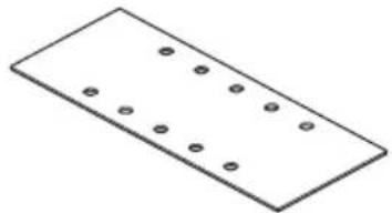
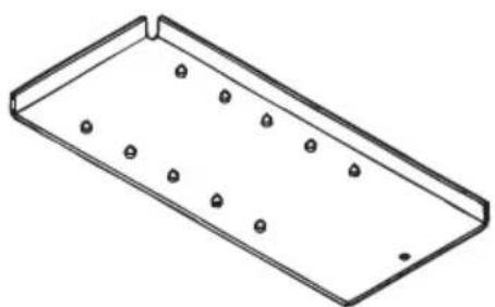
Simple 3D rectangular plate with evenly spaced circular holes (no text or symbols)114 × 280 mm
natural_image
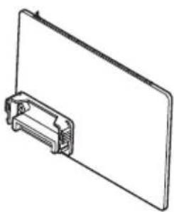
Line drawing of a clipboard with a plastic clip attached (no text or symbols)300177
natural_image
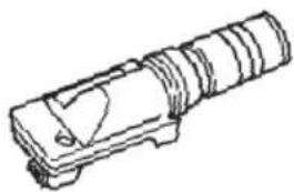
Technical line drawing of a mechanical component with no visible text or symbols300082
natural_image
Isometric line drawing of a rectangular metal tray with evenly spaced small holes (no text or symbols)301953

natural_image
Line drawing of a quill pen with inkwell (no text or symbols)| English | Português | ||
| GUARANTEE CERTIFICATE1 Model No.2 Serial No.3 Date of Purchase4 Customer Name and Address5 Dealer Name and Address(Please stamp dealer name and address) | CERTIFICADO DE GARANTIA1 Número do modelo2 Número do série3 Data de compra4 Nome e morada do cliente5 Nome e morada do distribuidor(Por favor, carimbe o nome e morada do distribuidor) | ||
| Deutsch Svenska | |||
| GARANTIESCHEIN1 Modell-Nr.2 Serien-Nr.3 Kaufdatum4 Name und Anschrift des Kunden5 Name und Anschrift des Händlers(Bitte mit Namen und Anschrift des Handlers abstempeln) | GARANTICERTIFIKAT1 Modellnr2 Serienr3 Inköpsdatum4 Kundens namn och adress5 Försäljarens namn och adress(Stämpla försäljarens namn och adress) | ||
| Français Dansk | |||
| CERTIFICAT DE GARANTIE1 No. de modèle2 No de série3 Date d’achat4 Nom et adresse du client5 Nom et adresse du revendeur(Cachet portant le nom et l’adresse du revendeur) | GARANTIBEVIS1 Modelnummer2 Serienummer3 Købsdato4 Kundes navn og adresse5 Forhandlers navn og adresse(Indsæt stempel med forhandlers navn og adresse) | ||
| Italiano Norsk | |||
| CERTIFICATO DI GARANZIA1 Modello2 N° di serie3 Data di acquisto4 Nome e indirizzo dell’acquirente5 Nome e indirizzo del rivenditore(Si prega di apporre il timbro con questi dati) | GARANTISERTIFIKAT1 Modellnr.2 Serienr.3 Kjøpsdato4 Kundens navn og adresse5 Forhandlerens navn og adresse(Vennligst stemple forhandlerens navn og adresse) | ||
| Nederlands Suomi | |||
| GARANTIEBEWIJS1 Modelnummer2 Serienummer3 Datum van aankoop4 Naam en adres van de gebruiker5 Naam en adres van de handelaar(Stempel a.u.b. naam en adres vande de handelaar) | TAKUUTODISTUS1 Malli nro2 Sarja nro3 Ostopäivämäärä4 Asiakkaan nimi ja osoite5 Myyjän nimi ja osoite(Leimaa myyjän nimi ja osoite) | ||
| Español | Ελληνικά | ||
| CERTIFICADO DE GARANTÍA1 Número de modelo2 Número de serie3 Fecha de adquisición4 Nombre y dirección del cliente5 Nombre y dirección del distribudor(Se ruega poner el sello del distribudor con su nombre y dirección) | ΠΙΣΤΟΠΟΙΗΤΙΚΟ ΕΓΓΥΗΣΗΣ1 Ap. Movτέλου2 Aùξων Ap.3 Ημερομηνία αγοράς4 ’Ονομα και διεύθυνση πελάτη5 ’Ονομα και διεύθυνση μεταπωλητή(Παρακαλούμε να χρησιμοποιηθεί σφραγίδα) | ||
HiKOKI
| 1 | |
| 2 | |
| 3 | |
| 4 | |
| 5 |
Siemensring 34, 47877 willich, Germany
Tel: +49 2154 49930
Fax: +49 2154 499350
URL: http://www.hikoki-powertools.de
Hikoki Power Tools Netherlands B.V.
Brabanthaven 11, 3433 PJ Nieuwegein, The Netherlands
Tel: +31 30 6084040
Fax: +31 30 6067266
URL: http://www.hikoki-powertools.nl
Hikoki Power Tools (U.K.) Ltd.
Precedent Drive, Rooksley, Milton Keynes, MK 13, 8PJ,
United Kingdom
Tel: +44 1908 660663
Fax: +44 1908 606642
URL: http://www.hikoki-powertools.uk
Hikoki Power Tools France S.A.S.
Hikoki Power Tools Belgium N.V./S.A.
Koningin Astridlaan 51, B-1780 Wemmel, Belgium
Tel: +32 2 460 1720
Fax: +32 2 460 2542
URL http://www.hikoki-powertools.be
Hikoki Power Tools Italia S.p.A
Via Piave 35, 36077, Altavilla Vicentina (VI), Italy
Tel: +39 0444 548111
Fax: +39 0444 548110
URL: http://www.hikoki-powertools.it
Hikoki Power Tools Ibérica, S.A.
C/ Puigbarral, 26-28, Pol. Ind. Can Petit, 08227 Terrassa
(Barcelona), Spain
Tel: +34 93 735 6722
Fax: +34 93 735 7442
URL: http://www.hikoki-powertools.es
Kjeller Vest 7, N-2007 Kjeller, Norway
Tel: (+47) 6692 6600
Fax: (+47) 6692 6650
URL: http://www.hikoki-powertools.no
Hikoki Power Tools Sweden AB
Rotebergsvagen 2B SE-192 78 Sollentuna, Sweden
Tel: (+46) 8 598 999 00
Fax: (+46) 8 598 999 40
URL: http://www.hikoki-powertools.se
Hikoki Power Tools Denmark A/S
Lillebaeltsvej 90, 6715 Esbjerg N, Denmark
Tel: (+45) 75 14 32 00
Fax: (+45) 75 14 36 66
URL: http://www.hikoki-powertools.dk
Hikoki Power Tools Finland Oy
Tupalankatu 9, 15680 Lahti, Finland
Tel: (+358) 20 7431 530
Fax: (+358) 20 7431 531
URL: http://www.hikoki-powertools.fi
natural_image
Line drawing of a quill pen with inkwell (no text or symbols)| English Italia no | ||
| EC DECLARATION OF CONFORMITYWe declare under our sole responsibility that Orbital Sander, identified by type and specific identification code *1), is in conformity with all relevant requirements of the directives *2) and standards *3). Technical file at *4) - See below.The European Standard Manager at the representative office in Europe is authorized to compile the technical file.The declaration is applicable to the product affixed CE marking. | DICHIARAZIONE DI CONFORMITÀ CEDichiariamo sotto la nostra esclusiva responsabilità che la levigatrice orbitale, identificata dal tipo e dal codice identificativo specifico *1), è conforme a tutti i requisiti delle direttive *2) e degli standard *3Documentazione tecnica presso *4) - Vedere sotto.Il gestore delle norme europee presso l'ufficio di rappresentanza in Europa è autorizzato a compilare il fascicolo tecnico.La dichiarazione è applicabile ai prodotti cui sono applicati i marchi CE. | |
| Deutsch Nederlands | ||
| EG-KONFORMITÄTSERKLÄRUNGWir erklären in alleiniger Verantwortung, dass der durch den Typ und den spezifischen Identifizierungscode *1) identifizierte Schwingschleifer allen einschlägigen Bestimmungen der Richtlinien *2) und Normen *3) entspricht. Technische Unterlagen unter *4) - Siehe unten.Die Leitung der repräsentativen Behörde für europäische Normen und Richtlinien ist berechtigt, die technischen Unterlagen zusammenzustellen.Die Erklärung gilt für die an dem Produkt angebrachte CE-Kennzeichnung. | EC VERKLARING VAN CONFORMITEITWij verklaren onder onze eigen verantwoordelijkheid dat Vlakschuurmachine, geïdentificeerd door het type en de specifieke identificatiecode*1), voldoet aan alle relevante bepalingen van de richtlijnen*2) en normen*3). Technische documentatie bij*4) - zie onder.De Europese Normen Manager bij de vertegenwoordiging in Europa is gemachtigd om het technisch dossier samen te stellen.Deze verklaring is van toepassing op producten voorzien van de CE-markeringen. | |
| Français Español | ||
| DECLARATION DE CONFORMITE CENous déclarons sous notre entière responsabilité que la ponceuse orbitale, identifiée par le type et le code d'identification spécifique *1) est en conformité avec toutes les exigences applicables des directives *2) et des normes *3). Dossier technique en *4) - Voir ci-dessous.Le Gestionnaire des normes européennes du bureau de représentation en Europe est autorisé à constituer le dossier technique.Cette déclaration s'applique aux produits désignés CE. | DECLARACIÓN DE CONFORMIDAD DE LA CEDeclaramos bajo nuestra única responsabilidad que la Lijadora orbital, identificada por tipo y por código de identificación específico *1), está en conformidad con todas las disposiciones correspondientes de las directivas *2) y de las normas *3). Documentación técnica en *4) - Ver a continuación.El Director de Normas Europeas en la oficina de representación en Europa está autorizado para elaborar el expediente técnico.La declaración se aplica al producto con marcas de la CE. | |
| *1) SV12SD C350690SSV12V C350665S*2) 2006/42/EC, 2014/30/EU, 2011/65/EU*3) EN62841-1:2015EN62841-2-4:2014+AC:2015EN55014-1:2006+A1:2009+A2:2011EN55014-2:1997+A1:2001+A2:2008EN61000-3-2:2014EN61000-3-3:2013 | ||
| *4) Representative office in EuropeHikoki Power Tools Deutschland GmbHSiemensring 34, 47877 Willich, GermanyHead office in JapanKoki Holdings Co., Ltd.Shinagawa Intercity Tower A, 15-1, Konan 2-chome,Minato-ku, Tokyo, Japan | 28. 6. 2019Naoto YamashiroEuropean Standard Manager28. 6. 2019 A. NakagawaCorporate Officer A. NakagawaCorporate Officer | |
| Português Norsk | ||
| DECLARAÇÃO DE CONFORMIDADE CEDeclaramos, sob nossa única e inteira responsabilidade, que Lixadeira Orbital, identificada por tipo e código de identificação específico *1), está em conformidade com todos os requerimentos relevantes das diretivas *2) e normas *3). Ficheiro técnico em *4)-Consulte abaixo.O Gestor de Normas Europeias no escritório de representação na Europa está autorizado a compilar o ficheiro técnico.A declaração aplica-se aos produtos com marca CE. | EF'S ERKLÆRING OM OVERENSSTEMMELSEVi erklærer på eget ansvar at plansliper, identifisert etter type og spesifikk identifikasjonskode *1), er i samsvar med alle relevante krav i direktiver *2) og standarder *3). Teknisk fil under *4) - Se nedenfor.Styreren for europeiske standarder ved representantkontoret i Europa er autorisert til å kompilere den tekniske filen.Erklæringen gjelder for CE-merket på produktet. | |
| Svenska Suomi | ||
| EG-DEKLARATION BETRÄFFANDE LIKFORMIGHETVi förklarar på eget ansvar att denna slip- och polermaskin, identifierad enligt typ och sårskild identifikationskod *1), överensstämmer med alla relevanta krav i direktiven *2) och standarderna *3). Teknisk fil enligt *4) – Se nedan.Den europeiska standardansvariga på representationskontoret i Europa är auktoriserad att sammanställa den tekniska filen.Denna försäkran gäller för produkten med tillhörande CE-märkning. | EY-ILMOITUS YHDENMUKAISUUDESTAVakuutamme yksinomaisella vastuullamme, että värähtelevä tasohiomakone, joka identifioidaan tyypin ja erityisen tunnistuskoodin *1) perusteella, on kaikkien direktiivien *2) ja standardien *3) asiaankuuluvien vaatimusten mukainen. Tekninen tiedosto kohdassa *4) – katso alta.Eurooppalaisten standardien hallintaelin Euroopan edustustossa on valtuutettu kokoarnaan teknisen tiedoston.Ilmoitus on sovellettavissa tuotteeseen kiinnitettyyn CE-merkintään. | |
| Dansk Ελληνικά | ||
| EF-OVERENSSTEMMELSESERKLÆRINGVi erklærer os fuldstændigt ansvarlige for, at rystepudseren, identificeret ved type og specifik identifikationskode *1), er i overensstemmelse med alle relevante krav i direktiverne *2) og standarderne *3). Teknisk fil i *4) – Se nedenfor.Lederen af europæiske standarder på repräsentationskontoret i Europa er bemyndiget til at kompilere den tekniske fil.Erklæringen gælder produktet, der er mærket med CE. | ΕΚ ΔΗΛΟΣΗ ΕΝΑΡΜΟΝΙΣΜΟΥΔηλώνουμε με αποκλειστική μας ευθύνη ότι το Παλμικό τριβείο, το οποίο προσδιορίζεται από τον τύπο και ειδικό αναγνωριστικό κωδικό *1), είναι σύμφωνο με όλες τις σχετικές απαιτήσεις των Οδηγιών *2) και στα σχετικά πρότυπα *3). Τεχνικό Αρχείο στο *4) – Δείτε παρακάτω.Ο Διαχειριστής Ευρωπαϊκών Προτύπων στο γραφείο εκπροσώπησησ στην Ευρώπη είναι εξουσιοδοτημένος για τη σύνταξη του τεχνικού φακέλου.Η δήλωση ισχύει μόνο για το προϊόν που είναι τοποθετημένη σήμανση CE. | |
| *1) SV12SD C350690SSV12V C350665S*2) 2006/42/EC, 2014/30/EU, 2011/65/EU*3) EN62841-1:2015EN62841-2-4:2014+AC:2015EN55014-1:2006+A1:2009+A2:2011EN55014-2:1997+A1:2001+A2:2008EN61000-3-2:2014EN61000-3-3:2013 | ||
| *4) Representative office in EuropeHikoki Power Tools Deutschland GmbHSiemensring 34, 47877 Willich, GermanyHead office in JapanKoki Holdings Co., Ltd.Shinagawa Intercity Tower A, 15-1, Konan 2-chome,Minato-ku, Tokyo, Japan | 28. 6. 2019Naoto YamashiroEuropean Standard Manager28. 6. 2019A. NakagawaCorporate Officer | |