
541EA - Drill HUSQVARNA - Free user manual and instructions
Find the device manual for free 541EA HUSQVARNA in PDF.
| Product type | Thermal ground drill (auger) |
| Brand | Husqvarna |
| Model | 541EA |
| Engine | G43L, 2-stroke, 41.5 cm³ |
| Rated power | 1.47 kW |
| Fuel tank | 0.94 L |
| Fuel mixture | Unleaded gasoline 90 RON min + 2-stroke oil, ratio 50:1 (2%) |
| Spark plug | NGK BPMR7A, gap 0.6-0.7 mm |
| Idle speed | 2500 ± 200 rpm |
| Maximum drill speed | 350 min⁻¹ (rpm) |
| Net weight | 9.7 kg |
| Gross weight | 11.8 kg |
| Dimensions (packaging) | 540 x 370 x 340 mm |
| Sound power level | 108.1 dB(A) |
| Sound pressure level | 101.0 dB(A) |
| Handlebar vibrations | 11.4 m/s² |
| Braking system | Safety brake by leg contact |
| Included accessories | Standard drill Ø200 mm double helix, keys, primer bulb |
| Optional accessories | Drills Ø80 mm single helix, Ø150 mm double helix, extensions L=600 and L=1000 mm |
| Maintenance | Regular cleaning of air filter, fuel filter, spark plug; drain fuel for long storage |
| Safety | Mandatory wearing of protections (eyes, hearing, head, gloves, shoes); safety distance 5 m |
| Reparability | Original Husqvarna spare parts; repairs by authorized center |
Frequently Asked Questions - 541EA HUSQVARNA
User questions about 541EA HUSQVARNA
0 question about this device. Answer the ones you know or ask your own.
Ask a new question about this device
Download the instructions for your Drill in PDF format for free! Find your manual 541EA - HUSQVARNA and take your electronic device back in hand. On this page are published all the documents necessary for the use of your device. 541EA by HUSQVARNA.
USER MANUAL 541EA HUSQVARNA
natural_image
Silhouette of a mechanical spring or drill bit with no text or symbols541EA
EN Operator's manual 2-16
Troubleshooting....13
Transportation and storage 14
Technical data 14
Accessories 15
Declaration of conformity....16
Introduction
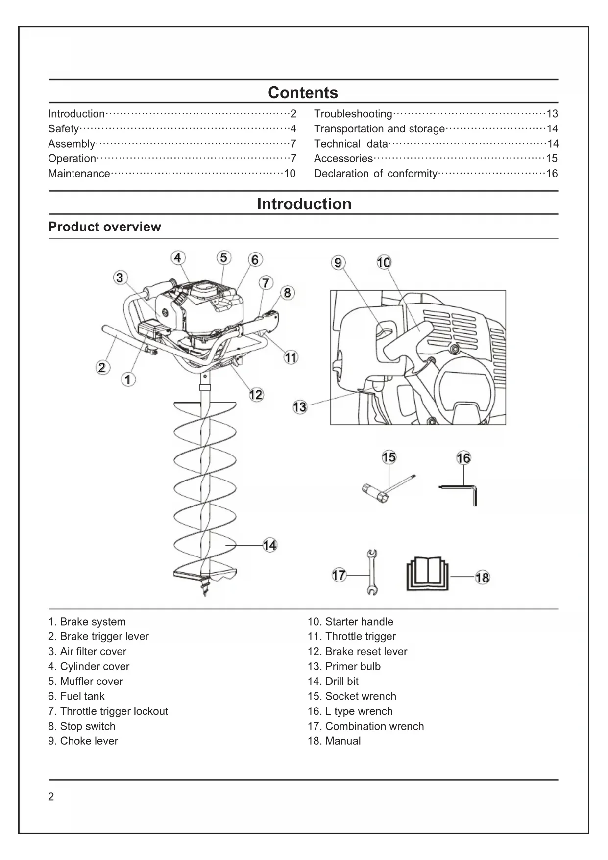
Product overview

-
Brake system
-
Brake trigger lever
-
Air filter cover
-
Cylinder cover
-
Muffler cover
-
Fuel tank
-
Throttle trigger lockout
-
Stop switch
-
Choke lever
-
Starter handle
-
Throttle trigger
-
Brake reset lever
-
Primer bulb
-
Drill bit
-
Socket wrench
-
L type wrench
-
Combination wrench
-
Manual
Symbols on the product

WARNING! An earth auger is a dangerous tool if used carelessly or incorrectly and can cause serious, even fatal injuries. It is extremely important that you read and understand the contents of this Operator's Manual.

Fire and sparks are strictly prohibited near the fuel.

No smoking near fuel.

Please read the operator's manual carefully and make sure you understand the instructions before using the machine.

Always wear:
• Approved hearing protection
- Approved eye protection
- Approved head protection

Always wear approved protective gloves.

Wear sturdy, non-slip boots or shoes.

Wear protective clothing during operation.

Caution for fire.

Keep away from hot parts of the machine (such as the muffler).

Prohibit the operator from leaning on the machine.

Do not touch the rotating drill bit when the machine is running.

Keep away from underground pipes and wires, it is forbidden for drills to damage underground pipes and wires.

The direction of the arrow indicates the normal working direction of the drill.
Product liability
As referred to in the product liability laws, we are not liable for damages that our product causes if:
• the product is incorrectly repaired.
- the product is repaired with parts that are not from the manufacturer or not approved by the manufacturer.
- the product has an accessory that is not from the manufacturer or not approved by the manufacturer.
- the product is not repaired at an approved service center or by an approved authority.
Safety
Safety definitions
The definitions below give the level of severity for each signal word.

WARNING: Injury to persons.

CAUTION: Damage to the product.
Note: This information makes the product easier to use.
General safety instructions

WARNING: Read the warning instructions that follow before you use the product.
- Use the product correctly. Injury or death is a possible result of incorrect use. Only use the product for the tasks found in this manual. Do not use the product for other tasks.
- Obey the instructions in this manual. Obey the safety symbols and the safety instructions. If the operator does not obey the instructions and the symbols, injury, damage or death is a possible result.
- Do not discard this manual. Use the instructions to assemble, to operate and to keep your product in good condition. Use the instructions for correct installation of attachments and accessories. Only use attachment and accessories which are same as original ones or supplied by Husqvarna or our representative.
- This manual cannot include all situations that can occur when you use the product. Be careful and use your common sense. Do not operate the product or do maintenance on the product if you are not sure about the situation. Speak to a product expert, your dealer, service agent or approved service center for information.
- Never use the machine if you are tired, if you have drunk alcohol, or if you are taking medication that could affect your vision, your judgement or your co-ordination.
- Wear personal protective equipment. See instructions under the Personal protective equipment heading.
- Never use a machine that is faulty. Carry out the safety checks, maintenance and service instructions described in this manual. Some maintenance and service measures must be carried out by trained and qualified specialists. See instructions under
the Maintenance heading.
- All covers and guards must be fitted before starting. Ensure that the spark plug cap and ignition lead are undamaged to avoid the risk of electric shock.
- Ensure that no-one comes closer than 5 m while you are working.
- Carry out an overall inspection of the machine before use. See the Maintenance schedule.
- When you use this product the engine makes an electromagnetic field. The electromagnetic field can cause damage to medical implants. Speak to your physician and medical implant manufacturer before you operate the product.
- Do not start the product indoors or near flammable material. The exhaust fumes are hot and can contain a spark which can start a fire.
- Running an engine in a confined or badly ventilated area can result in death due to asphyxiation or carbon monoxide poisoning.
- Do not let a child operate the product. Do not let a person without knowledge of the instructions operate the product.
- Make sure that you always monitor a person, with decreased physical capacity or mental capacity, that uses the product. A responsible adult must be there at all times.
Safety instructions for operation
- An earth auger is a dangerous tool if used carelessly or incorrectly and can cause serious, even fatal injuries. It is extremely important that you read and understand the contents of this Operator's Manual.
- Do not operate the product if there are persons or animals in the work area. Stop the product if a person or an animal goes into the work area. Do not turn with the product before you make sure that no persons or animals are in the safety area.
- Make sure that you are always in control of the product.
- Do not use the product if you cannot receive aid if an accident occurs. Always make sure others know you will operate the product before you start to operate the product.
- Remove all unwanted materials from the work area before you start. If the drilling attachment hits an object, the object can eject and cause injury or damage. Unwanted material can wind around the drilling attachment and cause damage.
- Do not use the product in bad weather (fog, rain, strong winds, risk of lightning or other weather conditions.). Dangerous conditions (such as slippery surfaces) can occur because of bad weather.
Personal protective equipment

WARNING: Read the warning instructions that follow before you use the product.
- Always use correct personal protective equipment when you operate the product. The personal protective equipment does not erase the risk of injury. The personal protective equipment decreases the grade of injury if an accident occurs. Ask the approved dealer for help in choosing the right equipment.
• Always use an approved eye protection while you operate the product. - Do not operate the product with bare feet or with open shoes. Always use heavy-duty slip-resistant boots.
- Use heavy, long pants.
- If it is necessary, use approved protective gloves.
- Use a helmet if it is possible that objects fall on your head.
• Always use approved ear protection while you operate the product. Noise for a long period can cause noise-induced hearing loss.
• Make sure that you have a first aid kit nearby.
Protective devices on the product
• Make sure that you regularly do the maintenance to the product.
• The life of the product increases.
• The risk of accidents decreases.
- Let an approved dealer or an approved service center regularly examine the product to do adjustments or repairs.
- Do not use a product with damaged protective equipment. If the product is damaged, speak to an approved service center.
Throttle trigger lockout

- Make sure that the throttle trigger (B) is locked at idle when you release the throttle trigger lockout (A).
- Push the throttle trigger lockout (A) and make sure that it goes back to its initial position when you release it.
- Push the throttle trigger (B) and make sure that it goes back to its initial position when you release it. Start the engine, and then apply full throttle. Release the throttle trigger (B) and examine if the drill attachment stops. If the drill attachment turns with the throttle in the idle position, examine the idle adjustment screw of the carburetor.
Stop switch
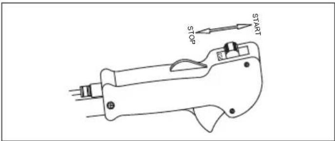
Start the engine. Make sure that the engine stops when you move the stop switch to the stop position.
Brake system
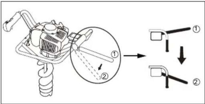
- If the drill bit stuck in operation, the brake leaver will hit the operator's leg, turning from working position ① to braking position ②. The brake system is activated and the machine stops.
- The operator's right hand leaves the control handle, and then holds the brake reset lever with the right hand, and the brake lever will automatically rebound from the braking position ② to the working position ①.
- After the brake lever is reset, press the throttle trigger and the machine will run normally.
Muffler
The muffler keeps the noise level to a minimum and keeps exhaust fumes away from the operator.

natural_image
Technical line drawing of a mechanical housing or enclosure component (no text or symbols)- Do not use an engine with a damaged muffler. A damaged muffler increases the noise level and the risk of fire. Keep a fire extinguisher near.
- Examine regularly that the muffler is attached to the product.
- Do not touch the engine or the muffler when the engine is on. Do not touch the engine or the muffler for a while after the engine stops. Hot surfaces can cause injuries.
- A hot muffler can cause a fire. Be careful, if you use the product near flammable liquids or fumes.
- Do not touch the parts in the muffler, if the muffler is damaged. The parts can contain some carcinogenic chemicals.
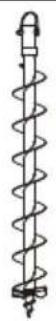
Drill

natural_image
Line drawing of a helical spring with a central pin (no text or symbols)Check the drill
- Never use drill that is blunt, cracked or damaged.
- Ensure that the drill is securely attached.
- When the blade is manufactured it is sharpened using an advanced method. This means that the blade cannot be re-sharpened using conventional methods. Worn blades must be replaced with new ones to ensure your machine works satisfactorily.
Fuel safety
- Do not start the product if there is fuel or engine oil on the product. Remove the unwanted fuel/oil and let the product dry. Remove unwanted fuel from the product.
- If you spill fuel on your clothing, change clothing immediately.
- Do not get fuel on your body, it can cause injury. If you get fuel on your body, use a soap and water to remove the fuel.
- Do not start the engine if you spill oil or fuel on the product or on your body.
- Do not start the product if the engine has a leak. Examine the engine for leaks regularly.
- Be careful with fuel. Fuel is flammable and the fumes are explosive and can cause injuries or death.
- Do not breathe in the fuel fumes, it can cause injury. Make sure that there is sufficient airflow.
- Do not smoke near the fuel or the engine.
- Do not put warm objects near the fuel or the engine.
- Do not add the fuel when the engine is on.
- Make sure that the engine is cool before you refuel.
- Before you refuel, open the fuel tank cap slowly and release the pressure carefully.
- Do not add fuel to the engine in an indoor area. Not sufficient airflow can cause injury or death because of asphyxiation or carbon monoxide.
- Tighten the fuel tank cap carefully or a fire can occur.
- Move the product at a minimum of 3 m (10 ft) from the position where you filled the tank before a start.
- Do not put too much fuel in the fuel tank.
- Make sure that a leak cannot occur when you move the product or fuel container.
- Do not put the product or a fuel container where there is an open flame, spark or pilot light. Make sure that the storage area does not contain an open flame.
- Only use approved containers when you move the fuel or put the fuel into storage.
- Empty the fuel tank before long-term storage. Obey the local law on where to dispose fuel.
- Clean the product before long-term storage.
- Remove the spark plug cable before you put the product into storage to make sure that the engine does not start accidentally.
Safety instructions for maintenance
- If you cannot adjust the idle speed to make the drill attachment stop, speak to your service center. Do not use the product until the product is correctly adjusted or repaired.
Assembly
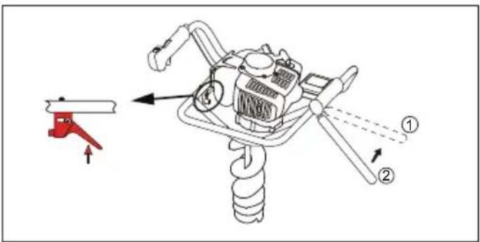
To assemble the brake

natural_image
Line drawing of a hand operating a mechanical tool with a rotating lever (no text or symbols)Insert the threaded end of the brake trigger lever into the hole under the brake system, and tighten the locknut.
To assemble the drill

- Disassembly the connecting pin (C) from the drill bit (B), and connect the transmission output shaft (A) with the drill bit (B).
- Insert the connecting pin (C) into the connecting hole of the drill bit (B), and then lock it with elastic steel wire (D) to ensure that the connecting pin (C) will not fall off.
Operation

WARNING: Read and understand the safety chapter before you operate the product.
Fuel
To use fuel

CAUTION: This product has a two-stroke engine. Use a mixture of gasoline and two-stroke engine oil. Make sure to use the correct quantity of oil in the mixture. Incorrect ratio of gasoline and oil can cause damage to the engine.
Gasoline

CAUTION: Do not use gasoline with an octane number less than 90 RON (87 AKI). This can cause damage to the product.

CAUTION: Do not use gasoline with more than 27% ethanol concentration (E27). This can cause damage to the product.

CAUTION: Do not use leaded gasoline. This can cause damage to the product.
• Always use new unleaded gasoline with a minimum octane number of 90 RON (87 AKI) and with less than 27% ethanol concentration (E27).
- Use gasoline with a higher octane number if you frequently use the product at continuously high engine speed.
- Always use a good quality unleaded gasoline/oil mixture.
Two-stroke engine oil
- Use only the two-stroke engine oil of high quality, especially HUSQVARNA two-stroke oil. Use only the oil of an air cooled engine.
- Mixture ratio 50:1 (2%).
- Oil of low quality and high oil/fuel ratio can decrease the lifetime of catalytic converters.
- Speak to your dealer when you select an oil.
- If Husqvarna two-stroke oil is not available, you can use another two-stroke oil of good quality that is intended for air cooled engines. Contact your dealer when you select oil.
- Do not use the two-stroke oil for water-cooled outboard engines. The two-stroke oil is sometimes referred to as outboard oil.
| Gasoline,liter | Oil,liter |
| 2%(50:1) | |
| 5 | 0.1 |
| 10 | 0.2 |
| 15 | 0.3 |
| 20 | 0.4 |
To make the fuel mixture
- Always use a clean fuel container when you mix the fuel.
- Do not make more than 30 days quantity of fuel mixture.
-
If the machine is not used for some time the fuel tank should be emptied and cleaned.
-
Add half of the gasoline quantity.
-
Add the full quantity of oil.
-
Shake the fuel mixture to mix the contents.
-
Add the remaining gasoline quantity.
-
Shake the fuel mixture to mix the contents.
-
Fill the fuel tank.
To add fuel

WARNING: Do not smoke or put hot objects near fuel. Before you add fuel, stop the engine and let it cool for minutes.

WARNING: When you add fuel, open the fuel tank cap slowly so that any excess pressure is released gently.

WARNING: After you add fuel, tighten the fuel tank cap carefully. Move the machine away from the refuelling area and the power before you start the engine.
• Always use a fuel container with an anti-spill valve.
- Clean the area around the fuel cap. Contamination in the tank can cause operating problems.
- Ensure that the fuel is well mixed by shaking the container before filling the tank.
To start and stop
To examine before start
- Check the drills. Never use drills that are blunt, cracked or damaged.
- Check that the machine is in perfect working order. Check that all nuts and screws are tight.
-
Check that the drill attachment always stops when the engine is idling.
-
Only use the machine for the purpose it was intended for.
- Make sure that the handle and safety features are in good working order. Never use a machine that lacks a part or has been modified outside its specifications.
- All covers must be correctly fitted and undamaged before you start the machine.
To start a cold engine

WARNING: Install the drill bit before starting the product.

WARNING: Move the product away from the refuelling area and the power. Put it on a flat surface. Make sure that no objects touch the drill attachment.

WARNING: Make sure that no unauthorised persons are in the work area. Or it can cause a risk of dangerous injury. The safety distance is 5 m.
- Put the stop switch to the start position.
- Put the brake trigger lever in the brake position before starting the machine.
- Press the air purge ten times.
- Move choke control to the choke position.
- Hold the product to the ground. Pull out the cord slowly with your right hand until you feel some resistance. Pull the cord quickly and with force. Keep doing it until you hear the engine start.
Note: Do not twist the starter rope around your hand.

CAUTION: Do not pull all the starter rope out. Hold the starter rope handle when it is fully extended. Failure to obey these instructions can cause damage to the engine.
- Set the choke control to the run position, then pull the start rope until the engine starts.
- Pull the throttle trigger lightly and run at low speed for 60 seconds.

WARNING: Do not touch the cover. It can burn your skin and cause electrical shock if the spark plug cap is damaged. Do not use a product with damaged spark plug cap.
To start a warm engine
- Put the stop switch to the start position.
- Put the brake trigger lever in the brake position before starting the machine.
- Press the air purge ten times.
- Set the choke control to the run position, then pull the start rope until the engine starts.
To stop
- Push the stop switch to stop the engine.
To drill
• The machine can cause serious personal injury. Read the safety instructions carefully. Learn how to use the machine.
- Do not touch the tool without first stop the engine.
• Never allow children to use the machine.
- Ensure that no-one comes closer than 5 m while you are working.
- Never allow anyone else to use the machine without first ensuring that they have read and understood the contents of the operator's manual.
• Always ensure you have a safe and stable working position.
• Always hold the machine with both hands.
- Use your right hand to control the throttle setting.
• Make sure that your hands and feet do not come near the drill attachment when the engine is running.
- Start drilling with half-throttle, and gradually increase the engine speed so that the drill may get into the ground smoothly.
• Always turn off the engine when you have finished drilling.
- If any foreign object is hit or if vibrations occur stop the machine immediately. Disconnect the spark plug cap from the spark plug. Check that the machine is not damaged. Repair any damage.
- Drilling into or contact with electrical cables or wires can lead to death or serious body injury. The machine is not electrically insulated. To reduce the risk of electrocution, always check for underground pipes, cables and wires before drilling. Contact your local utility company or locator service for information regarding cable and pipe locations. If necessary, confirm the actual locations by use of devices such as cable detectors and by carefully digging trenches.
- Striking something hard in the earth, such as rocks or tree roots, may cause the drill to come to a sudden stop. This can lead to a reacting motion on the auger. And the brake lever will touch the user's leg, then the drill will be stopped.
• Overexposure to vibration can lead to circulatory damage or nerve damage in people who have impaired circulation. Contact your doctor if you experience symptoms of overexposure to vibration. Such symptoms include numbness, loss of feeling, tingling, pricking, pain, loss of strength, changes in skin colour or condition. These symptoms normally appear in the fingers, hands or wrists. The risk increases at low temperatures.
- Make sure the drill attachment has stopped before cleaning, carrying out repairs or an inspection. Disconnect the spark plug cap from the spark plug.
- Always wear heavy gloves when replacing the drill bits.
- Use only original spare parts for repairs.
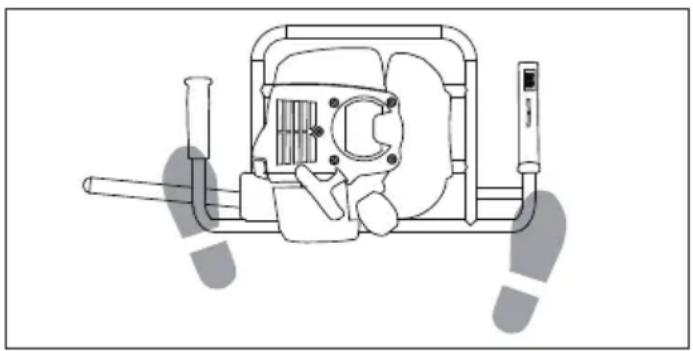
Drill operation
- The correct operating position is that the handle of the earth auger is lower than the waist, and the brake trigger

natural_image
Line drawing of a person using a mechanical device with a spring-like base (no text or symbols)- The relative position of the operator and the machine is shown in the figure below. Always hold the handle firmly with both hands during operation.
natural_image
Technical line drawing of a mechanical device with no visible text or symbolsMaintenance
Maintenance schedule
The following is a list of the maintenance steps that must be performed on the machine. Most of the items are described in the Maintenance section. The user must only carry out the maintenance and
service work described in this Operator's Manual. More extensive work must be carried out by an authorized service workshop.
| Daily Maintenance | maintenance | Weekly maintenance | Monthly maintenance |
| Clean the outside of the machine. X | |||
| Check the throttle and the throttle trigger. X | |||
| Check that the handle and the handlebar are undamaged and secured correctly. | X | ||
| Check that the stop switch works correctly. X | |||
| Check that the drill does not rotate at idle. X | |||
| Clean the air filter. Replace if necessary. X | |||
| Check the drill. Never use a drill that is blunt, cracked or damaged. | X | ||
| Check that nuts and screws are tight. X | |||
| Check that all cables and connections are correctly fixed | X | ||
| Check that there are no fuel leaks from the engine, tank and fuel lines. | X | ||
| Clean the dust and mud on the drill | X | ||
| Check the starter and starter cord. X | |||
| Make sure that the bevel gear is filled to 3/4 with grease. | X | ||
| Clean the spark plug. Remove the spark plug and do a check of the electrode gap. Adjust the electrode gap to 0.6-0.7mm, or replace the spark plug if it is necessary. Check the spark plug is fitted with a suppressor. | X | ||
| Maintenance | Daily maintenance | Weekly maintenance | Monthly maintenance |
| Clean the external surface of the carburetor and the area around it. | X | ||
| Clean the cooling system of the product. | X | ||
| Check the clutch, clutch springs and the clutch drum for wear. Replace if it is necessary. | X | ||
| Clean the muffler. | X | ||
| Replace the spark plug. Make sure that the spark plug is assembled with a suppressor. | X |
To adjust the carburetor
The basic carburetor settings are adjusted during testing at the factory. Adjustment must be carried out by a trained technician.
To check the muffler

WARNING: Do not use a product that has a defective muffler. Always replace a defective muffler.

WARNING: Risk of burn or fire. Mufflers with catalytic converters get very hot during operation.

WARNING: Risk of fire. The muffler decreases the noise level and identifies the exhaust gases from the operator. The exhaust gases are hot and can contain sparks.

CAUTION: The spark arrester screen must be replaced if it is damaged. Do not use a product if the spark arrester screen on the muffler is missing or defective.

CAUTION: If the spark arrester screen is blocked, the product will be too hot. This will cause damage to the cylinder and piston.
-
Make sure that the muffler is not damaged.
-
Make sure that the muffler is correctly attached to the product.
To check the air cleaner
- After every 25 hours of operation, please remove the air cleaner cover and inspect the air cleaner. If it is too dirty, wash it carefully in warm water containing a neutral detergent, and put it back to its original position after drying it thoroughly.
- If the air cleaner is distorted or damaged, please replace it with a new one.
- If the air cleaner is blocked, the efficiency of the engine will be reduced. In addition, the engine interior will suffer abnormal wear if it is operated without filter or if continually operated with a distorted or damaged filter.
To check the fuel filter
- After every 25 hours of operation, empty the fuel tank, detach the fuel filter from the tank, and remove all dirt. If the filter is too clogged, please replace it with a new one.
- If the fuel filter is clogged, the engine speed may be limited or speed fluctuations may occur.
- If the engine is operated without a fuel filter, dirt will accumulate in the carburetor and cause it to malfunction
To check the spark plug

CAUTION: Always use the recommended spark plug type. Incorrect spark plug type can cause damage to the product.
- The spark plug condition is influenced by: a) Incorrect carburettor adjustment. b) An incorrect fuel mixture (too much or incorrect type of oil). c) A dirty air filter.
- Do not touch the spark plug with your bare hands immediately after operation, as there is the risk of burns due to high temperature.
- If the machine is low on power, difficult to start or runs poorly at idle speed: always check the spark plug first before taking any further action.
- If the spark plug is dirty, clean it and check that the correct electrode gap is 0.6 to 0.7mm.
- The spark plug should be replaced after about a month in operation or earlier if necessary.
To adjust the idle speed
- Make sure that the air filter is clean. The drill attachment must not rotate in correct idle speed.
- Adjust the idle speed with the idle adjustment screw T which is identified with "T" mark.
- The idle speed is correct when the engine operates smoothly in all positions. The idle speed must be below the speed when the drill attachment starts to turn.

WARNING: If the idle speed cannot be adjusted so that the drill attachment stops, speak to the distributor or the service center. Do not use the product until it is correctly adjusted or repaired.
- Turn the idle adjustment screw clockwise until the drill attachment starts to turn.
- Turn the idle adjustment screw counterclockwise until the drill attachment stops.
To check the cooling system
The product has a cooling system to keep the work temperature low.

WARNING: Never touch the cylinder, muffler, or spark plug with your bare hands immediately after stopping the engine. The engine can become very hot when in operation, and doing so could result in severe burns.

WARNING: A dirty or blocked cooling system causes overheating. It causes damage to the piston and cylinder.
- When checking the product to make sure that it is in good condition before using it, check the area around the muffler and remove any staffs that attached, in case the muffler is overheated or even the engine catch on fire.
- Check the intake air cooling vent and the area around the cylinder cooling fins for blockage every 25 hours of use, in case of engine overheat or even product failure. Note that it is necessary to remove the upper cover and the lower cover in order to be able to view the upper part of the cylinder.
To check the gearbox
During normal use, disassembly the relief valve (A) every 50 hours to check whether there is still grease in the gearbox, and the grease in the gearbox must be replaced every 100 hours.

natural_image
Technical diagram of a mechanical assembly with labeled component A, showing components like bolts and tools (no text or symbols beyond label)Troubleshooting
| Starting failure | ||
| Check Possible cause Solution | ||
| Stop button Stop position Set the stop switch to the start position. | ||
| Starter pawls | Binding pawls | Adjust or replace the pawls. |
| Clean around the pawls. | ||
| Speak to an approved servicing dealer. | ||
| Fuel tank Incorrect fuel type. Drain it and use correct fuel. | ||
| Carburetor | Adjustment of the idle speed. | Adjust the idle speed with the T screw. |
| Spark (no spark) | Spark plug dirty or wet. | Make sure that the spark plug is dry and clean. |
| Spark plug clearance incorrect. | Clean the spark plug. Check that the electrode gap is correct. Make sure that the spark plug is installed with a suppressor. | |
| Refer to technical data for correct electrode gap. | ||
| Spark plug Spark plug loose. Tighten the spark plug. | ||
| Fuel filter Clogged fuel filter. Replace the fuel filter. | ||
| Engine starts but does not stay running | ||
| Fuel tank Incorrect fuel type. Drain it and use correct fuel. | ||
| Carburetor Engine will not idle correctly. Speak to your servicing dealer. | ||
| Air filter Clogged air filter. Clean the air filter. | ||
| Fuel filter Clogged fuel filter. Replace the fuel filter. | ||
| Abnormal noise in gearbox | ||
| Gear Gear worn Replacing related parts in the gearbox. | ||
| Grease Bad lubrication Add grease. | ||
Transportation and storage
- Store and transport the machine and fuel so that there is no risk of any leakage or fumes coming into contact with sparks or naked flames, for example, from electrical machinery, electric motors, electrical relays/ switches or boilers.
- When storing and transporting fuel always use approved containers intended for this purpose.
- When storing the machine for long periods the fuel tank must be emptied. Contact your local petrol station to find out where to dispose of excess fuel.
- Ensure the machine is cleaned and that a complete service is carried out before long-term storage.
-
Store the machine out of reach of children.
-
In order to prevent unintentional starting of the engine, the spark plug cap must always be removed during long-term storage, if the machine is not under close supervision and when performing all service measures
- Keep equipment safe during transportation to prevent damage and accidents.
- Keep the product and equipment in a dry and frost-proof area.
- Clean the product.
- Replace or repair damaged components.
- Use the correct protective cover on the product that does not keep moisture.
- Keep the product tightly attached during transport.
Technical data
| Model | 541EA |
| Engine | G43L |
| Engine Displacement | 41.5cc |
| Engine rated power | 1.47 kW |
| Spark plug model | NGK BPMR7A |
| Spark plug electrode gap | 0.6-0.7mm |
| Idle speed | 2500±200 r/min |
| Clutch speed | 3300±200 r/min |
| Rotation at rated power | 7000~7500rpm |
| Maximum rotation | 12000 rpm |
| Max speed (drill) | 350min -1 |
| Fuel tank capacity | 0.94L |
| Gross weight | 11.8 kg |
| Net weight | 9.7kg |
| Package dimensions | 540x370x340 mm |
| Sound power level, LWA | 108.1 dB(A) |
| Sound pressure level, LPA | 101.0 dB(A) |
| Vibration on handlebar | 11.4m/s 2 |
Note:
- Reported data for equivalent sound power level and sound pressure level for the product has a typical statistical dispersion (standard deviation) of 2.5 dB (A).
- Reported data for vibration level has a typical statistical dispersion (standard deviation) of 1.5 m/s2 .
Accessories
| Approved accessories | Accessory type | Accessory article no. |
| Standard drill bit | Φ200mm double helix | 537619101 |
| Optional drill bit | Φ80mm single helix | 537618901 |
| Φ150mm double helix | 537619001 | |
| Optional extension rod | L=600mm | 537629101 |
| L=1000mm | 537629102 |
Standard drill bit

Optional drill bit and extension rod


Declaration of conformity
EU Declaration of conformity
We, Husqvarna AB, SE-56182 Huskvarna, Sweden,
tel: +46-36-146500, declare on our sole responsibility that the product:
| Description | Earth Auger |
| Brand | Husqvarna |
| Type/Model | 541EA |
| Identification | Serial numbers dating from 2022 and onwards |
Complies fully with the following EU directives and regulations:
| Directive/Regulation | Description |
| 2006/42/EC | "relating to machinery" |
| 2014/30/EU | "relating to electromagnetic compatibility" |
And that the following standards and/or technical specifications are applied:
2PfG 2593/12.16, EN ISO 12100:2010, EN ISO 14982:2009
Huskvarna, 2022-09-30
Claes Losdal, R&D Manager
(Authorized representative for Husqvarna AB and responsible for technical documentation)
CE
Contenido
Introducción....17
Seguridad....19
Montaje 22
Funcionamiento……23
Mantenimiento....26
Resolución de problemas……29
natural_image
Technical line drawing of a mechanical housing or enclosure component (no text or symbols)natural_image
Line drawing of a spiral mechanical component with a looped shaft and base (no text or symbols)Compruebe la broca
natural_image
Line drawing of a hand operating a mechanical tool with a rotating lever (no text or symbols)natural_image
Line drawing of a person in protective gear holding a mechanical device with a spring (no text or symbols)natural_image
Technical line drawing of a mechanical device with no visible text or symbolsMantenimiento
natural_image
Diagram of a helical spring with a central pin and base, no text or symbols presentnatural_image
Four different types of spiral mechanical components shown in line drawings (no text or symbols)Claes Losdal, director de I+D
natural_image
Technical line drawing of a mechanical housing or enclosure component (no text or symbols)natural_image
Line drawing of a spiral mechanical component with a looped shaft and base (no text or symbols)natural_image
Line drawing of a hand operating a mechanical tool with a rotating lever (no text or symbols)natural_image
Line drawing of a person in protective gear holding a tool, with a spiral base (no text or symbols)natural_image
Technical line drawing of a mechanical device with no visible text or symbolsManutenção
natural_image
Technical diagram of a mechanical assembly with labeled component A (no text or symbols beyond label)Attention aux incendies

natural_image
Technical line drawing of a mechanical housing or enclosure component (no text or symbols)natural_image
Line drawing of a spiral mechanical component with a hook and base mount (no text or symbols)Vérifiez le foret
natural_image
Line drawing of a hand operating a mechanical tool with a rotating lever (no text or symbols)natural_image
Line drawing of a person in protective gear holding a tool, with a spiral tool inserted (no text or symbols)natural_image
Technical line drawing of a mechanical device with no visible text or symbolsMaintenance
Programme de maintenance
natural_image
Diagram of a helical spring with a central pin and base, no text or symbols presentnatural_image
Four different types of spiral mechanical components shown in line drawings (no text or symbols)-
Sistem brek
-
Tuas pencetus brek
-
Penutup penapis udara
-
Penutup silinder
-
Penutup peredam
-
Tangki bahan api
-
Kuncian pencetus pendikit
-
Suis berhenti
-
Tuas pencekik
-
Pemegang pemula
-
Pencetus pendikit
-
Tuas set semula brek
-
Mentol primer
-
Bit gerudi
-
Sepana soket
-
Sepana jenis L
-
Sepana gabungan
-
Manual
natural_image
Technical line drawing of a mechanical housing or enclosure component (no text or symbols)natural_image
Line drawing of a spiral mechanical component with a hook and base mount (no text or symbols)Periksa gerudi
natural_image
Line drawing of a hand operating a tool with a rotating blade (no text or symbols)natural_image
Line drawing of a person in protective gear holding a spring, no text or symbols presentnatural_image
Technical line drawing of a mechanical device with no visible text or symbolsPenyelenggaraan
Jadual penyelenggaraan
natural_image
Diagram of a helical spring with a central pin and base, no text or symbols presentnatural_image
Four different types of spiral mechanical components shown in line drawings (no text or symbols)Nội dung
Giới thiệu....80
An toàn 82
Lắp ráp 85
Vận hành 85
Bảo trì....88
Khắc phục sự cố……92
natural_image
Technical line drawing of a rectangular electronic device with mounting holes and a handle (no text or symbols)natural_image
Line drawing of a spiral mechanical component with a handle and base (no text or symbols)Kiểm tra mũi khoan
natural_image
Line drawing of a hand operating a mechanical tool with a rotating arrow (no text or symbols)natural_image
Line drawing of a person using a handheld device with a spiral spring (no text or symbols)natural_image
Technical line drawing of a mechanical pump or pump assembly (no text or symbols)Bảo trì
Lịch bảo trì
natural_image
Technical diagram of a mechanical assembly with labeled component A, showing internal components and tool path (no text or symbols beyond label)Khắc phục sự cố
natural_image
Technical line drawing of a mechanical housing or enclosure component (no text or symbols)natural_image
Line drawing of a helical spring with a central pin and base, no text or symbols presentตรวจสอบเช็คดอกสว่าน
natural_image
Line drawing of a manual tool with a hand operating a cylindrical tool (no text or symbols)natural_image
Line drawing of a person in protective gear holding a spring, no text or symbols presentnatural_image
Technical line drawing of a mechanical pump or pump assembly with no visible text or symbolsการบํารุงรักษา
ตารางการป่ารุงรักษา
natural_image
Technical diagram of a mechanical assembly with labeled component A, showing internal components and tool path (no text or symbols beyond label)การแก้ไขปัญหา
natural_image
Diagram of a helical spring with a central hub and base, no text or symbols presentnatural_image
Four different types of spiral mechanical components shown in line drawings (no text or symbols)المحتويات
natural_image
Line drawing of a soldering iron with a screwdriver inserted (no text or symbols)نظام الفرامل

natural_image
Technical line drawing of a rectangular electronic component with mounting holes and a handle (no text or symbols)natural_image
Line drawing of a helical spring with a hook and base (no text or symbols)تحفق من المثقب
natural_image
Line drawing of a manual tool in a mechanical assembly, showing a hand operating a cylindrical tool with a rotating arrow (no text or symbols)natural_image
Line drawing of a person using a handheld device with a spiral tool (no text or symbols)natural_image
Technical line drawing of a mechanical device with no visible text or symbolsل Coordف
• demands to describe something applied in the address of the country.
natural_image
Line drawing of a spiral mechanical component with a handle and base (no text or symbols)natural_image
Four different types of spiral mechanical components shown in line drawings (no text or symbols)目录
简介……123
安全须知……125
产品组装……128
产品操作……128
产品维护……131
故障排除……134
运输和存放……135
技术参数……135
配件……136
简介
概述

natural_image
Technical line drawing of a mechanical housing or enclosure with mounting holes and internal compartments (no text or symbols)natural_image
Line drawing of a helical spring with a handle and base (no text or symbols)检查钻头
natural_image
Line drawing of a hand using a tool to adjust a cylindrical object, no text or symbols presentnatural_image
Line drawing of a person in protective gear holding a spring, no text or symbols presentnatural_image
Technical line drawing of a mechanical device with no visible text or symbols产品维护
维护保养计划
natural_image
Diagram of a helical spring with a hook, no text or symbols present可选钻头和可选延长杆

natural_image
Four different types of spiral mechanical components shown in line drawings (no text or symbols)Содержание
Введение……137
Безопасность……139
Сборка....143
Эксплуатация……143
Обслуживание……147
natural_image
Technical line drawing of a mechanical housing or enclosure component (no text or symbols)natural_image
Line drawing of a helical spring with a central pin (no text or symbols)Проверьте сверло
natural_image
Line drawing of a hand using a tool to adjust a cylindrical object, no text or symbols presentnatural_image
Line drawing of a person using a handheld device with a spiral spring (no text or symbols)natural_image
Technical line drawing of a mechanical device with no visible text or symbolsОбслуживание
График обслуживания
natural_image
Diagram of a helical spring with a hook, no text or symbols presentnatural_image
Four different types of spiral mechanical components shown in line drawings (no text or symbols)3Mict
Вступ....153
Безпека……155
Збірка 159
Експлуатация……159
natural_image
Technical line drawing of a mechanical housing or enclosure component (no text or symbols)natural_image
Line drawing of a spiral mechanical component with a hook and base (no text or symbols)Перевірте бур
natural_image
Line drawing of a person using a mechanical device with a spring scale (no text or symbols)natural_image
Technical line drawing of a mechanical pump or pump assembly with no visible text or symbolsnatural_image
Technical diagram of a mechanical assembly with labeled component A, showing internal components and tool path (no text or symbols beyond label)natural_image
Diagram of a helical spring with a hook, no text or symbols presentnatural_image
Four different types of spiral mechanical components shown in line drawings (no text or symbols)Husqvarna®
www.husqvarnagroup.com
Original instructions
2022-10


- Introduction
- Product overview
- Symbols on the product
- Product liability
- Safety
- Safety definitions
- General safety instructions
- Safety instructions for operation
- Personal protective equipment
- Protective devices on the product
- Throttle trigger lockout
- Stop switch
- Brake system
- Muffler
- Drill
- Check the drill
- Fuel safety
- Safety instructions for maintenance
- Assembly
- Operation
- Fuel
- Gasoline
- Two-stroke engine oil
- To make the fuel mixture
- To add fuel
- To start and stop
- To examine before start
- To start a cold engine
- To start a warm engine
- To stop
- To drill
- Drill operation
- Maintenance
- Maintenance schedule
- To adjust the carburetor
- To check the muffler
- To check the air cleaner
- To check the fuel filter
- To check the spark plug
- To adjust the idle speed
- To check the cooling system
- To check the gearbox
- Transportation and storage
- Note:
- Accessories
- Standard drill bit
- Optional drill bit and extension rod
- Declaration of conformity
- EU Declaration of conformity
- Contenido
- Compruebe la broca
- Mantenimiento
- Manutenção
- Vérifiez le foret
- Programme de maintenance
- Periksa gerudi
- Penyelenggaraan
- Jadual penyelenggaraan
- Nội dung
- Kiểm tra mũi khoan
- Bảo trì
- Lịch bảo trì
- ตรวจสอบเช็คดอกสว่าน
- การบํารุงรักษา
- ตารางการป่ารุงรักษา
- المحتويات
- تحفق من المثقب
- ل Coordف
- 目录
- 简介
- 概述
- 检查钻头
- 产品维护
- 维护保养计划
- Содержание
- Проверьте сверло
- Обслуживание
- График обслуживания
- 3Mict
- Перевірте бур
- Husqvarna®
Brand : HUSQVARNA
Model : 541EA
Category : Drill