
DS 150 - Drill HUSQVARNA - Free user manual and instructions
Find the device manual for free DS 150 HUSQVARNA in PDF.
| Product type | Drilling stand (pillar drill) |
| Brand | HUSQVARNA |
| Model | DS 150 |
| Height | 862 mm |
| Width | 266 mm |
| Depth | 522 mm |
| Weight | 14 kg |
| Drilling stroke | 495 mm |
| Max. drilling diameter | 150 mm |
| Column tilt | 0 to 60° |
| Base plate material | Aluminum with integrated vacuum plate |
| Fixation types | Vacuum plate, expansion/anchor chuck, threaded rod |
| Included accessories | Hex key (3 mm, 4 mm), user manual |
| Optional accessories | Vacuum pump VP 200, gearbox, removable wheel kit |
| Intended use | Drilling in concrete, brick, stone (ceilings, walls, floors) |
| Required protective equipment | Helmet, ear protection, goggles/visor, respirator, gloves, fitted clothing, steel-toe boots |
| Routine maintenance | Cleaning with compressed air, lubrication of moving parts |
| Repairs | Entrust to an authorized repairer |
| Certification | Compliant with Machinery Directive 98/37/EC, harmonized standard SE-EN12348 |
Frequently Asked Questions - DS 150 HUSQVARNA
User questions about DS 150 HUSQVARNA
0 question about this device. Answer the ones you know or ask your own.
Ask a new question about this device
Download the instructions for your Drill in PDF format for free! Find your manual DS 150 - HUSQVARNA and take your electronic device back in hand. On this page are published all the documents necessary for the use of your device. DS 150 by HUSQVARNA.
USER MANUAL DS 150 HUSQVARNA
Please read the operator's manual carefully and make sure you understand the instructions before using the machine.

natural_image
Simple line drawing of a scooter inside a circle (no text or symbols)GB ES DE FR
Symbols on the machine:
WARNING! The machine can be a dangerous tool if used incorrectly or carelessly, which can cause serious or fatal injury to the operator or others.
Please read the operator's manual carefully and make sure you understand the instructions before using the machine.


Always wear:
• Approved protective helmet
• Approved hearing protection
• Protective goggles or a visor
- Breathing mask

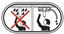
Ensure that water cannot leak into the machine when drilling in the ceiling. Use an appropriate water collector and cover the machine in plastic, but do not cover the air intakes and air outlets.
Other symbols/decals on the machine refer to special certification requirements for certain markets.
Symbols in the operator's manual:
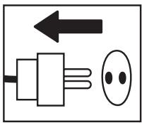
Inspection and/or maintenance should be carried out with the motor switched off and the plug disconnected.
Always wear approved protective gloves.
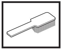
Regular cleaning is required.
Visual check.
Protective goggles or a visor must be worn.


CONTENTS
Contents
KEY TO SYMBOLS
Symbols on the machine: 2
Symbols in the operator's manual: 2
CONTENTS
Contents 3
WHAT IS WHAT?
What is what on the stand? 4
SAFETY INSTRUCTIONS
Steps before using a new stand 5
Personal protective equipment 5
General safety precautions 6
PRESENTATION
Stand DS 150 and DS 250 7
ASSEMBLY
Fit the wheel kit 8
Secure the stand 8
Assembly of drill motor 9
Adjust the column tilt 9
Drilling in the ceiling 9
MAINTENANCE
Stand maintenance 10
TECHNICAL DATA
EC-declaration of conformity 11
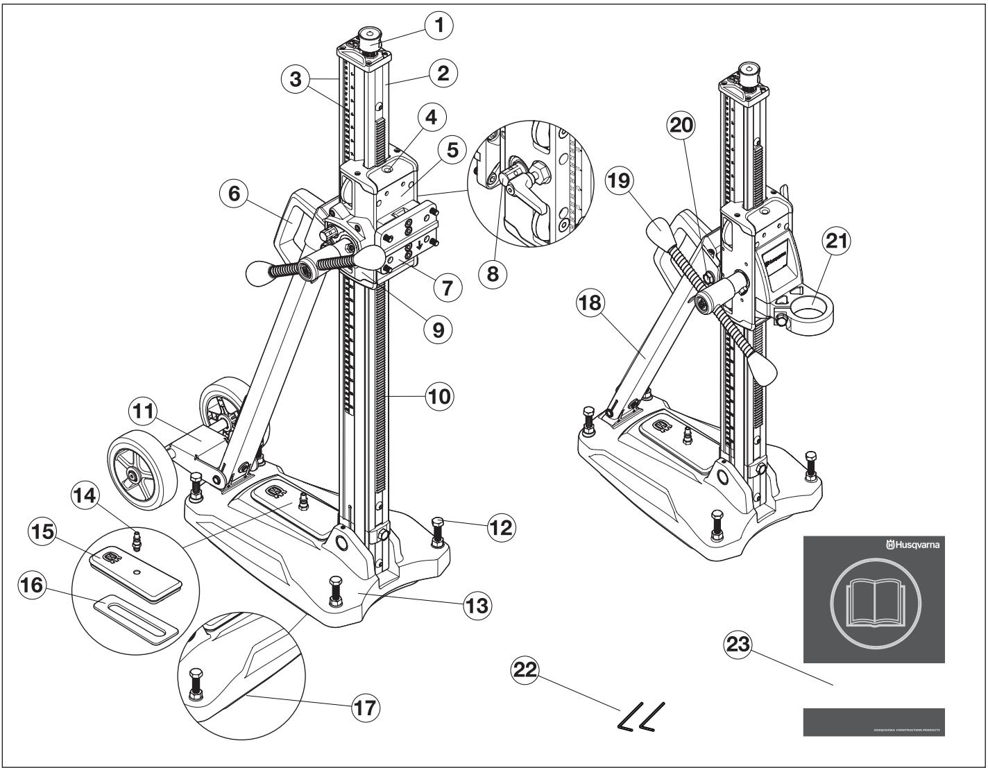
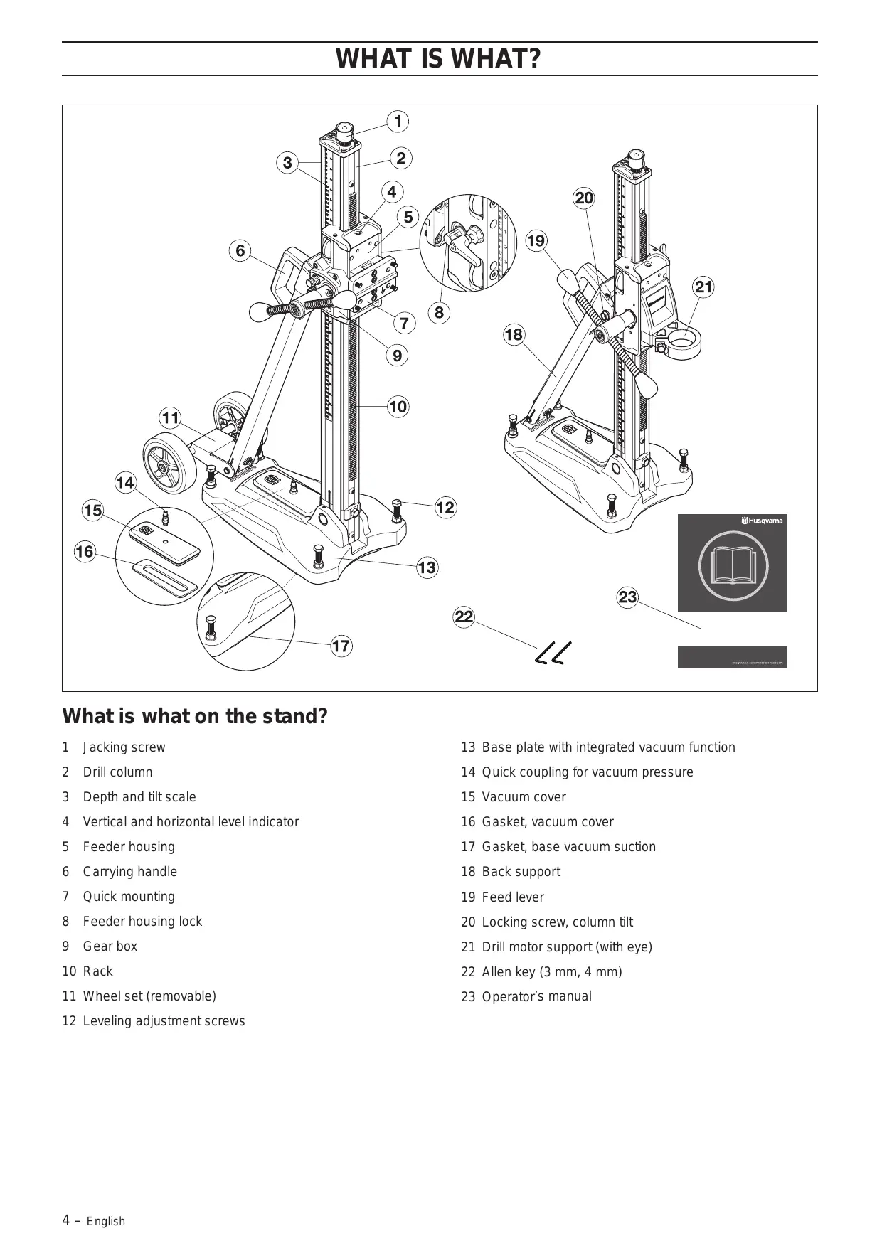
What is what on the stand?
1 Jacking screw
2 Drill column
3 Depth and tilt scale
4 Vertical and horizontal level indicator
5 Feeder housing
6 Carrying handle
7 Quick mounting
8 Feeder housing lock
9 Gear box
10 Rack
11 Wheel set (removable)
12 Leveling adjustment screws
13 Base plate with integrated vacuum function
14 Quick coupling for vacuum pressure
15 Vacuum cover
16 Gasket, vacuum cover
17 Gasket, base vacuum suction
18 Back support
19 Feed lever
20 Locking screw, column tilt
21 Drill motor support (with eye)
22 Allen key (3 mm, 4 mm)
23 Operator's manual
Steps before using a new stand
- Please read the operator's manual carefully and make sure you understand the instructions before using the machine.
- This machine is designed for and intended for drilling concrete, brick and different stone materials. All other use is improper.
- The machine is intended for use in industrial applications by experienced operators.
- Keep the workplace tidy. Disorder leads to accident risks.
- Also read the operating manual enclosed with the drill motor and check that its performance is compatible with the stand.
Always use common sense
It is not possible to cover every conceivable situation you can face. Always exercise care and use your common sense. Avoid all situations which you consider to be beyond your capability. If you still feel uncertain about operating procedures after reading these instructions, you should consult an expert before continuing.
Do not hesitate to contact your dealer if you have any more questions about the use of the machine. We will willingly be of service and provide you with advice as well as help you to use your machine both efficiently and safely.
Let your Husqvarna dealer regularly check the machine and make essential adjustments and repairs.
All information and all data in the Operator's Manual were applicable at the time the Operator's Manual was sent to print.

WARNING! Under no circumstances should you modify the original design of the machine without approval from the manufacturer. Always use original spare parts. Unauthorised modifications and/or accessories may lead to serious injury or death to the user or others.
Personal protective equipment

WARNING! You must use approved personal protective equipment whenever you use the machine. Personal protective equipment cannot eliminate the risk of injury but it will reduce the degree of injury if an accident does happen. Ask your dealer for help in choosing the right equipment.
- Protective helmet
- Hearing protection
• Protective goggles or a visor
- Breathing mask
• Heavy-duty, firm grip gloves.
- Tight-fitting, heavy-duty and comfortable clothing that permits full freedom of movement.
natural_image
Line drawing of a pair of trousers with a belt buckle (no text or symbols)• Boots with steel toe-caps and non-slip sole.

• Always have a first aid kit nearby.

General safety precautions

WARNING! Read all safety warnings and all instructions. Failure to follow the warnings and instructions may result in electric shock, fire and/or serious injury.
Work area safety
- Keep work area clean and well lit. Cluttered or dark areas invite accidents.
- People and animals can distract you causing you to lose control of the machine. For this reason, always remain concentrated and focused on the task.
- Do not use the machine in bad weather, such as dense fog, heavy rain, strong wind, intense cold, etc. Working in bad weather is tiring and can lead to dangerous conditions, e.g. slippery surfaces.
- Never start to work with the machine before the working area is clear and you have a firm foothold. Look out for any obstacles with unexpected movement. Ensure that no material can become loose and fall, causing injury when operating the machine.
- Always check the rear side of the surface where the drill bit will emerge when drilling right through. Secure and cordon off the area and make sure that no one can be injured or material damaged.
Personal safety

WARNING! There is always a risk of crush injuries when working with products containing moving parts. Wear protective gloves to avoid body injuries.
- Wear personal protective equipment. See instructions under the heading Personal protective equipment.
- Never use the machine if you are tired, if you have drunk alcohol, or if you are taking medication that could affect your vision, your judgement or your co-ordination.
- Never allow anyone else to use the machine without first ensuring that they have understood the contents of the operator's manual.
- Be careful as clothing, long hair, and jewellery can get caught in moving parts.
- Never work alone, always ensure there is another person close at hand. Apart from being able to receive help to assemble the machine, you can also get help if an accident should occur.
Use and care
- Never use a machine that is faulty. Carry out the checks, maintenance and service instructions described in this manual. Some maintenance and service measures must be carried out by trained and qualified specialists. See instructions under the heading Maintenance.
- Never use a machine that has been modified in any way from its original specification.
- Keep all parts in good working order and ensure that all fixtures are properly tightened.
Transport and storage
- Store the equipment in a lockable area so that it is out of reach of children and unauthorised persons.
- Store the drilling machine and stand in dry and frost free conditions.
Stand DS 150 and DS 250
It is our wish that you will be satisfied with your product and that it will be your companion for a long time. Think of this operator's manual as a valuable document. By following its content (using, service, maintenance etc) the life span and the second-hand value of the machine can be extended. If you will sell this machine, make sure that the buyer will get the operator's manual.
A purchase of one of our products gives you access to professional help with repairs and services. If the retailer who sells your machine is not one of our authorised dealers, ask him for the address of your nearest service workshop.
Husqvarna Construction Products has a policy of continuous product development. Husqvarna reserves the right to modify the design and appearance of products without prior notice and without further obligation introduce design modifications.
DS 150
natural_image
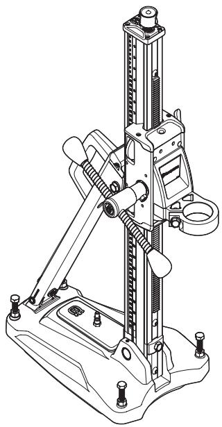
Technical line drawing of a mechanical testing rig with attached clamps and bolts (no text or symbols)- The stand is for drilling in roofs, walls and floors.
- The base plate is made of aluminium and is therefore very light weight. It has a integrated vacuum plate.
• The column can be tilted 0-60°. - The stand is fitted with a drill motor support.
- Feed lever can be used to loosen/tighten drill motor clamping, to adjust base plate leveling screws and set desired column tilt.
Accessories
- Gear box
- Wheel set (removable)
• VP 200 Vacuum pump
DS 250

natural_image
Technical line drawing of a mechanical testing apparatus with wheels and a vertical column (no text or symbols)• The stand is for drilling in roofs, walls and floors.
- The base plate is made of aluminium and is therefore very light weight. It has a integrated vacuum plate.
• The column can be tilted 0-60°.
- The drill stand is equipped with a quick connection plate for the drillmotor.
• The wheel kit is dismountable.
- The feeder housing's transmission is adjustable. The higher gives 2.25:1 and the lower, 1:1.
- Feed lever can be used to adjust base plate leveling screws and set desired column tilt.
Accessories
• VP 200 Vacuum pump
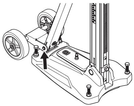
Fit the wheel kit
- Fit the wheel set in the mount on the backside of the bottom plate and tighten the screws.
natural_image
Technical line drawing of a mechanical device with wheels and mounting feet (no text or symbols)Secure the stand
There are three methods for fixing the stand.
• Securing with vacuum plate
• Fixing with expander or anchor
• Fixing with threaded rod, washer and lock nut
Securing with vacuum plate

WARNING! The vacuum plate must never be used for ceiling or wall drilling. Careless or incorrect use can result in serious, even fatal injury.
If the vacuum plate is used, make sure the support surface is not porous and can loosen from the floor or the wall. Make sure that the vacuum pump has sufficient power to secure the vacuum plate.
- Connect the vacuum pump to the quick coupling for vacuum pressure on the base plate.

natural_image
Technical line drawing of a mechanical device with wheels and a base mount (no text or symbols)- Place the bottom plate in the desired position.
- Switch on the vacuum pump. A minimum pressure of 635 mm Hg (25 inch Hg) must be reached so that the base plate seals tightly against the surface.
Fixing with expander or anchor
IMPORTANT! When drilling roofs, only expander or anchor suitable for surfaces exposed to tensile forces should be used.
Use only expander or anchor which is approved for current application.
DS 150

- Drill a hole for the expander/anchor at a distance of 293 mm (11.5") from the center of the hole.
- Bolt down the base plate. Check carefully that the expander is secured correctly.
- The bottom plate can be adjusted to the surface by using the leveling adjustment screws. Use the feed lever.
DS 250
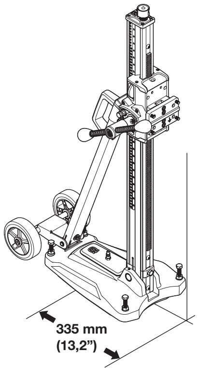
- Drill a hole for the expander/anchor at a distance of 335 mm (13.2") from the centre of the hole.
- Bolt down the base plate. Check carefully that the expander is secured correctly.
- The bottom plate can be adjusted to the surface by using the leveling adjustment screws. Use the feed lever.
Fixing with threaded rod, washer and lock nut
If the mounting surface is inadequate for drilling in roofs or walls, the base plate can be fixed using a threaded rod, which is mounted on the backside with a washer and lock nut.
Assembly of drill motor
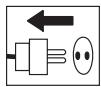
IMPORTANT! Always pull out the plug from the outlet socket before cleaning, maintenance or assembly.
- Always remove the drill bit before the motor is mounted or dismounted.
- Lock the feed housing lock.
DS 150
- Fasten the drill spindle on the drill motor support. Use the feed lever.

natural_image
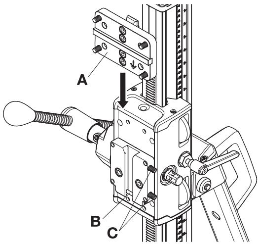
Technical line drawing of a mechanical device with hoses and a valve (no text or symbols)DS 250
• Fit the drill motor on the quick mount (A).
- Mount the quick mounting and drilling machine in the track on the locking clamp. Make sure that the quick-mount is pushed all the way to the bottom (B) of the rail on the locking clip.
- Secure with the locking screws (C).
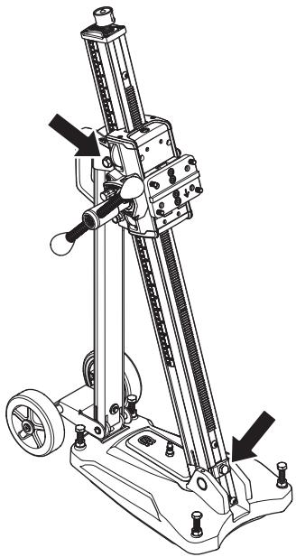
Adjust the column tilt
natural_image
Technical line drawing of a mechanical device with wheels and adjustment knobs (no text or symbols)Loosen the locking screws for column tilt and set the desired drill angle. Tighten the locking screws. Use the feed lever. The column can be tilted 0-60°.
The angle indicator can be used for approximate adjustment. If higher precision is required, alternative measuring methods should be used.
Drilling in the ceiling

WARNING! Use a water collector to avoid water penetrating into the machine. The machine must be covered with plastic or the like in order to prevent water penetrating into the machine, but do not cover the air intakes and air outlets.
MAINTENANCE
Stand maintenance

WARNING! Inspection and/or maintenance should be carried out with the motor switched off and the plug disconnected.
The lifetime of your machine can be extended considerably if it is used, cared for and maintained in the proper manner.
Cleaning and lubrication
IMPORTANT! Remove the drill motor.
- It is important that the drill stand is kept clean for functionality to be maintained.
- Clean the stand using a high pressure washer and then wipe dry.
- Lubricate the moving parts on the stand. Apply grease to counteract corrosion on the contact surfaces.
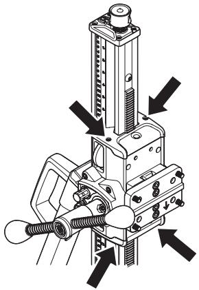
Adjusting the feed housing
If there is play between the column and the feed housing, the play must be adjusted.
- Remove top and bottom plastic carriage covers.
natural_image
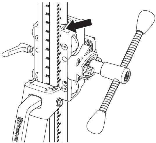
Technical line drawing of a mechanical assembly with no visible text or symbols- Loosen set screws holding guide roller shafts.
natural_image
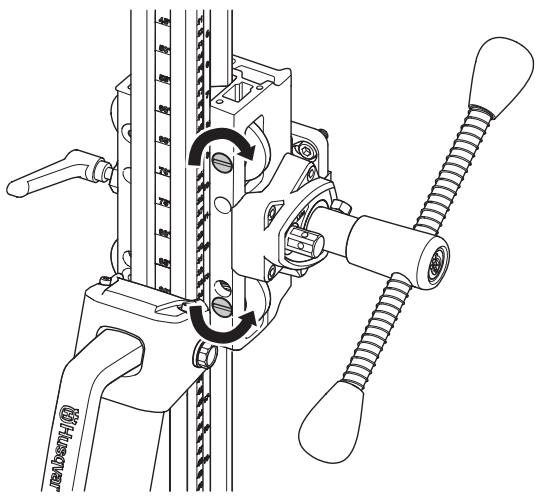
Technical line drawing of a mechanical clamp or bracket assembly with no visible text or symbols- Start with the top guide roller. Use a flat screwdriver and turn clockwise to guide the roller closer to the column.
- Tighten set screw to lock the guide roller shaft.
- Adjust the lower roller by screwing anti-clockwise to guide the roller nearer to the column.
natural_image
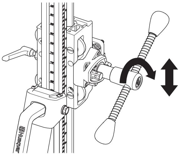
Technical line drawing of a mechanical clamp or clamping device with no visible text or symbols- Tighten set screw to lock the guide roller shaft.
- Use the feed lever to see if the feed housing moves smoothly on the column. If not, adjust the rollers again.
natural_image
Technical diagram of a mechanical clamp or spring device with no visible text or symbols• Fit the top and bottom plastic carriage covers.
Repairs
IMPORTANT! All types of repairs may only be carried out by authorised repairmen. This is so that the operators are not exposed to great risks.
Daily maintenance
1 Check that nuts and screws are tight.
2 Clean the outside of the machine.
3 Check that the feed crank can be moved without resistance.
4 Check that the gearing moves easily and does not cause any noise.
5 Check for any wear or damage on the column.
6 Check that the feed housing can be moved easily and does not backlash against the stand column.
TECHNICAL DATA
| DS 150 | DS 250 | |
| Dimensions | ||
| Height, mm/inches | 862/33,9 | 1052/41,4 |
| Width, mm/inches | 266/10,5 | 266/10,5 |
| Depth, mm/inches | 522/20,6 | 545/21,5 |
| Weight, kg/lbs | 14/30,9 | 14,5/32 |
| Travel length, mm/inch | 495/19,5 | 686/27 |
| Max. drill diameter, mm/inches | 150/6 | 250/10 |
| The column's angling | 0-60° | 0-60° |
EC-declaration of conformity
(Applies to Europe only)
Husqvarna Construction Products, SE-433 81 Göteborg, Sweden, tel: +46-31-949000, declares under sole responsibility that the stands Husqvarna DS 150 and DS 250 from 2008's serial numbers and onwards (the year is clearly stated in plain text on the type plate with subsequent serial number) are in conformity with the requirements of the COUNCIL'S DIRECTIVES:
- of June 22, 1998 "relating to machinery" 98/37/EC, annex IIA.
The following standards have been applied:
SE-EN12348
The supplied stand conforms to the example that underwent EC type examination. The stand must conform to applicable regulations, EU-requirements as well as national requirements.
Göteborg 3 April 2008

Ulf Petersson, Development manager
natural_image
Line drawing of a pair of trousers with a belt buckle (no text or symbols)natural_image
Technical line drawing of a mechanical device with no visible text or symbolsnatural_image
Technical line drawing of a mechanical testing apparatus with wheels and a vertical rail (no text or symbols)natural_image
Technical line drawing of a mechanical device with wheels and mounting points (no text or symbols)Sujeción de la base
natural_image
Technical line drawing of a mechanical device with wheels and a base mount (no text or symbols)natural_image
Technical line drawing of a mechanical device with hoses and a dial (no text or symbols)DS 250
natural_image
Technical line drawing of a mechanical device with wheels and adjustment knobs (no text or symbols)natural_image
Technical line drawing of a mechanical assembly with no visible text or symbolsnatural_image
Technical line drawing of a mechanical clamp or bracket assembly with no visible text or symbolsnatural_image
Technical line drawing of a mechanical clamp or clamping device with no visible text or symbolsnatural_image
Technical line drawing of a mechanical clamp or spring assembly with directional arrows indicating movement (no text or symbols)natural_image
Line drawing of a pair of trousers with a belt buckle (no text or symbols)natural_image
Technical line drawing of a mechanical testing apparatus with no visible text or symbolsnatural_image
Technical line drawing of a mechanical testing apparatus with wheels and a vertical column (no text or symbols)natural_image
Technical line drawing of a mechanical device with wheels and mounting feet (no text or symbols)natural_image
Technical line drawing of a mechanical device with wheels and mounting points (no text or symbols)natural_image
Mechanical assembly diagram showing a vertical rail with attached components and a directional arrow (no text or symbols)DS 250
natural_image
Technical line drawing of a mechanical device with gears and shafts (no text or symbols)natural_image
Technical line drawing of a mechanical assembly with no visible text or symbolsnatural_image
Technical line drawing of a mechanical clamp or bracket assembly (no text or symbols)natural_image
Technical line drawing of a mechanical clamp or clamping device with no visible text or symbolsnatural_image
Technical diagram of a mechanical clamp or clamp device with no visible text or symbolsnatural_image
Line drawing of a pair of trousers with a belt buckle (no text or symbols)natural_image
Technical line drawing of a mechanical testing apparatus with no visible text or symbolsnatural_image
Technical line drawing of a mechanical testing apparatus with wheels and a vertical column (no text or symbols)natural_image
Technical line drawing of a mechanical device with wheels and mounting points (no text or symbols)Sécuriser le bâti
natural_image
Technical line drawing of a mechanical device with wheels and mounting points (no text or symbols)natural_image
Technical line drawing of a mechanical device with hoses and a dial (no text or symbols)DS 250
natural_image
Technical line drawing of a mechanical device with gears and shafts (no text or symbols)natural_image
Mechanical assembly diagram showing a vertical actuator with threaded components and directional arrows indicating motion (no text or labels)natural_image
Technical line drawing of a mechanical clamp or bracket assembly (no text or symbols)natural_image
Technical line drawing of a mechanical clamp or clamping device with no visible text or symbolsnatural_image
Technical diagram of a mechanical clamp or bracket assembly with no visible text or symbols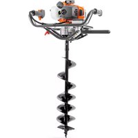
- Symbols on the machine:
- Symbols in the operator's manual:
- CONTENTS
- KEY TO SYMBOLS
- WHAT IS WHAT?
- SAFETY INSTRUCTIONS
- PRESENTATION
- ASSEMBLY
- MAINTENANCE
- TECHNICAL DATA
- What is what on the stand?
- Steps before using a new stand
- Always use common sense
- Personal protective equipment
- General safety precautions
- Work area safety
- Personal safety
- Use and care
- Transport and storage
- Stand DS 150 and DS 250
- Accessories
- Fit the wheel kit
- Secure the stand
- Securing with vacuum plate
- Fixing with expander or anchor
- Fixing with threaded rod, washer and lock nut
- Assembly of drill motor
- DS 150
- DS 250
- Adjust the column tilt
- Drilling in the ceiling
- Stand maintenance
- Cleaning and lubrication
- Adjusting the feed housing
- Repairs
- Daily maintenance
- EC-declaration of conformity
- (Applies to Europe only)
- Sujeción de la base
- Sécuriser le bâti
Brand : HUSQVARNA
Model : DS 150
Category : Drill