
KU059 - Saw KRESS - Free user manual and instructions
Find the device manual for free KU059 KRESS in PDF.
| Product Type | Portable Workbench / Vise |
| Brand | Kress |
| Model | KU059 |
| Clamping Range | 0–940 mm |
| Maximum Clamping Force | 1 ton (1000 kg) |
| Maximum Load | 272 kg |
| Pedal Travel | 24 mm per step |
| Weight | 19 kg |
| Dimensions (unfolded) | 1000 x 985 x 885 mm |
| Dimensions (folded) | 775 x 350 x 335 mm |
| Material | Solid Steel |
| Clamping Method | Foot Operation (pedal) |
| Number of Jaws | 2 (one fixed, one movable) |
| Included Accessories | Jaw Covers (2 pieces) |
| Maintenance and Cleaning | Clean with a dry cloth; no water or chemical cleaners |
| Safety | Safety glasses, gloves, dust mask recommended; do not stand on the device |
| Spare Parts and Repairability | No user-serviceable parts; repair by a professional |
| General Information | Directive 2006/42/EC; max pedal pressure: 100 kg |
| Safety Symbols | Read manual, eye/ear protection, pinching risk, wear gloves |
Frequently Asked Questions - KU059 KRESS
User questions about KU059 KRESS
0 question about this device. Answer the ones you know or ask your own.
Ask a new question about this device
Download the instructions for your Saw in PDF format for free! Find your manual KU059 - KRESS and take your electronic device back in hand. On this page are published all the documents necessary for the use of your device. KU059 by KRESS.
USER MANUAL KU059 KRESS
natural_image
Line drawing of a bipod assembly with Kresser branding (no text or symbols on the device itself)| Hands-free clamping and holding portable workstation | EN | P07 | |
| Mobile Werkbank mit freihändiger Einspannfunktion | DE | P10 | |
| Poste de travail portable de serrage et de tenue mains-libres | FR | P13 | |
| Stazione di lavoro portatile per fissaggio e bloccaggio a mani libere | IT | P16 | |
| Mesa portátil de trabajo manos libres | ES | P19 | |
| Estação de trabalho portátil, de fixação e suporte mãos- livres | PT | P22 | |
| Werkstation dat vastklemt en vasthoudt waarbij uw handen vrij zijn | NL | P25 | |
| Портативный верстак позволяющий зажимать и удерживать RU | RU | P28 | 6 |
| Zaciskanie i unieruchamianie bez użycia rąk przenośny stół roboczy | PL | P32 |
natural_image
Technical line drawing of a mechanical device with an arrow indicating direction (no text or symbols present)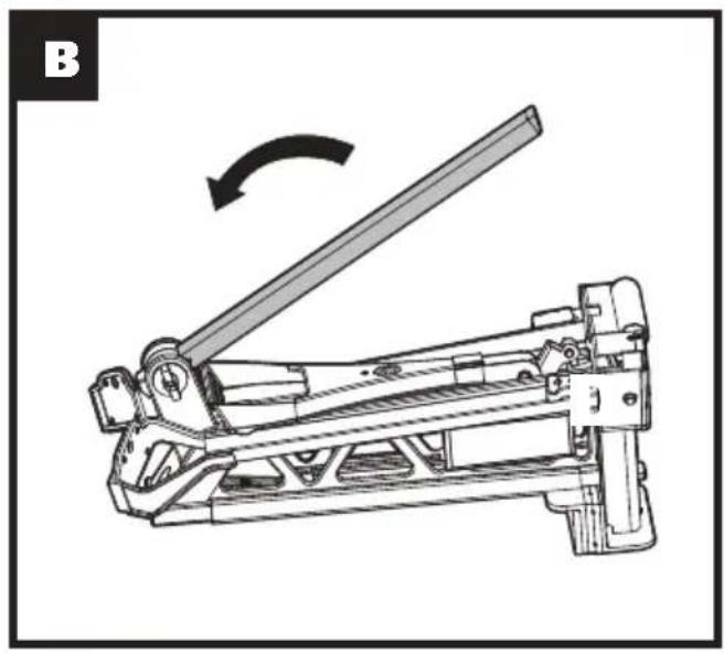
natural_image
Technical line drawing of a mechanical lever mechanism with an arrow indicating rotational motion (no text or symbols present)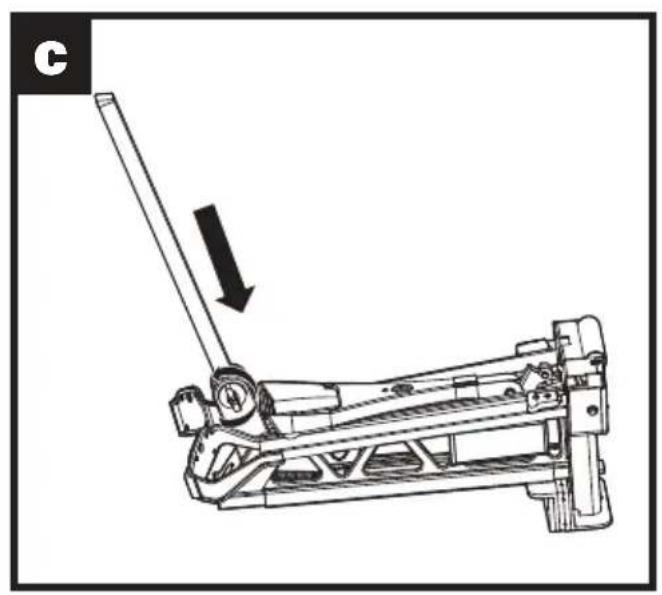
natural_image
Mechanical lever mechanism diagram showing a lever and pivot point (no text or symbols)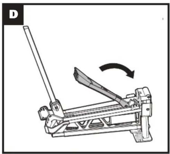
natural_image
Mechanical lever mechanism diagram showing a lever and blade assembly (no text or symbols)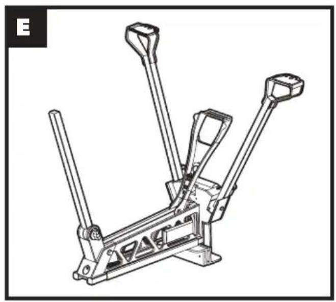
natural_image
Technical line drawing of a mechanical lever assembly (no text or symbols)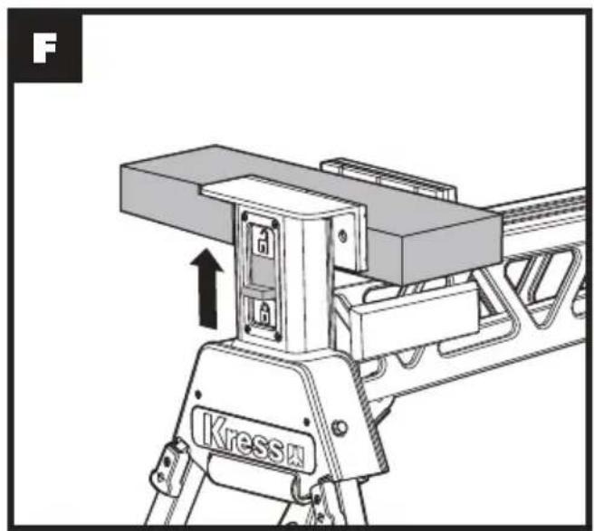
natural_image
Technical diagram of a Kress motor assembly with no visible text or symbols
natural_image
Mechanical lever mechanism diagram showing a rotating lever and adjustment, with an inset close-up of the lever handle (no text or symbols)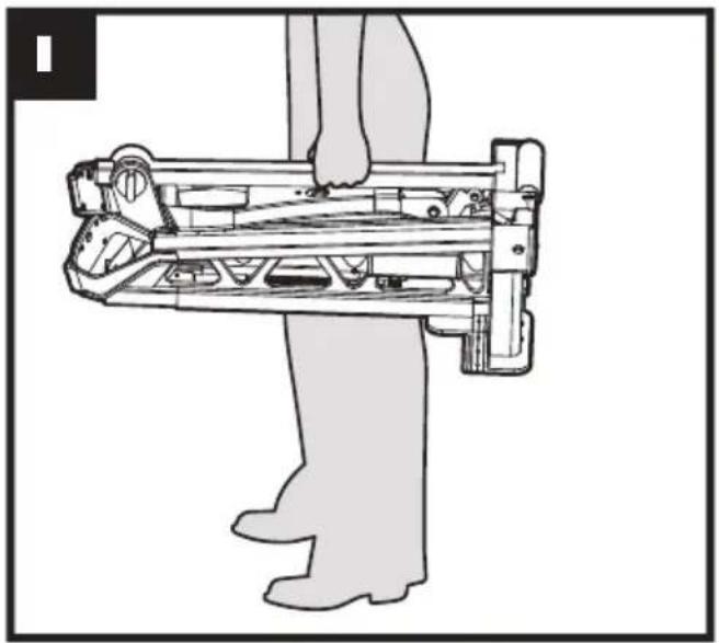
natural_image
Line drawing of a person using a mechanical device (no text or symbols present)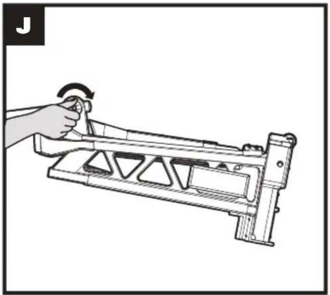
natural_image
Illustration of a hand holding a mechanical lever with a curved arrow indicating rotation (no text or symbols)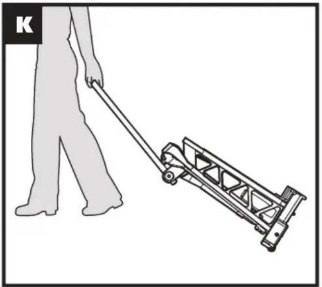
natural_image
Illustration of a person pushing a manual push cart (no text or symbols)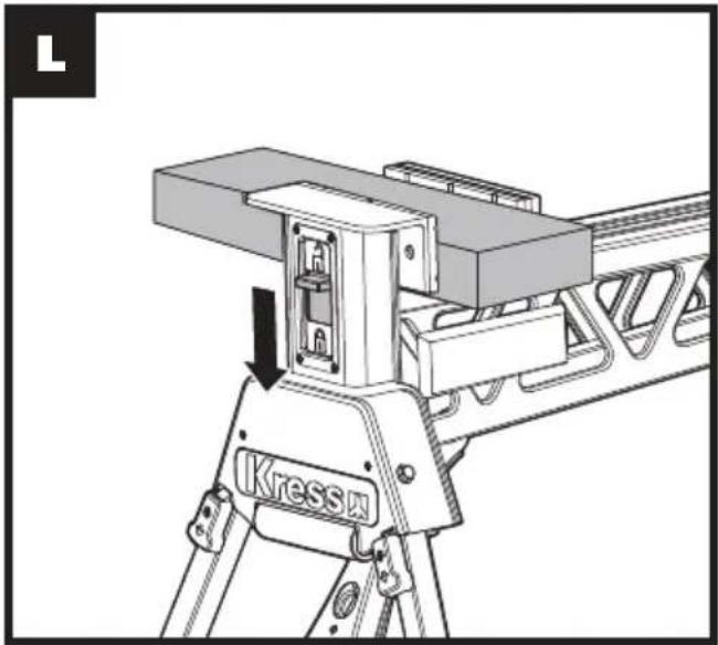
natural_image
Technical line drawing of a mechanical device with a labeled component 'Kress' and directional arrow (no readable text or symbols beyond label)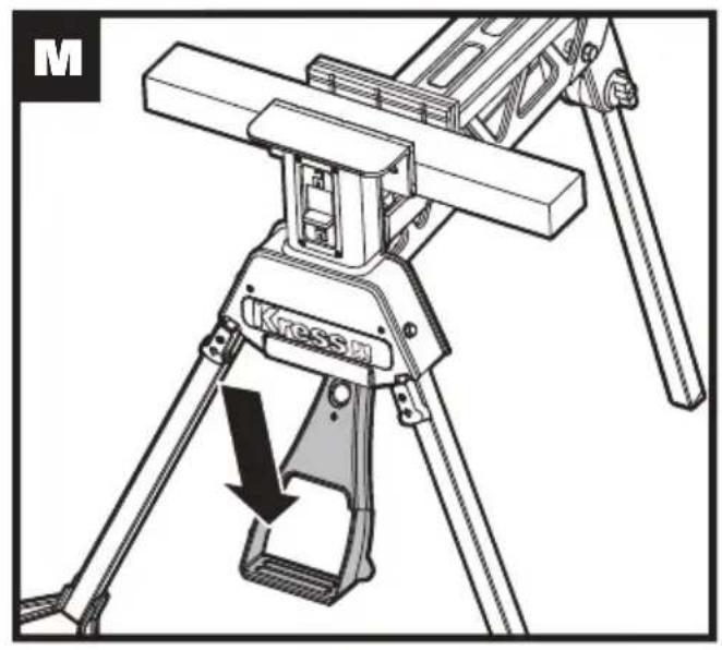
natural_image
Technical line drawing of a Kressi apparatus with tripod base and lever mechanism (no text or symbols)
natural_image
Technical illustration of a mechanical assembly with an arrow indicating direction (no text or symbols present)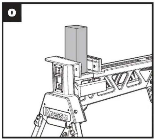
natural_image
Technical line drawing of a mechanical assembly with no visible text or symbols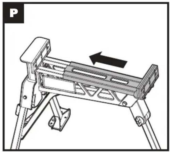
natural_image
Technical line drawing of a mechanical device with an arrow indicating motion direction (no text or symbols)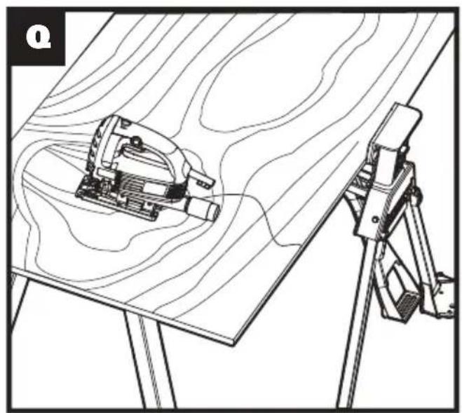
natural_image
Technical line drawing of a mechanical assembly with a tool and tripod, no visible text or symbols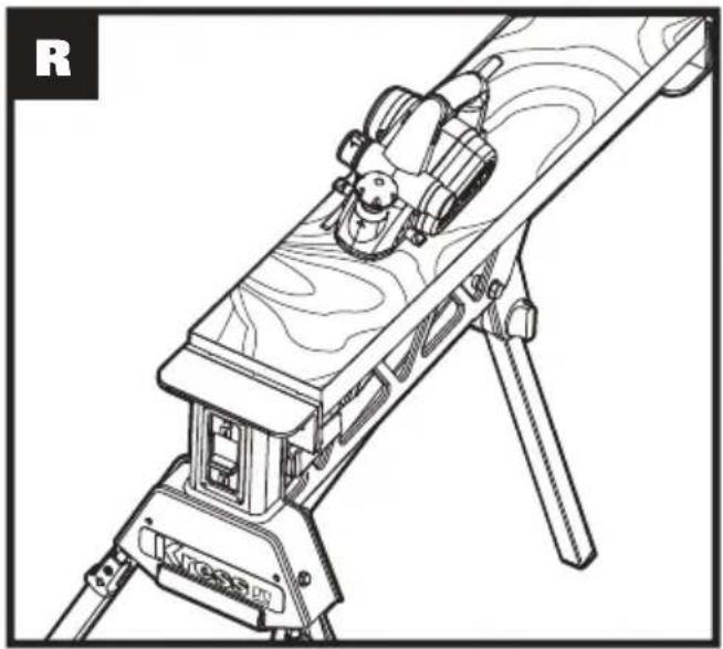
natural_image
Line drawing of a mounted optical or target device with wooden base and tripod, no visible text or symbols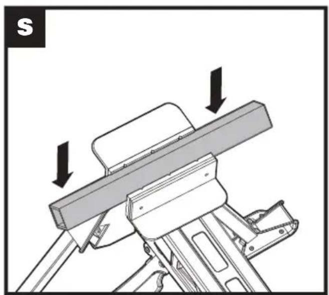
natural_image
Mechanical assembly diagram showing a lever mechanism with arrows indicating motion direction (no text or symbols)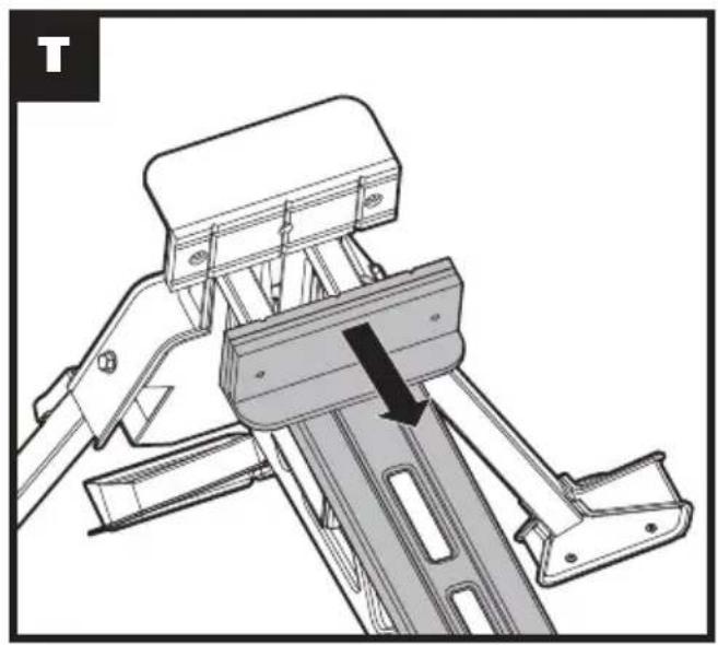
natural_image
Technical line drawing of a mechanical device with lever and bracket assembly (no text or symbols)SAFETY INSTRUCTIONS
WARNING! When using this product basic safety precautions should always be followed. Failure to follow all instructions listed below may result in personal injury.
Read all these instructions before attempting to operate this product and save these instructions.
- Keep work area clear and well lit. Cluttered areas and benches invite injuries.
- Make sure all moving parts are free from interference.
- Ensure workstation is set up on firm, level ground in a stable manner.
- Keep other persons away. Do not let persons, especially children, not involved in the work touch the tool and keep them away from the work area.
- Be aware of over-balancing. When a large piece is cut from one end of a job, the remaining piece may be heavy enough to tip the workstation. Always ensure the workpiece is well supported.
- Check to make sure that all fixing screws and knobs are tight and all legs are locked into place before operating the workstation.
- The tool must be used only for its prescribed purpose. Any use other than those mentioned in these instructions will be considered a case of misuse. The manufacturer shall not be liable for any damage or injury resulting from such cases of misuse.
- Never stand on this product.
- Dress properly. Do not wear loose clothing or jewelry, they can be caught in moving parts. Non-skid footwear is recommended when working outdoors. Wear protective hair covering to contain long hair.
- Use personal protective equipment. Use safety glasses. Use face or dust mask if working operations create dust.
- Save all warnings and instructions for future reference. Refer to them frequently and use them to instruct others who may use workstation. If you loan someone workstation, loan them these instructions also to prevent misuse of the product and possible injury.
- Do not use tools in damp or wet locations. Moist work piece and environment can not clamp firmly.
- Ensure the work piece was clamped firmly and the lock release switch is on proper state before use.
- Check damaged parts. Before further use of tool, it should be carefully checked to determine that it will operate properly and perform its intended function.
- When not in use, tools should be stored in a dry locked-up place, out of the reach of children and do not allow persons unfamiliar with it.
-
Have your workstation serviced by a qualified repair person.
-
Warning! The use of any accessory or attachment other than one recommended in this instruction manual may present a risk of personal injury.
SYMBOLS
 | Read the operator's manual. |
 | Warning |
 | Wear eye protection |
 | Wear ear protection |
 | Pinch points |
 | Wear gloves |
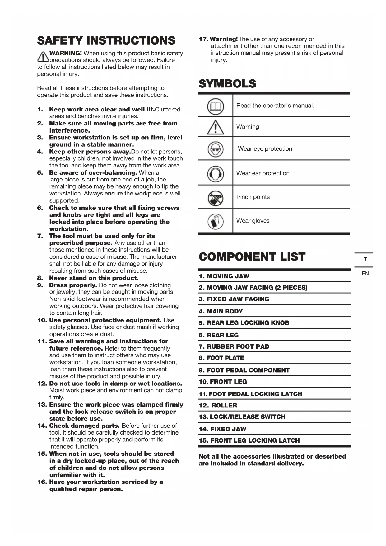
COMPONENT LIST
| 1. MOVING JAW |
| 2. MOVING JAW FACING (2 PIECES) |
| 3. FIXED JAW FACING |
| 4. MAIN BODY |
| 5. REAR LEG LOCKING KNOB |
| 6. REAR LEG |
| 7. RUBBER FOOT PAD |
| 8. FOOT PLATE |
| 9. FOOT PEDAL COMPONENT |
| 10. FRONT LEG |
| 11. FOOT PEDAL LOCKING LATCH |
| 12. ROLLER |
| 13. LOCK/RELEASE SWITCH |
| 14. FIXED JAW |
| 15. FRONT LEG LOCKING LATCH |
Not all the accessories illustrated or described are included in standard delivery.
TECHNICAL DATA
| Clamping range 0-940mm | |
| Max. clamping force 1 metric ton | (1000kg) |
| Clamp method Foot step | |
| Max. Load 272kg | |
| Footprint (standing) 1000x985x885mm | |
| Footprint (folded) 775x350x335mm | |
| Clamp travel – foot pedal 24mm per step | |
| Weight 19kg | |
| Construction Solid steel | |
OPERATING INSTRUCTIONS

NOTE: Before using the tool, read the instruction book carefully.
INTENDED USE
The workbench is a versatile workstation for holding, clamping, supporting.
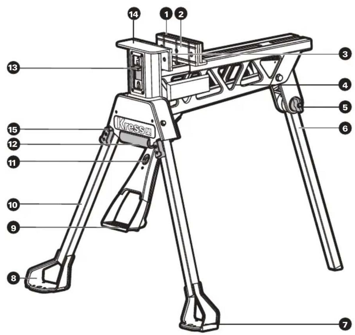
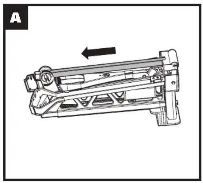
1. SET-UP INSTRUCTIONS
- Put the workbench upside down on the ground, loosen the Rear Leg Locking Knob (5) and slide the rear leg from its storage position. Pivot the leg to position and slide it all the way upward then lift and slide it fully into its housing at the rear. Tighten the knob. (See Fig. A-C)
- Raise the Foot Pedal (9) until it "clicks" into position. (See Fig. D-E)
- Rotate the Front Legs (10) all the way forward until they "click" into position. The Front Leg Locking Latch (15) will be open automatically. (See Fig. E)
- Turn the workbench upright and recheck that all legs are locked firmly in position.
2. FOLDING INSTRUCTIONS
Folding is the reverse procedure of above. (See Fig. F-K)
- Ensure that the Lock / Release Switch (13) is in the "unlock position". (See Fig. F)
- Turn the unit upside down. Slide the front leg latch and fold the Front Legs (10) into position. (See Fig. G)
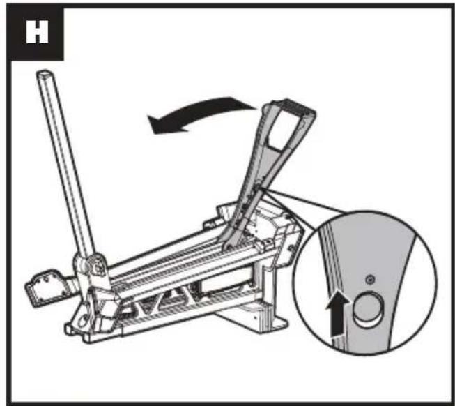
- Draw the Foot Pedal (9) locking latch and place the Foot Pedal in folding position. (See Fig. H)
- Loosen the Rear Locking Knob(5). Slide the Rear Leg (6) from housing and back into storage position. Make sure the Rear Leg is engaged fully into storage position and the Rear Leg Locking Knob is tightened firmly.
- You can carry the Rear Leg as a carry handle when the workbench is fully folded in its position. (See Fig. I)
- You can also slide the Rear Leg to use as a handle. With the Roller (12) on the front, transporting the workbench is easy and fast. Note that the Roller is not designed to withstand rigorous transport, such as bouncing down stairways or traversing rough terrain. (See Fig. J, K)
3. CLAMPING
- Place the workpiece against the Fixed Jaw (14) and slide the Moving Jaw (1) forward until it touches the workpiece.
The Foot Pedal (9) can be pressed repeatedly to make the jaw move forward. - Slide the Lock / Release Switch (13) down to the "lock" position. (See Fig. L)
- Apply downward pressure on the Foot Pedal until enough clamping force is applied. (See Fig. M)
WARNING: Maximum allowable force on the foot pedal is 100kg. Do not stand or jump on the unit, as you can cause injury or damage to the unit.
4. RELEASING
- Slide the Lock / Release Switch (13) up to the "release" position. (See Fig. F)
- Push on the Foot Pedal(9), allow it to return up and release the workpiece. (See Fig. M)
If you have clamped the object very tightly, you must exert similar pressure on the foot pedal before it will release.
WARNING: Ensure you are supporting the workpiece to avoid its falling when the jaw is released.
- Slide the moving jaw back and remove your workpiece. (See Fig. N)
5. CLAMPING ON ONE SIDE OF THE JAW
Sometimes, large or awkward workpieces can only be clamped on one side of the jaws. In this case, be sure to avoid excessive clamping force.
6. CLAMPING SQUARE PIECES VERTICALLY (See Fig.0)
Sometimes, tubing or other square (steel, aluminum or other) workpieces need to be clamped vertically on the center of the jaws. The hole on the base plate under the jaw accommodates pieces up to 6cm in width.
7. CLAMPING LARGE OBJECTS [450mm TO 940mm]
The move jaw can be reversed to accommodate large workpieces.
- Set the Lock / Release Switch (13) to the "release" position and ensure that the Foot Pedal (9) is released.
- Slide the Moving Jaw (1) fully from its tracks. (See Fig. N)
- Rotate the jaw 180 degrees and re-insert it into the track. (See Fig. P)
WARNING: Whenever clamping objects with the moving jaw reversed, ensure the workpiece sits down onto the sliding jaw, and is parallel to it. Avoid clamping workpieces at the top of the jaws (with a gap between the workpiece and the base of the moving jaw) as excessive pedal pressure could damage the unit.
Note: Some operations such as hand sawing or planing exert enough pressure to cause the workbench to slide. In these situations, it is acceptable to hold the workbench in place by standing on the foot plate. (See Fig. R) When clamping large or heavy materials,
provide outboard support. Never step on the footplate to prevent workbench from tipping over, especially when using power tools. (See Fig.Q)
8. CLAMPING SQUARE TUBING
Clamp square tubing or similar material either on the diagonal or flat side. Use the jaws to securely hold your material. (See Fig. S)
9. REMOVING THE JAW FACINGS (See Fig.T)
The jaw facings can be removed to achieve a greater clamping range, replace if worn or damaged, or when fitting the optional jaws.
Remove the screws in the center of jaws, the jaw facing (2, 3) can be pulled off from the jaw by hand.
MAINTENANCE
Your tool requires no additional lubrication or maintenance.
There are no user serviceable parts in your tool. Never use water or chemical cleaners to clean your tool.
Wipe clean with a dry cloth. Always store your tool in a dry place.
ENVIRONMENTAL PROTECTION

Disposal
The machine, its accessories and packaging materials should be sorted for environmentally friendly recycling. The plastic components are labeled for
categorized recycling.
DECLARATION OF CONFORMITY
We,
Positec Germany GmbH
Postfach 32 02 16, 50796 Cologne, Germany
Declare that the product
Description Portable versatile workstation
Type KU059
Function Being used as worktable and bench vise
Complies with the following Directives:
2006/42/EC
The person authorized to compile the technical file,
Name Marcel Filz
Address Positec Germany GmbH
Postfach 32 02 16, 50796 Cologne, Germany

2021/11/04
Allen Ding
Deputy Chief Engineer, Testing & Certification
Positec Technology (China) Co., Ltd
18, Dongwang Road, Suzhou Industrial
Park, Jiangsu 215123, P. R. China
SICHERHEITSHINWEISE
18, Dongwang Road, Suzhou Industrial
Park, Jiangsu 215123, P. R. China
MESURES DE SECURITE

DÉCLARATION DE CONFORMITÉ
Nous,
POSITEC Germany GmbH
Postfach 32 02 16, 50796 Cologne, Germany
Positec Technology (China) Co., Ltd 18, Dongwang Road, Suzhou Industrial Park, Jiangsu 215123, P. R. China
Sometimes, tubing or other square (steel, aluminum or other) workpieces need to be clamped vertically on the center of the jaws. The hole on the base plate under the jaw accommodates pieces up to 6cm in width.
7. BLOCCAGGIO DI OGGETTI DI GRANDI DIMENSIONI [450mm \~ 940mm]
18, Dongwang Road, Suzhou Industrial
Park, Jiangsu 215123, P. R. China
18, Dongwang Road, Suzhou Industrial
Park, Jiangsu 215123, P. R. China
INSTRUÇÕES DE SEGURANÇA
18, Dongwang Road, Suzhou Industrial
Park, Jiangsu 215123, P. R. China
VEILIGHEIDS INSTRUCTIES

2. OPVOUWINSTRUCTIES
18, Dongwang Road, Suzhou Industrial
Park, Jiangsu 215123, P. R. China
18, Dongwang Road, Suzhou Industrial
Park, Jiangsu 215123, P. R. China
ZALECENIA DOTYCZĄCE BEZPIECZEŃSTWA

18, Dongwang Road, Suzhou Industrial
Park, Jiangsu 215123, P. R. China
Kress


- SAFETY INSTRUCTIONS
- COMPONENT LIST
- TECHNICAL DATA
- OPERATING INSTRUCTIONS
- INTENDED USE
- SET-UP INSTRUCTIONS
- FOLDING INSTRUCTIONS
- CLAMPING
- WARNING: Maximum allowable force on the foot pedal is 100kg. Do not stand or jump on the unit, as you can cause injury or damage to the unit.
- RELEASING
- WARNING: Ensure you are supporting the workpiece to avoid its falling when the jaw is released.
- CLAMPING ON ONE SIDE OF THE JAW
- CLAMPING SQUARE PIECES VERTICALLY (See Fig.0)
- CLAMPING LARGE OBJECTS [450mm TO 940mm]
- WARNING: Whenever clamping objects with the moving jaw reversed, ensure the workpiece sits down onto the sliding jaw, and is parallel to it. Avoid clamping workpieces at the top of the jaws (with a gap between the workpiece and the base of the moving jaw) as excessive pedal pressure could damage the unit.
- CLAMPING SQUARE TUBING
- REMOVING THE JAW FACINGS (See Fig.T)
- MAINTENANCE
- ENVIRONMENTAL PROTECTION
- Disposal
- DECLARATION OF CONFORMITY
- SICHERHEITSHINWEISE
- MESURES DE SECURITE
- DÉCLARATION DE CONFORMITÉ
- BLOCCAGGIO DI OGGETTI DI GRANDI DIMENSIONI [450mm \~ 940mm]
- INSTRUÇÕES DE SEGURANÇA
- VEILIGHEIDS INSTRUCTIES
- OPVOUWINSTRUCTIES
- ZALECENIA DOTYCZĄCE BEZPIECZEŃSTWA
- Kress
Brand : KRESS
Model : KU059
Category : Saw