B365M Phantom Gaming 4 - Motherboard ASROCK - Free user manual and instructions
Find the device manual for free B365M Phantom Gaming 4 ASROCK in PDF.

User questions about B365M Phantom Gaming 4 ASROCK
0 question about this device. Answer the ones you know or ask your own.
Ask a new question about this device
Download the instructions for your Motherboard in PDF format for free! Find your manual B365M Phantom Gaming 4 - ASROCK and take your electronic device back in hand. On this page are published all the documents necessary for the use of your device. B365M Phantom Gaming 4 by ASROCK.
USER MANUAL B365M Phantom Gaming 4 ASROCK
Published December 2018
Copyright©2018 ASRock INC. All rights reserved.
Copyright Notice:
No part of this documentation may be reproduced, transcribed, transmitted, or translated in any language, in any form or by any means, except duplication of documentation by the purchaser for backup purpose, without written consent of ASRock Inc.
Products and corporate names appearing in this documentation may or may not be registered trademarks or copyrights of their respective companies, and are used only for identification or explanation and to the owners' benefit, without intent to infringe.
Disclaimer:
Specifications and information contained in this documentation are furnished for informational use only and subject to change without notice, and should not be constructed as a commitment by ASRock. ASRock assumes no responsibility for any errors or omissions that may appear in this documentation.
With respect to the contents of this documentation, ASRock does not provide warranty of any kind, either expressed or implied, including but not limited to the implied warranties or conditions of merchantability or fitness for a particular purpose.
In no event shall ASRock, its directors, officers, employees, or agents be liable for any indirect, special, incidental, or consequential damages (including damages for loss of profits, loss of business, loss of data, interruption of business and the like), even if ASRock has been advised of the possibility of such damages arising from any defect or error in the documentation or product.

This device complies with Part 15 of the FCC Rules. Operation is subject to the following two conditions:
(1) this device may not cause harmful interference, and
(2) this device must accept any interference received, including interference that may cause undesired operation.
CALIFORNIA, USA ONLY
The Lithium battery adopted on this motherboard contains Perchlorate, a toxic substance controlled in Perchlorate Best Management Practices (BMP) regulations passed by the California Legislature. When you discard the Lithium battery in California, USA, please follow the related regulations in advance.
"Perchlorate Material-special handling may apply, see www.dtsc.ca.gov/hazardouswaste/perchlorate"
ASRock Website: http://www.asrock.com

AUSTRALIA ONLY
Our goods come with guarantees that cannot be excluded under the Australian Consumer Law. You are entitled to a replacement or refund for a major failure and compensation for any other reasonably foreseeable loss or damage caused by our goods. You are also entitled to have the goods repaired or replaced if the goods fail to be of acceptable quality and the failure does not amount to a major failure. If you require assistance please call ASRock Tel : +886-2-28965588 ext.123 (Standard International call charges apply)
The terms HDMI ^® and HDMI High-Definition Multimedia Interface, and the HDMI logo are trademarks or registered trademarks of HDMI Licensing LLC in the United States and other countries.

HIGH-DEFINITION MULTIMEDIA INTERFACE
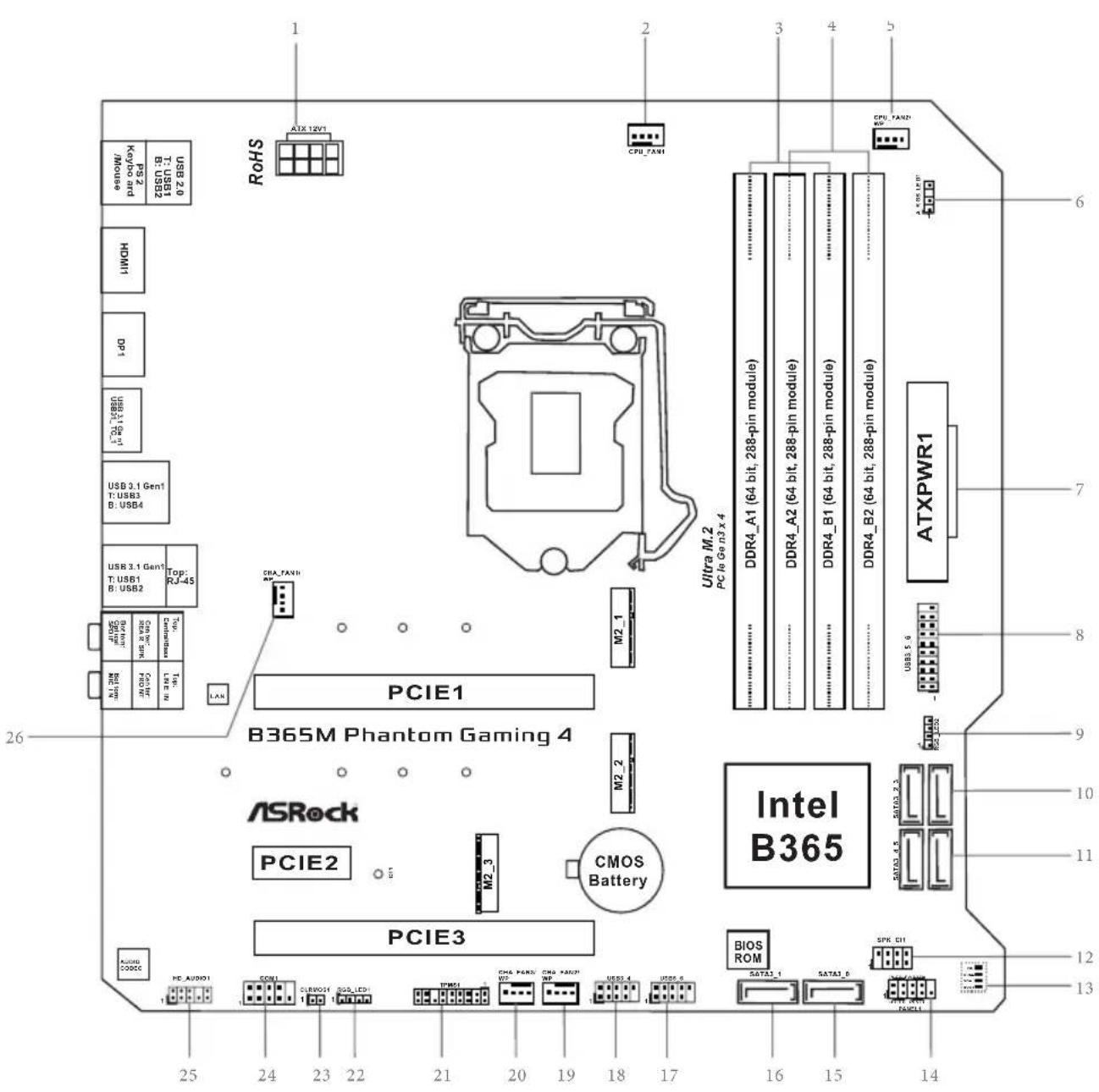
Motherboard Layout
text_image
RoHS CPU_FAN1 ATX 12V1 CPU_FAN2 USB 2.0 USB 2.0 HDMI DPU USB 3.1 Gen1 T: USB3 B: USB4 USB 3.1 Gen1 T: USB1 B: USB2 Top: RJ-45 CPU_FAN3 PCIE1 PCIE2 PCIE3 ASRock PCIE1 PCIE2 PCIE3 Ultra M.2 PC Io Gen3 x 4 DDR4_A1 (64 bit, 288-pin module) DDR4_A2 (64 bit, 288-pin module) DDR4_B1 (64 bit, 288-pin module) DDR4_B2 (64 bit, 288-pin module) ATXPWR1 USB 5.9 INTL B365 BIOS ROM SATAI_1 SATAI_0 SPK DI ATX DRIN PACOLI AMD 2.2 AMD 2.3 AMD 2.4 AMD 2.5 AMD 2.6 AMD 2.7 AMD 2.8 AMD 2.9 AMD 3.0 AMD 3.1 AMD 3.2 AMD 3.3 AMD 3.4 AMD 3.5 AMD 3.6 AMD 3.7 AMD 3.8 AMD 3.9 AMD 4.0 AMD 4.1 AMD 4.2 AMD 4.3 AMD 4.4 AMD 4.5 AMD 4.6 AMD 4.7 AMD 4.8 AMD 4.9 AMD 5.0 AMD 5.1 AMD 5.2 AMD 5.3 AMD 5.4 AMD 5.5 AMD 5.6 AMD 5.7 AMD 5.8 AMD 5.9 AMD 6.0No. Description
1 ATX 12V Power Connector (ATX12V1)
2 CPU Fan Connector (CPU_FAN1)
3 2 x 288-pin DDR4 DIMM Slots (DDR4_A1, DDR4_B1)
4 2 x 288-pin DDR4 DIMM Slots (DDR4_A2, DDR4_B2)
5 CPU/Water Pump Fan Connector (CPU_FAN2/WP)
6 Addressable LED Header (A_RGB_LED1)
7 ATX Power Connector (ATXPWR1)
8 USB 3.1 Gen1 Header (USB3_5_6)
9 RGB LED Header (RGB_LED2)
10 SATA3 Connectors (SATA3_2_3)
11 SATA3 Connectors (SATA3_4_5)
12 Power LED and Speaker Header (SPK_PLED1)
13 Post Status Checker (PSC)
14 System Panel Header (PANEL1)
15 SATA3 Connector (SATA3_0)
16 SATA3 Connector (SATA3_1)
17 USB 2.0 Header (USB5_6)
18 USB 2.0 Header (USB3_4)
19 Chassis/Water Pump Fan Connector (CHA_FAN2/WP)
20 Chassis/Water Pump Fan Connector (CHA_FAN3/WP)
21 TPM Header (TPMS1)
22 RGB LED Header (RGB_LED1)
23 Clear CMOS Jumper (CLRMOS1)
24 COM Port Header (COM1)
25 Front Panel Audio Header (HD_AUDIO1)
26 Chassis/Water Pump Fan Connector (CHA_FAN1/WP)
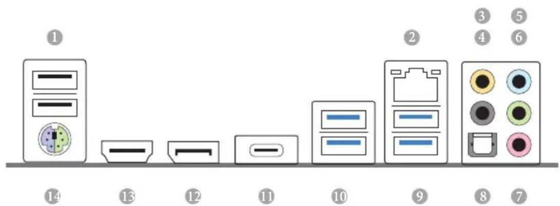
I/O Panel
text_image
Diagram showing a series of labeled electronic components or devices, with numbered labels 1 through 14 indicating different device categories.No. Description No. Description
1 USB 2.0 Ports (USB12) 8 Optical SPDIF Out Port
2 LAN RJ-45 Port* 9 USB 3.1 Gen1 Ports (USB3_1_2)
3 Central / Bass (Orange) 10 USB 3.1 Gen1 Ports (USB3_3_4)
4 Rear Speaker (Black) 11 USB 3.1 Gen1 Type-C Port (USB3_TC_1)
5 Line In (Light Blue) 12 DisplayPort 1.2
6 Front Speaker (Lime) ^** 13 HDMI Port
7 Microphone (Pink)
14 PS/2 Mouse/Keyboard Port
* There are two LEDs on each LAN port. Please refer to the table below for the LAN port LED indications.
Activity / Link LED Speed LED
Status Description Status Description
| Off No Link Off | 10Mbps connection | ||
| Blinking | Data Activity | Orange | 100Mbps connection |
| On Link Green | 1Gbps connection |
** If you use a 2-channel speaker, please connect the speaker's plug into "Front Speaker Jack". See the table below for connection details in accordance with the type of speaker you use.
| Audio Output Channels | Front Speaker (No.6) | Rear Speaker (No. 4) | Central / Bass (No. 3) | Line In (No. 5) |
| 2 V -- -- -- | ||||
| 4 V V -- -- | ||||
| 6 V V V -- | ||||
| 8 V V V V |
Chapter 1 Introduction
Thank you for purchasing ASRock B365M Phantom Gaming 4 motherboard, a reliable motherboard produced under ASRock's consistently stringent quality control. It delivers excellent performance with robust design conforming to ASRock's commitment to quality and endurance.

Because the motherboard specifications and the BIOS software might be updated, the content of this documentation will be subject to change without notice. In case any modifications of this documentation occur, the updated version will be available on ASRock's website without further notice. If you require technical support related to this motherboard, please visit our website for specific information about the model you are using. You may find the latest VGA cards and CPU support list on ASRock's website as well. ASRock website http://www.asrock.com.
1.1 Package Contents
ASRock B365M Phantom Gaming 4 Motherboard (Micro ATX Form Factor)
ASRock B365M Phantom Gaming 4 Quick Installation Guide
ASRock B365M Phantom Gaming 4 Support CD
1 x I/O Panel Shield
2 x Serial ATA (SATA) Data Cables (Optional)
3 x Screws for M.2 Socket (Optional)
1 x Standoff for M.2 Socket (Optional)
1.2 Specifications
| Platform | Micro ATX Form Factor |
| CPU | Supports 9^th and 8^th Gen Intel ^TM Processors (Socket 1151)Supports CPU up to 95WDigi Power design8 Power Phase designSupports Intel ^® Turbo Boost 2.0 Technology |
| Chipset | Intel ^® B365 |
| Memory | Dual Channel DDR4 Memory Technology4 x DDR4 DIMM SlotsSupports DDR4 2666/2400/2133 non-ECC, un-buffered memorySupports ECC UDIMM memory modules (operate in non-ECC mode)Supports Intel ^® Extreme Memory Profile (XMP) 2.015μ Gold Contact in DIMM Slots |
| Expansion Slot | 2 x PCI Express 3.0 x16 Slots (PCIE1/PCIE3: single at x16 (PCIE1); dual at x16 (PCIE1) / x4 (PCIE3))* Supports NVMe SSD as boot disks1 x PCI Express 3.0 x1 Slot (Flexible PCIe)Supports AMD Quad CrossFireX ^TM and CrossFireX ^TM 1 x M.2 Socket (Key E), supports type 2230 WiFi/BT module15μ Gold Contact in VGA PCIe Slot (PCIE1) |
| Graphics | Intel ^® UHD Graphics Built-in Visuals and the VGA outputs can be supported only with processors which are GPU integrated.Supports Intel ^® UHD Graphics Built-in Visuals : Intel ^® Quick Sync Video with AVC, MVC (S3D) and MPEG-2 Full HW Encode1, Intel ^® InTru ^TM 3D, Intel ^® Clear Video HD Technology, Intel ^® Insider ^TM , Intel ^® UHD Graphics DirectX 12 |
HWAEncode/Decode: AVC/H.264, HEVC/H.265 8-bit, HEVC/H.265 10-bit, VP8, VP9 8-bit, VP9 10-bit (Decode only), MPEG2, MJPEG, VC-1 (Decode only) Dual graphics outputs: HDMI and DisplayPort 1.2 Supports HDMI 1.4 with max. resolution up to 4K x 2K (4096x2160) @ 30Hz Supports DisplayPort 1.2 with max. resolution up to 4K x 2K (4096x2304) @ 60Hz Supports Auto Lip Sync, Deep Color (12bpc), xvYCC and HBR (High Bit Rate Audio) with HDMI 1.4 Port (Compliant HDMI monitor is required) Supports HDCP 2.2 with HDMI and DisplayPort 1.2 Ports Supports 4K Ultra HD (UHD) playback with HDMI and DisplayPort 1.2 Ports
Audio
7.1 CH HD Audio with Content Protection (Realtek ALC1200 Audio Codec) Premium Blu-ray Audio support Supports Surge Protection PCB Isolate Shielding Gold Audio Jacks Supports DTS Connect
LAN
Gigabit LAN 10/100/1000 Mb/s Giga PHY Intel® I219V Supports Wake-On-LAN Supports Lightning/ESD Protection Supports Energy Efficient Ethernet 802.3az Supports PXE
Rear Panel I/O
1 x PS/2 Mouse/Keyboard Port 1 x HDMI Port 1 x DisplayPort 1.2 1 x Optical SPDIF Out Port 2 x USB 2.0 Ports (Supports ESD Protection) 1 x USB 3.1 Gen1 Type-C Port (Supports ESD Protection) 4 x USB 3.1 Gen1 Ports (Supports ESD Protection)
1 x RJ-45 LAN Port with LED (ACT/LINK LED and SPEED LED) HD Audio Jacks: Rear Speaker / Central / Bass / Line in / Front Speaker / Microphone (Gold Audio Jacks)
Storage
6 x SATA3 6.0 Gb/s Connectors, support RAID (RAID 0, RAID 1, RAID 5, RAID 10, Intel Rapid Storage Technology 17), NCQ, AHCI and Hot Plug* * If M2_2 is occupied by a SATA-type M.2 device, SATA3_0 will be disabled. 1 x Ultra M.2 Socket (M2_1), supports M Key type 2242/2260/2280 M.2 PCI Express module up to Gen3 x4 (32 Gb/s)** 1 x Ultra M.2 Socket (M2_2), supports M Key type 2242/2260/2280/22110 M.2 SATA3 6.0 Gb/s module and M.2 PCI Express module up to Gen3 x4 (32 Gb/s)** ** Supports Intel® Optane™ Technology ** Supports NVMe SSD as boot disks ** Supports ASRock U.2 Kit
Connector
1 x COM Port Header 1 x TPM Header 1 x Chassis Intrusion and Speaker Header 2 x RGB LED Headers * Support in total up to 12V/3A, 36W LED Strip 1 x Addressable LED Header * Supports in total up to 5V/3A, 15W LED Strip 1 x CPU Fan Connector (4-pin) * The CPU Fan Connector supports the CPU fan of maximum 1A (12W) fan power. 1 x CPU/Water Pump Fan Connector (4-pin) (Smart Fan Speed Control) * The CPU/Water Pump Fan supports the water cooler fan of maximum 2A (24W) fan power. 3 x Chassis/Water Pump Fan Connectors (4-pin) (Smart Fan Speed Control) * The Chassis/Water Pump Fan supports the water cooler fan of maximum 2A (24W) fan power. * CPU_FAN2/WP, CHA_FAN1/WP, CHA_FAN2/WP and CHA_FAN3/WP can auto detect if 3-pin or 4-pin fan is in use.
| 1 x 24 pin ATX Power Connector1 x 8 pin 12V Power Connector1 x Front Panel Audio Connector2 x USB 2.0 Headers (Support 4 USB 2.0 ports) (Supports ESD Protection)1 x USB 3.1 Gen1 Header (Supports 2 USB 3.1 Gen1 ports) (Supports ESD Protection) | |
| BIOS Feature | AMI UEFI Legal BIOS with multilingual GUI supportACPI 6.0 Compliant wake up eventsSMBIOS 2.7 SupportCPU, GT, DRAM, PCH 1.0V, VCCIO , VCCSA, VCCSTVoltage Multi-adjustment |
| Hardware Monitor | Temperature Sensing: CPU, CPU/Water Pump, Chassis/Water Pump FansFan Tachometer: CPU, CPU/Water Pump, Chassis/Water Pump FansQuiet Fan (Auto adjust chassis fan speed by CPU temperature): CPU, CPU/Water Pump, Chassis/Water Pump FansFan Multi-Speed Control: CPU, CPU/Water Pump, Chassis/Water Pump FansVoltage monitoring: +12V, +5V, +3.3V, CPU Vcore, DRAM, VPPM, PCH 1.0V, VCCSA, VCCST |
| OS | Microsoft" Windows" 10 64-bit |
| Certifications | FCC, CEErP/EuP ready (ErP/EuP ready power supply is required) |
* For detailed product information, please visit our website: http://www.asrock.com

Please realize that there is a certain risk involved with overclocking, including adjusting the setting in the BIOS, applying Untied Overclocking Technology, or using third-party overclocking tools. Overclocking may affect your system's stability, or even cause damage to the components and devices of your system. It should be done at your own risk and expense. We are not responsible for possible damage caused by overclocking.
Chapter 2 Installation
This is a Micro ATX form factor motherboard. Before you install the motherboard, study the configuration of your chassis to ensure that the motherboard fits into it.
Pre-installation Precautions
Take note of the following precautions before you install motherboard components or change any motherboard settings.
Make sure to unplug the power cord before installing or removing the motherboard components. Failure to do so may cause physical injuries and damages to motherboard components.
In order to avoid damage from static electricity to the motherboard's components, NEVER place your motherboard directly on a carpet. Also remember to use a grounded wrist strap or touch a safety grounded object before you handle the components.
Hold components by the edges and do not touch the ICs.
Whenever you uninstall any components, place them on a grounded anti-static pad or in the bag that comes with the components.
When placing screws to secure the motherboard to the chassis, please do not over-tighten the screws! Doing so may damage the motherboard.
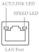
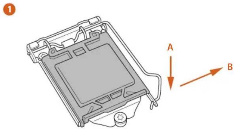
2.1 Installing the CPU

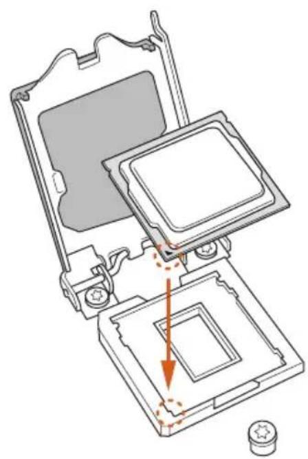
- Before you insert the 1151-Pin CPU into the socket, please check if the PnP cap is on the socket, if the CPU surface is unclean, or if there are any bent pins in the socket. Do not force to insert the CPU into the socket if above situation is found. Otherwise, the CPU will be seriously damaged.
- Unplug all power cables before installing the CPU.
text_image
1 A B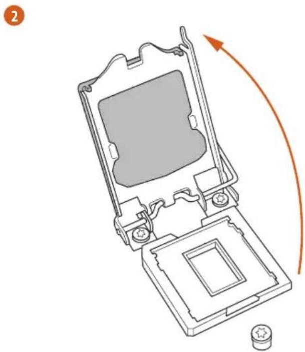
natural_image
Technical line drawing of a mechanical device with an arrow indicating rotation or assembly (no text or symbols present)3
natural_image
Technical diagram of a computer processor internal structure showing top and bottom views with no text or symbols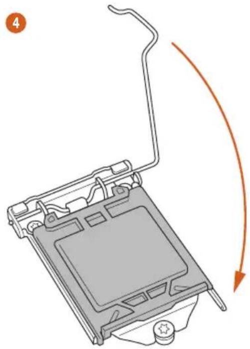
natural_image
Diagram of a computer monitor with an orange curved arrow indicating motion or rotation (no text or symbols present)5
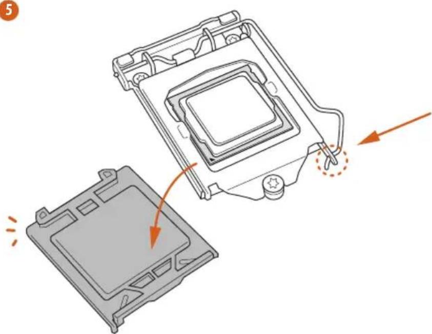
natural_image
Diagram showing a computer processor's internal structure and external casing, with arrows indicating motion (no text or symbols)
Please save and replace the cover if the processor is removed. The cover must be placed if you wish to return the motherboard for after service.
2.2 Installing the CPU Fan and Heatsink
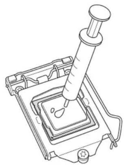
natural_image
Line drawing of a pipette dispensing liquid into a square container (no text or symbols)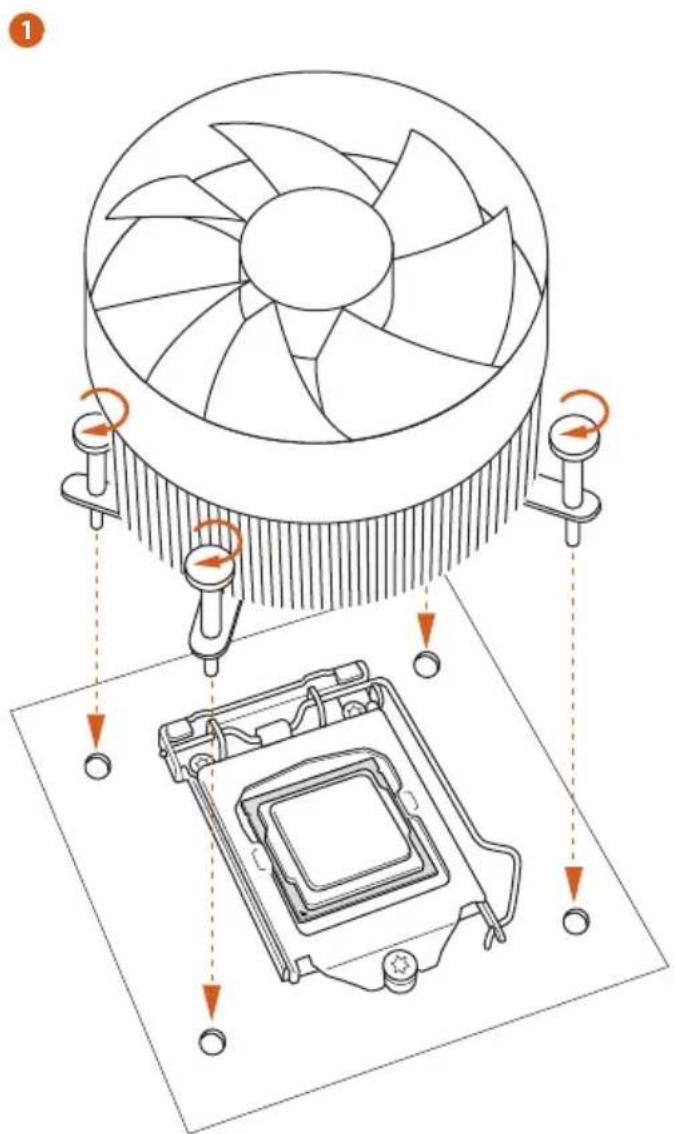
text_image
Technical diagram showing CPU cooling system with fan and heatsink components, annotated with rotation arrows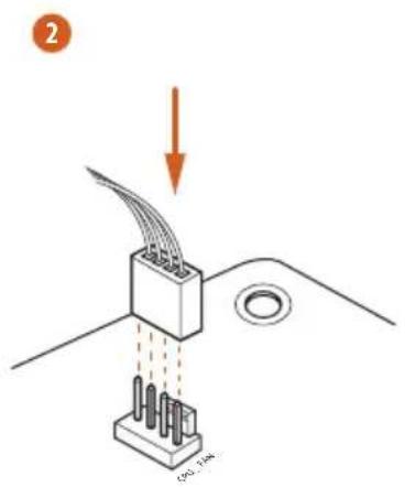
text_image
2 190.3.3kV
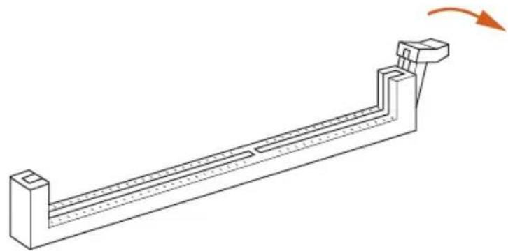
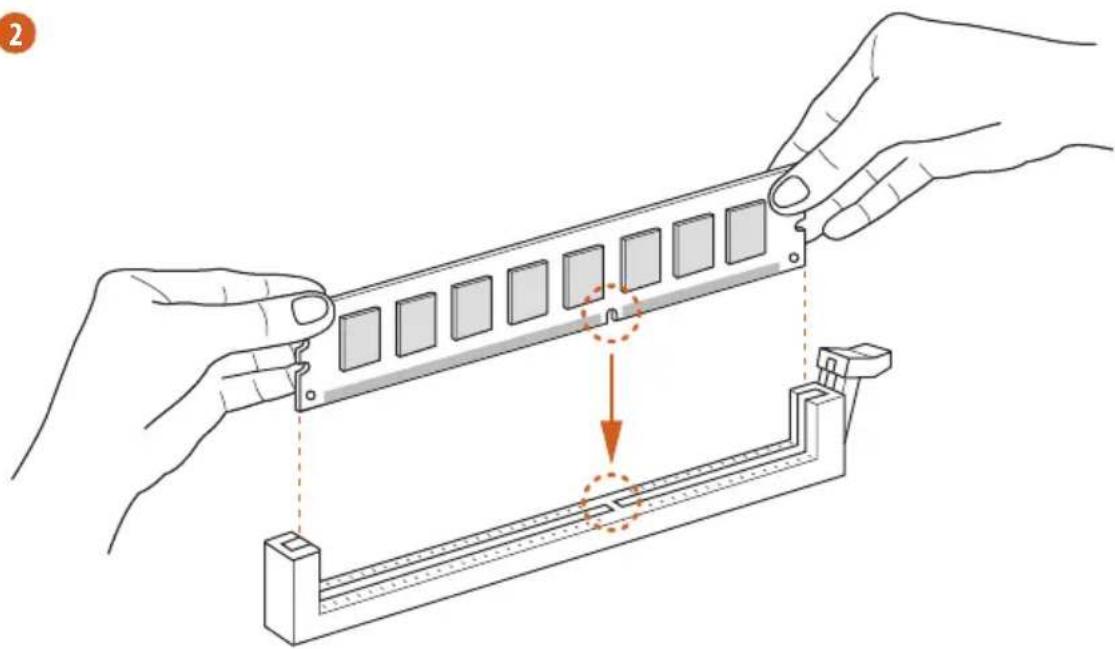
2.3 Installing Memory Modules (DIMM)
This motherboard provides four 288-pin DDR4 (Double Data Rate 4) DIMM slots, and supports Dual Channel Memory Technology.

- For dual channel configuration, you always need to install identical (the same brand, speed, size and chip-type) DDR4 DIMM pairs.
- It is unable to activate Dual Channel Memory Technology with only one or three memory module installed.
- It is not allowed to install a DDR, DDR2 or DDR3 memory module into a DDR4 slot; otherwise, this motherboard and DIMM may be damaged.
Dual Channel Memory Configuration
Priority DDR4_A1 DDR4_A2 DDR4_B1 DDR4_B2
| 1 Populated Populated | |||
| 2 Populated Populated Populated Populated |

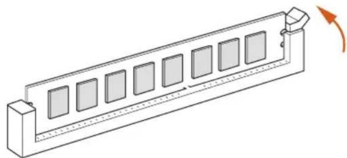
The DIMM only fits in one correct orientation. It will cause permanent damage to the motherboard and the DIMM if you force the DIMM into the slot at incorrect orientation.
1
natural_image
Technical line drawing of a mechanical support structure with an arrow indicating rotation (no text or symbols)2
natural_image
Illustration of hands installing a component into a mechanical bracket with an arrow indicating the process (no text or symbols present)3
natural_image
Isometric line drawing of a rectangular electronic component with multiple square slots and a curved arrow indicating rotation (no text or symbols)2.4 Expansion Slots (PCI Express Slots)
There are 3 PCI Express slots on the motherboard.

Before installing an expansion card, please make sure that the power supply is switched off or the power cord is unplugged. Please read the documentation of the expansion card and make necessary hardware settings for the card before you start the installation.
PCIe slots:
PCIE1 (PCIe 3.0 x16 slot) is used for PCI Express x16 lane width graphics cards. PCIE2 (PCIe 3.0 x1 slot) is used for PCI Express x1 lane width cards. PCIE3 (PCIe 3.0 x16 slot) is used for PCI Express x4 lane width graphics cards.
PCIe Slot Configurations
PCIE1 PCIE3
Single Graphics Card x16 N/A
Two Graphics Cards in CrossFireX™ Mode
x16 x4

For a better thermal environment, please connect a chassis fan to the motherboard's chassis fan connector (CHA_FAN1/WP, CHA_FAN2/WP or CHA_FAN3/WP) when using multiple graphics cards.
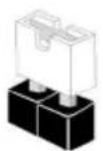
2.5 Jumpers Setup
The illustration shows how jumpers are setup. When the jumper cap is placed on the pins, the jumper is "Short". If no jumper cap is placed on the pins, the jumper is "Open".
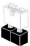
Short
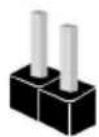
Open
Clear CMOS Jumper
(CLRCMOS1)
(see p.1, No. 23)

2-pin Jumper
Short: Clear CMOS
Open: Default
CLRCMOS1 allows you to clear the data in CMOS. The data in CMOS includes system setup information such as system password, date, time, and system setup parameters. To clear and reset the system parameters to default setup, please turn off the computer and unplug the power cord, then use a jumper cap to short the pins on CLRCMOS1 for 3 seconds. Please remember to remove the jumper cap after clearing the CMOS. If you need to clear the CMOS when you just finish updating the BIOS, you must boot up the system first, and then shut it down before you do the clear-CMOS action.
2.6 Onboard Headers and Connectors

Onboard headers and connectors are NOT jumpers. Do NOT place jumper caps over these headers and connectors. Placing jumper caps over the headers and connectors will cause permanent damage to the motherboard.
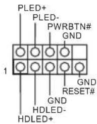
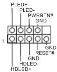
System Panel Header (9-pin PANEL1) (see p.1, No. 14)
text_image
PLED+ PLED- PWRBTN# GND 1 GND RESET# GND HDLED- HDLED+Connect the power button, reset button and system status indicator on the chassis to this header according to the pin assignments below. Note the positive and negative pins before connecting the cables.

PWRBTN (Power Button):
Connect to the power button on the chassis front panel. You may configure the way to turn off your system using the power button.
RESET (Reset Button):
Connect to the reset button on the chassis front panel. Press the reset button to restart the computer if the computer freezes and fails to perform a normal restart.
PLED (System Power LED):
Connect to the power status indicator on the chassis front panel. The LED is on when the system is operating. The LED keeps blinking when the system is in S1/S3 sleep state. The LED is off when the system is in S4 sleep state or powered off (S5).
HDLED (Hard Drive Activity LED):
Connect to the hard drive activity LED on the chassis front panel. The LED is on when the hard drive is reading or writing data.
The front panel design may differ by chassis. A front panel module mainly consists of power button, reset button, power LED, hard drive activity LED, speaker and etc. When connecting your chassis front panel module to this header, make sure the wire assignments and the pin assignments are matched correctly.
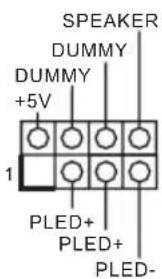
Power LED and Speaker Header
(7-pin SPK_PLED1)
(see p.1, No. 12)
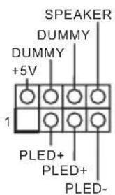
Please connect the chassis power LED and the chassis speaker to this header.
Serial ATA3 Connectors
(SATA3_0:
see p.1, No. 15)
(SATA3_1:
see p.1, No. 16)
(SATA3_2_3:
see p.1, No. 10)
(SATA3_4_5:
see p.1, No. 11)
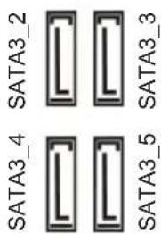
text_image
SATA3_4 SATA3_2 SATA3_3 SATA3_5These six SATA3 connectors support SATA data cables for internal storage devices with up to 6.0 Gb/s data transfer rate. * If M2_2 is occupied by a SATA-type M.2 device,
SATA3_0SATA3_\$ATA3_0 will be disabled.

USB 2.0 Headers
(9-pin USB3_4)
(see p.1, No. 18)
(9-pin USB5_6)
(see p.1, No. 17)
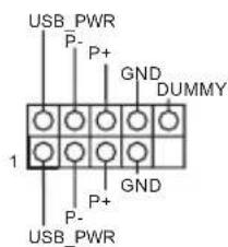
text_image
USB PWR P- P+ GND DUMMY 1 GND P- P+ USB PWRThere are two headers on this motherboard. Each USB 2.0 header can support two ports.
USB 3.1 Gen1 Header
(19-pin USB3_5_6)
(see p.1, No. 8)
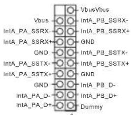
text_image
Vbus IntA_PA_SSRX IntA_PA_SSRX+ GND IntA_PA_SSTX- IntA_PA_SSTX+ GND IntA_PA_D- IntA_PA_D+ VbusVbus IntA_PB_SSRX- IntA_PB_SSRX+ GND IntA_PB_SSTX- IntA_PB_SSTX+ GND IntA_PB_D- IntA_PB_D+ DummyThere is one header on this motherboard. This USB 3.1 Gen1 header can support two ports.
Front Panel Audio Header
(9-pin HD_AUDIO1)
(see p.1, No. 25)
text_image
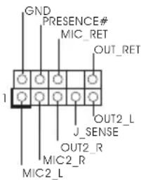
GND PRESENCE# MIC_RET OUT_RET J_SENSE OUT2_L J_SENSE OUT2_R MIC2_R MIC2_LThis header is for
connecting audio devices
to the front audio panel.

- High Definition Audio supports Jack Sensing, but the panel wire on the chassis must support HDA to function correctly. Please follow the instructions in our manual and chassis manual to install your system.
- If you use an AC'97 audio panel, please install it to the front panel audio header by the steps below:
A. Connect Mic_IN (MIC) to MIC2_L.
B. Connect Audio_R (RIN) to OUT2_R and Audio_L (LIN) to OUT2_L.
C. Connect Ground (GND) to Ground (GND).
D. MIC_RET and OUT_RET are for the HD audio panel only. You don't need to connect them for the AC'97 audio panel.
E. To activate the front mic, go to the "FrontMic" Tab in the Realtek Control panel and adjust "Recording Volume".
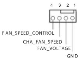
Chassis/Water Pump Fan
Connectors
(4-pin CHA_FAN1/WP)
(see p.1, No. 26)
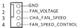
This motherboard
provides three 4-Pin water cooling chassis fan connectors. If you plan to connect a 3-Pin chassis water cooler fan, please connect it to Pin 1-3.
(4-pin CHA_FAN2/WP)
(see p.1, No. 19)
(4-pin CHA_FAN3/WP)
(see p.1, No. 20)
text_image
4 3 2 1 FAN_SPEED_CONTROL CHA_FAN_SPEED FAN_VOLTAGE GN DCPU Fan Connector
(4-pin CPU_FAN1)
(see p.1, No. 2)
This motherboard
provides a 4-Pin CPU fan (Quiet Fan) connector.
If you plan to connect a 3-Pin CPU fan, please connect it to Pin 1-3.
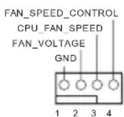
CPU/Water Pump Fan Connector (4-pin CPU_FAN2/WP) (see p.1, No. 5)
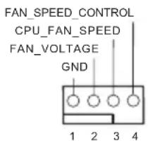
text_image
FAN_SPEED_CONTROL CPU_FAN_SPEED FAN_VOLTAGE GND 1 2 3 4This motherboard provides a 4-Pin water cooling CPU fan connector. If you plan to connect a 3-Pin CPU water cooler fan, please connect it to Pin 1-3.
ATX Power Connector (24-pin ATXPWR1) (see p.1, No. 7)
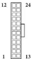
This motherboard provides a 24-pin ATX power connector. To use a 20-pin ATX power supply, please plug it along Pin 1 and Pin 13.
ATX 12V Power Connector (8-pin ATX12V1) (see p.1, No. 1)
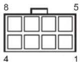
This motherboard provides an 8-pin ATX 12V power connector. To use a 4-pin ATX power supply, please plug it along Pin 1 and Pin 5.
Serial Port Header (9-pin COM1) (see p.1, No. 24)
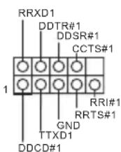
This COM1 header supports a serial port module.
TPM Header (17-pin TPMS1) (see p.1, No. 21)
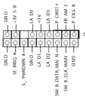
text_image
GN D +3V S B SE RIRQ # S_ PWRDWN # GN D LA D0 LA D1 LA D2 LA D3 P CIRST# FR AM E P CICL K SM B_DATA MAIN N SM B_CLK MAIN QNDThis connector supports Trusted Platform Module (TPM) system, which can securely store keys, digital certificates, passwords, and data. A TPM system also helps enhance network security, protects digital identities, and ensures platform integrity.
RGB LED Headers
(4-pin RGB_LED1)
(see p.1, No. 22)
(4-pin RGB_LED2)
(see p.1, No. 9)
These two RGB headers are used to connect RGB LED extension cable which allows users to choose from various LED lighting effects.
Caution: Never install the RGB LED cable in the wrong orientation; otherwise, the cable may be damaged.
*Please refer to page 35 for further instructions on this header.
Addressable LED Header
(3-pin A_RGB_LED1)
(see p.1, No. 6)
This header is used to connect Addressable LED extension cable which allows users to choose from various LED lighting effects.
Caution: Never install the Addressable LED cable in the wrong orientation; otherwise, the cable may be damaged.
*Please refer to page 36 for further instructions on this header.
2.7 Post Status Checker
Post Status Checker (PSC) diagnoses the computer when users power on the machine. It emits a red light to indicate whether the CPU, memory, VGA or storage is dysfunctional. The lights go off if the four mentioned above are functioning normally.
2.8 M.2 WiFi/BT Module Installation Guide
The M.2, also known as the Next Generation Form Factor (NGFF), is a small size and versatile card edge connector that aims to replace mPCIe and mSATA. The M.2 Socket (Key E) supports type 2230 WiFi/BT module.
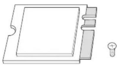
Installing the WiFi/BT module
natural_image
Pure technical line drawing of a mechanical component with no text or symbolsStep 1
Prepare a type 2230 WiFi/BT module and the screw.
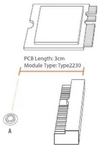
text_image
PCB Length: 3cm Module Type: Type2230 AStep 2
Find the nut location to be used.
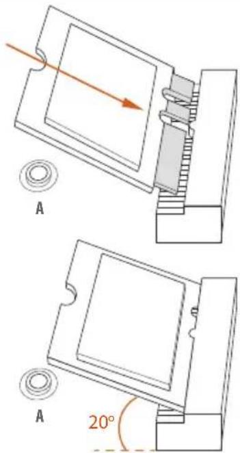
text_image
A A 20°Step 3
Gently insert the WiFi/BT module into the M.2 slot. Please be aware that the module only fits in one orientation.
natural_image
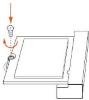
Diagram showing a light bulb interacting with a rectangular panel, with an arrow indicating motion (no text or symbols present)Step 4
Tighten the screw with a screwdriver to secure the module into place. Please do not overtighten the screw as this might damage the module.
2.9 M.2\_SSD (NGFF) Module Installation Guide (M2\_1)
The M.2, also known as the Next Generation Form Factor (NGFF), is a small size and versatile card edge connector that aims to replace mPCIe and mSATA. The Ultra M.2 Socket (M2_1) supports M Key type 2242/2260/2280 M.2 PCI Express module up to Gen3 x4 (32 Gb/s).
natural_image
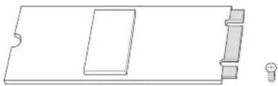
Pure technical line drawing of a rectangular component with a slot and two small components (no text or symbols)Step 1
Prepare a M.2_SSD (NGFF) module and the screw.
text_image
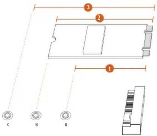
C B A 1 2 3Step 2
Depending on the PCB type and length of your M.2_SSD (NGFF) module, find the corresponding nut location to be used.
No.123
Nut Location A B C
PCB Length 4.2cm 6cm 8cm
Module Type
Type 2242
Type2260
Type 2280
text_image
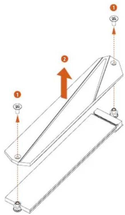
Technical diagram of a mechanical component with numbered parts and directional arrows indicating assembly or movement.Step 3
Before installing a M.2 (NGFF) SSD module, please loosen the screws to remove the M.2 heatsink.

text_image
C B A C B A 20°Step 4
Prepare the M.2 standoff that comes with the package. Then hand tighten the standoff into the desired nut location on the motherboard. Align and gently insert the M.2 (NGFF) SSD module into the M.2 slot. Please be aware that the M.2 (NGFF) SSD module only fits in one orientation.
natural_image
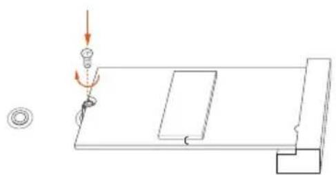
Pure technical diagram showing a mechanical assembly with no text, numbers, or symbolsStep 5
Tighten the screw with a screwdriver to secure the module into place. Please do not overtighten the screw as this might damage the module.
M.2\_SSD (NGFF) Module Support List
| Vendor Interface Length P/N | |||
| ADATA PCIe3 x4 2280 ASX7000NP-128GT-C | |||
| ADATA PCIe3 x4 2280 ASX8000NP-256GM-C | |||
| ADATA PCIe3 x4 2280 ASX7000NP-256GT-C | |||
| ADATA PCIe3 x4 2280 ASX7000NP-512GT-C | |||
| ADATA PCIe3 x4 2280 ASX8000NP-512GM-C | |||
| Corsair PCIe3 x4 2280 CSSD-F240GBMP500 | |||
| Intel PCIe3 x4 2280 SSDPEKKF256G7 | |||
| Intel PCIe3 x4 2280 SSDPEKKF512G7 | |||
| Kingston PCIe2 x4 2280 SH2280S3/480G | |||
| OCZ PCIe3 x4 2280 RVD400 -M2280-512G (NVME) | |||
| Plextor PCIe3 x4 2280 PX-128M8PeG | |||
| Plextor PCIe3 x4 2280 PX-1TM8PeG | |||
| Plextor PCIe3 x4 2280 PX-256M8PeG | |||
| Plextor PCIe3 x4 2280 PX-512M8PeG | |||
| Plextor PCIe 2280 PX-G256M6e | |||
| Plextor PCIe 2280 PX-G512M6e | |||
| Samsung | PCIe3 x4 | 2280 | SM961 MZVPW128HEGM (NVM) |
| Samsung | PCIe3 x4 | 2280 | PM961 MZVLW128HEGR (NVME) |
| Samsung | PCIe3 x4 | 2280 | 960 EVO (MZ-V6E250) (NVME) |
| Samsung | PCIe3 x4 | 2280 | 960 EVO (MZ-V6E250BW) (NVME) |
| Samsung PCIe3 x4 2280 SM951 (NVME) | |||
| Samsung | PCIe3 x4 | 2280 | SM951 (MZHPV256HDGL) |
| Samsung | PCIe3 x4 | 2280 | SM951 (MZHPV512HDGL) |
| Samsung PCIe3 x4 2280 SM951 (NVME) | |||
| Samsung | PCIe x4 | 2280 | XP941-512G (MZHPU512HCGL) |
| SanDisk | PCIe | 2260 | SD6PP4M-128G |
| SanDisk | PCIe | 2260 | SD6PP4M-256G |
| TEAM | PCIe3 x4 | 2280 | TM8FP2240G0C101 |
| TEAM | PCIe3 x4 | 2280 | TM8FP2480GC110 |
| WD | PCIe3 x4 | 2280 | WDS256G1X0C-00ENX0 (NVME) |
| WD | PCIe3 x4 | 2280 | WDS512G1X0C-00ENX0 (NVME) |
For the latest updates of M.2_SSD (NFGG) module support list, please visit our website for details: http://www.asrock.com
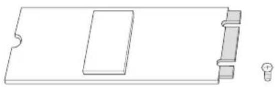
2.10 M.2\_SSD (NGFF) Module Installation Guide (M2\_2)
The M.2, also known as the Next Generation Form Factor (NGFF), is a small size and versatile card edge connector that aims to replace mPCIe and mSATA. The Ultra M.2 Socket (M2_2) supports M Key type 2242/2260/2280/22110 M.2 SATA3 6.0 Gb/s module and M.2 PCI Express module up to Gen3 x4 (32 Gb/s).
* If M2_2 is occupied by a SATA-type M.2 device, SATA3_0 will be disabled.
Installing the M.2\_SSD (NGFF) Module
natural_image
Pure technical line drawing of a rectangular component with a recessed slot and two side connectors (no text or symbols)Step 1
Prepare a M.2_SSD (NGFF) module and the screw.
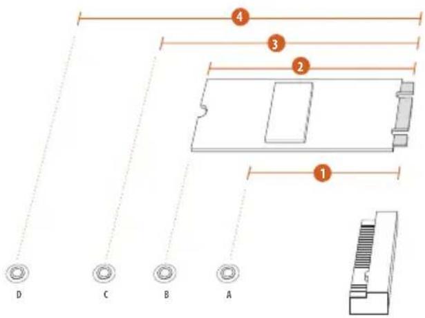
text_image
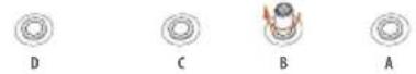
4 3 2 1 D C B AStep 2
Depending on the PCB type and length of your M.2_SSD (NGFF) module, find the corresponding nut location to be used.
No.1234
| Nut Location A B C D | ||||
| PCB Length | 4.2cm | 6cm | 8cm | 11cm |
| Module Type | Type 2242 | Type2260 | Type 2280 | Type 22110 |
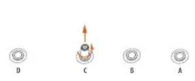
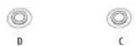
natural_image
Four circular diagrams labeled A, B, C, D showing different mechanical or electrical components with directional arrows (no text or symbols beyond labels)
Step 3
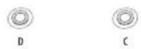
Move the standoff based on the module type and length. The standoff is placed at the nut location C by default. Skip Step 3 and 4 and go straight to Step 5 if you are going to use the default nut. Otherwise, release the standoff by hand.
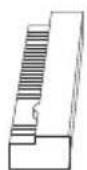
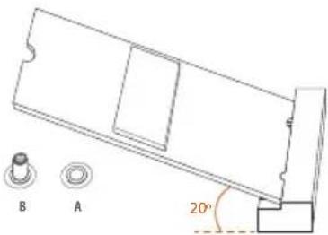
Step 4
Peel off the yellow protective film on the nut to be used. Hand tighten the standoff into the desired nut location on the motherboard.
natural_image
Technical diagram of a mechanical assembly with labeled parts A and B, showing internal components and directional arrow (no text or symbols beyond labels)Step 5
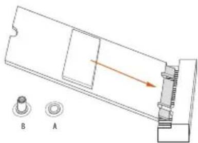
Align and gently insert the M.2 (NGFF) SSD module into the M.2 slot. Please be aware that the M.2 (NGFF) SSD module only fits in one orientation.
natural_image
Technical line drawing of a mechanical part with two circular features labeled A and B, and a 20° angle indicator (no text or symbols beyond labels)
natural_image
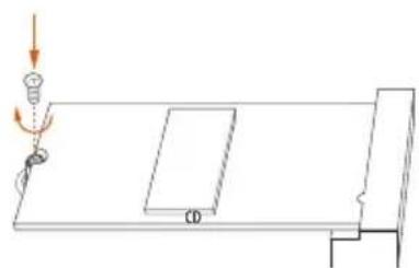
Simple line drawing of a lamp on a table with a CD label, no text or symbols presentStep 6
Tighten the screw with a screwdriver to secure the module into place. Please do not overtighten the screw as this might damage the module.
M.2\_SSD (NGFF) Module Support List
| Vendor Interface Length P/N | |||
| ADATA SATA3 2280 AXNS381E-128GM-B | |||
| ADATA SATA3 2280 ASU800NS38-256GT-C | |||
| ADATA SATA3 2280 AXNS381E-256GM-B | |||
| ADATA SATA3 2280 ASU800NS38-512GT-C | |||
| ADATA PCIe3 x4 2280 ASX7000NP-128GT-C | |||
| ADATA PCIe3 x4 2280 ASX8000NP-256GM-C | |||
| ADATA PCIe3 x4 2280 ASX7000NP-256GT-C | |||
| ADATA PCIe3 x4 2280 ASX7000NP-512GT-C | |||
| ADATA PCIe3 x4 2280 ASX8000NP-512GM-C | |||
| Corsair PCIe3 x4 2280 CSSD-F240GBMP500 | |||
| Crucial SATA3 2280 CT120M500SSD4 | |||
| Crucial SATA3 2280 CT240M500SSD4 | |||
| Intel SATA3 2280 Intel SSDSCKGW080A401/80G | |||
| Intel PCIe3 x4 2280 SSDPEKKF256G7 | |||
| Intel PCIe3 x4 2280 SSDPEKKF512G7 | |||
| Kingston SATA3 2280 SM2280S3 | |||
| Kingston PCIe2 x4 2280 SH2280S3/480G | |||
| OCZ PCIe3 x4 2280 RVD400 -M2280-512G (NVME) | |||
| Plextor | PCIe3 x4 | 2280 | PX-128M8PeG |
| Plextor | PCIe3 x4 | 2280 | PX-1TM8PeG |
| Plextor | PCIe3 x4 | 2280 | PX-256M8PeG |
| Plextor | PCIe3 x4 | 2280 | PX-512M8PeG |
| Plextor | PCIe | 2280 | PX-G256M6e |
| Plextor | PCIe | 2280 | PX-G512M6e |
| Samsung | PCIe3 x4 | 2280 | SM961 MZVPW128HEGM (NVM) |
| Samsung | PCIe3 x4 | 2280 | PM961 MZVLW128HEGR (NVME) |
| Samsung | PCIe3 x4 | 2280 | 960 EVO (MZ-V6E250) (NVME) |
| Samsung | PCIe3 x4 | 2280 | 960 EVO (MZ-V6E250BW) (NVME) |
| Samsung | PCIe3 x4 | 2280 | SM951 (NVME) |
| Samsung | PCIe3 x4 | 2280 | SM951 (MZHPV256HDGL) |
| Samsung | PCIe3 x4 | 2280 | SM951 (MZHPV512HDGL) |
| Samsung | PCIe3 x4 | 2280 | SM951 (NVME) |
| Samsung | PCIe x4 | 2280 XP941-512G (MZHPU512HCGL) | |
| SanDisk | PCIe | 2260 | SD6PP4M-128G |
| SanDisk | PCIe | 2260 | SD6PP4M-256G |
| Team SATA3 2242 TM4PS4128GMC105 | |||
| Team SATA3 2242 TM4PS4256GMC105 | |||
| Team SATA3 2280 TM8PS4128GMC105 | |||
| Team SATA3 2280 TM8PS4256GMC105 | |||
| TEAM | PCIe3 x4 | 2280 | TM8FP2240G0C101 |
| TEAM | PCIe3 x4 | 2280 | TM8FP2480GC110 |
| Transcend | SATA3 | 2242 | TS256GMTS400 |
| Transcend SATA3 2260 TS512GMTS600 | |||
| Transcend SATA3 2280 TS512GMTS800 | |||
| V-Color SATA3 2280 VLM100-120G-2280B-RD | |||
| V-Color SATA3 2280 VLM100-240G-2280B-RD | |||
| V-Color SATA3 2280 VLM100-240G-2280RGB | |||
| V-Color SATA3 2280 VSM100-240G-2280 | |||
| WD SATA3 2280 WDS100T1B0B-00AS40 | |||
| WD SATA3 2280 WDS240G1G0B-00RC30 | |||
| WD | PCIe3 x4 | 2280 | WDS256G1X0C-00ENX0 (NVME) |
| WD | PCIe3 x4 | 2280 | WDS512G1X0C-00ENX0 (NVME) |
For the latest updates of M.2_SSD (NFGG) module support list, please visit our website for details: http://www.asrock.com
2.11 ASRock RGB LED
ASRock RGB LED is a lighting control utility specifically designed for unique individuals with sophisticated tastes to build their own stylish colorful lighting system. Simply by connecting the LED strip, you can customize various lighting schemes and patterns, including Static, Breathing, Strobe, Cycling, Music, Wave and more.
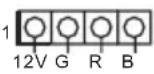
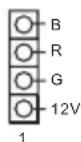
Connecting the LED Strip
Connect your RGB LED strips to the RGB LED Headers (RGB_LED1, RGB_LED2) on the motherboard.
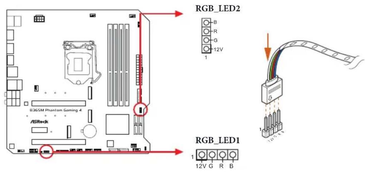
text_image
RGB_LED2 B R G 12V 1 B36SM Phantom Gaming 4 ASRock RGB_LED1 1 12V G R B
- Never install the RGB LED cable in the wrong orientation; otherwise, the cable may be damaged.
- Before installing or removing your RGB LED cable, please power off your system and unplug the power cord from the power supply. Failure to do so may cause damages to motherboard components.

- Please note that the RGB LED strips do not come with the package.
- The RGB LED header supports standard 5050 RGB LED strip (12V/G/R/B), with a maximum power rating of 3A (12V) and length within 2 meters.
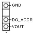
Connecting the Addressable RGB LED Strip
Connect your Addressable RGB LED strip to the Addressable LED Header (ADDR_LED1) on the motherboard.
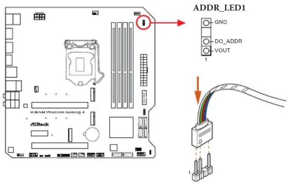
text_image
ADDR_LED1 GND DO_ADDR VOUT 1 B36SM Phantom Gaming 4 ASRock
- Never install the RGB LED cable in the wrong orientation; otherwise, the cable may be damaged.
- Before installing or removing your RGB LED cable, please power off your system and unplug the power cord from the power supply. Failure to do so may cause damages to motherboard components.

- Please note that the RGB LED strips do not come with the package.
- The RGB LED header supports WS2812B addressable RGB LED strip (5V/Data/GND), with a maximum power rating of 3A (5V) and length within 2 meters.
ASRock RGB LED Utility
Now you can adjust the RGB LED color through the ASRock RGB LED utility. Download this utility from the ASRock Live Update & APP Shop and start coloring your PC style your way!
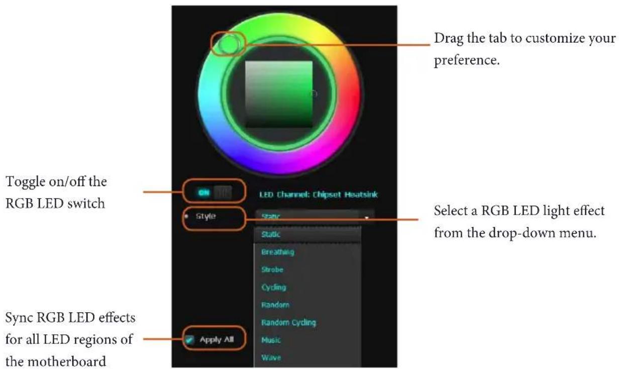
text_image
Drag the tab to customize your preference. Toggle on/off the RGB LED switch Style LED Channel: Chipset Heatsink Select a RGB LED light effect from the drop-down menu. Sync RGB LED effects for all LED regions of the motherboard Apply All1 Einleitung
ASRock B365M Phantom Gaming 4-Support-CD
Serial-ATA-III-Anschlüsse
(4-polig, CHA_FAN1/WP)
(4-polig, CHA_FAN2/WP)
(4-polig, CHA_FAN3/WP)
Scheda madre ASRock B365M Phantom Gaming 4 (Form Factor Micro ATX)
6 x connettori SATA3 6,0 Gb/s, supportano RAID (RAID 0, RAID 1, RAID 5, RAID 10, Intel Rapid Storage Technology 17), NCQ, AHCI e Hot Plug*
** Supporta kit ASRock U.2
Connettore
Placa Mãe ASRock B365M Phantom Gaming 4 (Micro ATX Form Factor)
PCH 1.0V, VCCSA, VCCST
os
인증
natural_image
Blank white image with no visible content, text, or symbols| TM | TM |
text_image
TM TM(4096x2160) @ 30Hz
(4096x2304) @ 60Hz
LAN
** Intel® Optane™
os

1.3 ジャンパー設定
Short
Open
(CLRCMOS1)

1.4 オンボードのヘッダーとコネクタ

text_image
PLED+ PLED- PWRBTN# GND 1 GND RESET# GND HDLED- HDLED+
If you need to contact ASRock or want to know more about ASRock, you're welcome to visit ASRock's website at http://www.asrock.com; or you may contact your dealer for further information. For technical questions, please submit a support request form at https://event.asrock.com/tsd.asp
ASRock Incorporation
2F., No.37, Sec. 2, Jhongyang S. Rd., Beitou District,
Taipei City 112, Taiwan (R.O.C.)
ASRock EUROPE B.V.
Bijsterhuizen 11-11
6546 AR Nijmegen
The Netherlands
Phone: +31-24-345-44-33
Fax: +31-24-345-44-38
ASRock America, Inc.
13848 Magnolia Ave, Chino, CA91710
U.S.A.
Phone: +1-909-590-8308
Fax: +1-909-590-1026
DECLARATION OF CONFORMITY
Per FCC Part 2 Section 2.1077(a)

Responsible Party Name: ASRock Incorporation
Address: 13848 Magnolia Ave, Chino, CA91710
Phone/Fax N o: +1-909-590-8308/+1-909-590-1026
hereby declares that the product
Product Name : Motherboard
Model Number : B365M Phantom Gaming 4
Conforms to the following specifications:
☒ FCC Part 15, Subpart B, Unintentional Radiators
Supplementary Information:
This device complies with part 15 of the FCC Rules. Operation is subject to the following two conditions: (1) This device may not cause harmful interference, and (2) this device must accept any interference received, including interference that may cause undesired operation.
Representative Person's Name: James
Signature :

Date : May 12, 2017
EU Declaration of Conformity
ASRock®
For the following equipment:
Motherboard
(Product Name)
B365M Phantom Gaming 4 / ASRock
(Model Designation / Trade Name)
ASRock Incorporation
(Manufacturer Name)
2F., No.37, Sec. 2, Jhongyang S. Rd., Beitou District, Taipei City 112, Taiwan (R.O.C.)
(Manufacturer Address)
EMC — Directive 2014/30/EU (from April 20th, 2016)
□ EN 55022:2010/AC:2011 Class B
EN 55024:2010/A1:2015
EN 61000-3-3:2013
□ LVD — Directive 2014/35/EU (from April 20th, 2016)
□ EN 60950-1:2011+A2:2013
□ EN 60950-1:2006/A12:2011
— Directive 2011/65/EU
(EU conformity marking)
CE
ASRock EUROPE B.V.
(Company Name)
Bijsterhuizen 1111 6546 AR Nijmegen The Netherlands
(Company Address)
Person responsible for making this declaration:

(Name, Surname)
A.V.P
(Position / Title)
January 25, 2019
(Date)
P/N: 15G062145000AK V1.0