X570 Phantom Gaming X - Motherboard ASROCK - Free user manual and instructions
Find the device manual for free X570 Phantom Gaming X ASROCK in PDF.

User questions about X570 Phantom Gaming X ASROCK
0 question about this device. Answer the ones you know or ask your own.
Ask a new question about this device
Download the instructions for your Motherboard in PDF format for free! Find your manual X570 Phantom Gaming X - ASROCK and take your electronic device back in hand. On this page are published all the documents necessary for the use of your device. X570 Phantom Gaming X by ASROCK.
USER MANUAL X570 Phantom Gaming X ASROCK
Copyright©2019 ASRock INC. All rights reserved.
Copyright Notice:
No part of this documentation may be reproduced, transcribed, transmitted, or translated in any language, in any form or by any means, except duplication of documentation by the purchaser for backup purpose, without written consent of ASRock Inc.
Products and corporate names appearing in this documentation may or may not be registered trademarks or copyrights of their respective companies, and are used only for identification or explanation and to the owners' benefit, without intent to infringe.
Disclaimer:
Specifications and information contained in this documentation are furnished for informational use only and subject to change without notice, and should not be constructed as a commitment by ASRock. ASRock assumes no responsibility for any errors or omissions that may appear in this documentation.
With respect to the contents of this documentation, ASRock does not provide warranty of any kind, either expressed or implied, including but not limited to the implied warranties or conditions of merchantability or fitness for a particular purpose.
In no event shall ASRock, its directors, officers, employees, or agents be liable for any indirect, special, incidental, or consequential damages (including damages for loss of profits, loss of business, loss of data, interruption of business and the like), even if ASRock has been advised of the possibility of such damages arising from any defect or error in the documentation or product.

This device complies with Part 15 of the FCC Rules. Operation is subject to the following two conditions:
(1) this device may not cause harmful interference, and
(2) this device must accept any interference received, including interference that may cause undesired operation.
CALIFORNIA, USA ONLY
The Lithium battery adopted on this motherboard contains Perchlorate, a toxic substance controlled in Perchlorate Best Management Practices (BMP) regulations passed by the California Legislature. When you discard the Lithium battery in California, USA, please follow the related regulations in advance.
"Perchlorate Material-special handling may apply, see www.dtsc.ca.gov/hazardouswaste/perchlorate"
ASRock Website: http://www.asrock.com

AUSTRALIA ONLY
Our goods come with guarantees that cannot be excluded under the Australian Consumer Law. You are entitled to a replacement or refund for a major failure and compensation for any other reasonably foreseeable loss or damage caused by our goods. You are also entitled to have the goods repaired or replaced if the goods fail to be of acceptable quality and the failure does not amount to a major failure. If you require assistance please call ASRock Tel : +886-2-28965588 ext.123 (Standard International call charges apply)
The terms HDMI ^* and HDMI High-Definition Multimedia Interface, and the HDMI logo are trademarks or registered trademarks of HDMI Licensing LLC in the United States and other countries.

HIGH-DEFINITION MULTIMEDIA INTERFACE
CE Warning
This device complies with directive 2014/53/EU issued by the Commission of the European Community.
This equipment complies with EU radiation exposure limits set forth for an uncontrolled environment.
This equipment should be installed and operated with minimum distance 20cm between the radiator & your body.
Operations in the 5.15-5.35GHz band are restricted to indoor usage only.
| AT | BE | BG | CH | CY | CZ | DE | |
| DK | EE | EL | ES | FI | FR | HR | |
| HU | IE | IS | IT | LI | LT | LU | |
| LV | MT | NL | NO | PL | PT | RO | |
| SE | SI | SK | TR | UK |

Radio transmit power per transceiver type
Function Frequency Maximum Output Power (EIRP)
| 2400-2483.5 MHz 18.5 + / -1.5 dbm | ||
| 5150-5250 MHz 21.5 + / -1.5 dbm | ||
| WiFi | 5250-5350 MHz | 18.5 + / -1.5 dbm (no TPC) |
| 21.5 + / -1.5 dbm (TPC) | ||
| 5470-5725 MHz | 25.5 + / -1.5 dbm (no TPC) | |
| 28.5 + / -1.5 dbm (TPC) | ||
Bluetooth 2400-2483.5 MHz 8.5 + / -1.5 dbm
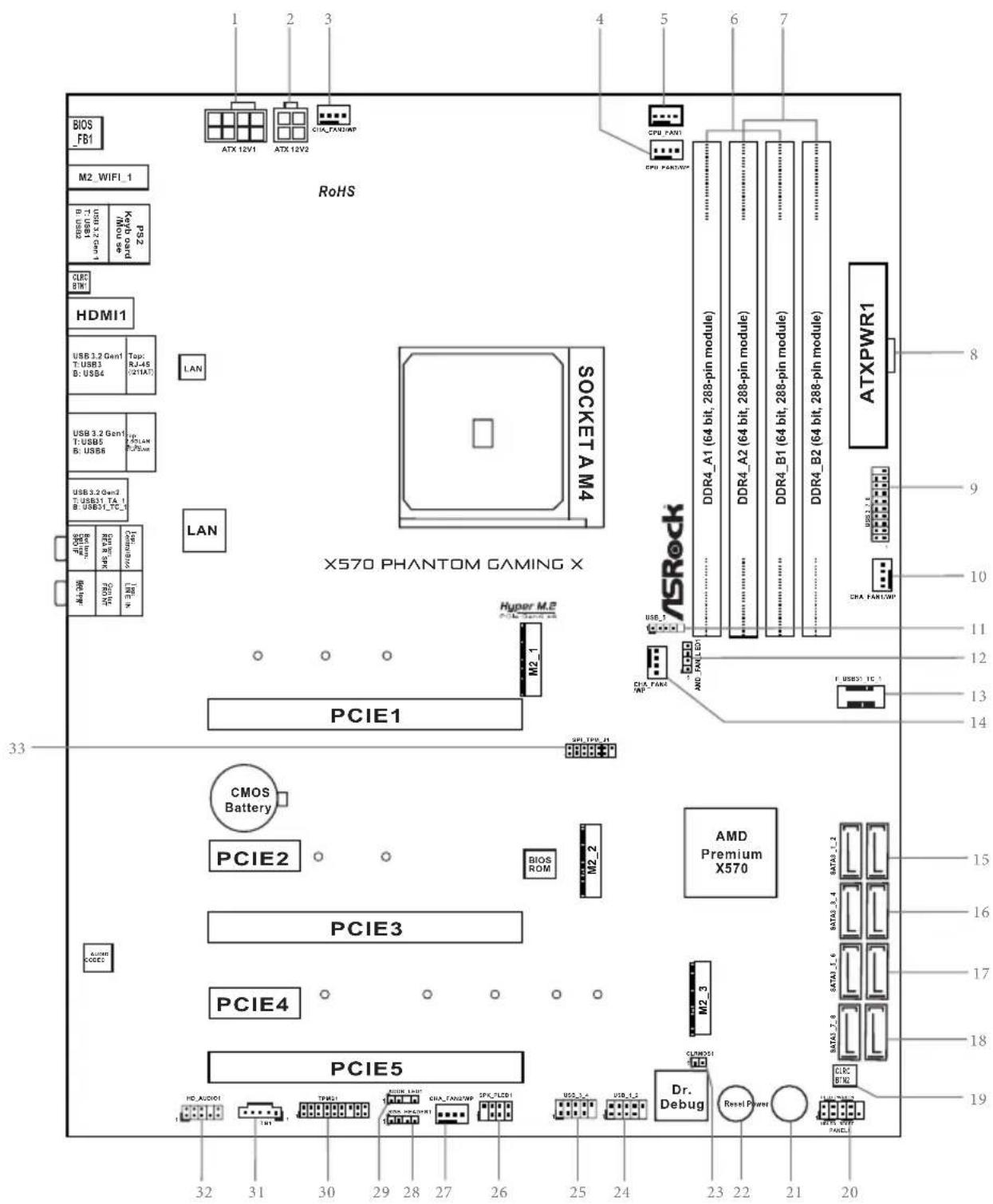
Motherboard Layout
text_image
3.3 32 31 30 29 28 27 26 25 24 23 22 21 20 PCIE4 PCIE3 PCIE2 CMOS Battery PCIE5 BIOS ROM M2_1 M2_2 PCIE1 X570 PHANTOM GAMING X HORSE M2 SOCKET A M4 ROS LAN BIOS USB3.2mA USB3.1mA USB3.0mA USB3.1mA USB3.0mA USB3.1mA USB3.0mA USB3.1mA USB3.0mA USB3.1mA USB3.0mA USB3.1mA USB3.0mA USB3.1mA USB3.0mA USB3.1mA USB3.0mA USB3.1mA USB3.0mA USB2.1mA USB2.0mA USB2.1mA USB2.0mA USB2.1mA USB2.0mA USB2.1mA USB2.0mA USB2.1mA USB2.0mA USB2.1mA USB2.0mA USB2.1mA USB2.0mA USB2.1mA USB2.0mA USB2.1mA USB2.0mANo. Description
18 pin 12V Power Connector (ATX12V1)
2 4 pin 12V Power Connector (ATX12V2)
3 Chassis / Waterpump Fan Connector (CHA_FAN3/WP)
4 CPU / Waterpump Fan Connector (CPU_FAN2/WP)
5 CPU Fan Connector (CPU_FAN1)
6 2 x 288-pin DDR4 DIMM Slots (DDR4_A1, DDR4_B1)
7 2 x 288-pin DDR4 DIMM Slots (DDR4_A2, DDR4_B2)
8 ATX Power Connector (ATXPWR1)
9 USB 3.2 Gen1 Header (USB3_7_8)
10 Chassis / Waterpump Fan Connector (CHA_FAN1/WP)
11 AMD LED Fan USB Header (USB_5)
12 AMD FAN LED Header (AMD_FAN_LED1)
13 Front Panel Type C USB 3.2 Gen2 Header (F_USB31_TC_1)
14 Chassis / Waterpump Fan Connector (CHA_FAN4/WP)
15 SATA3 Connectors (SATA3_1_2)
16 SATA3 Connectors (SATA3_3_4)
17 SATA3 Connectors (SATA3_5_6)
18 SATA3 Connectors (SATA3_7_8)
19 Clear CMOS Button (CLRCBTN2)
20 System Panel Header (PANEL1)
21 Power Button (PWRBTN1)
22 Reset Button (RSTBTN1)
23 Clear CMOS Jumper (CLRCMOS1)
24 USB 2.0 Header (USB_1_2)
25 USB 2.0 Header (USB_3_4)
26 Power LED and Speaker Header (SPK_PLED1)
27 Chassis/Water Pump Fan Connector (CHA_FAN2/WP)
28 RGB LED Header (RGB_HEADER1)
29 Addressable LED Header (ADDR_LED1)
30 TPM Header (TPMS1)
31 Thunderbolt AIC Header (TB1)
32 Front Panel Audio Header (HD_AUDIO1)
33 SPI TPM Header (SPI_TPM_J1)
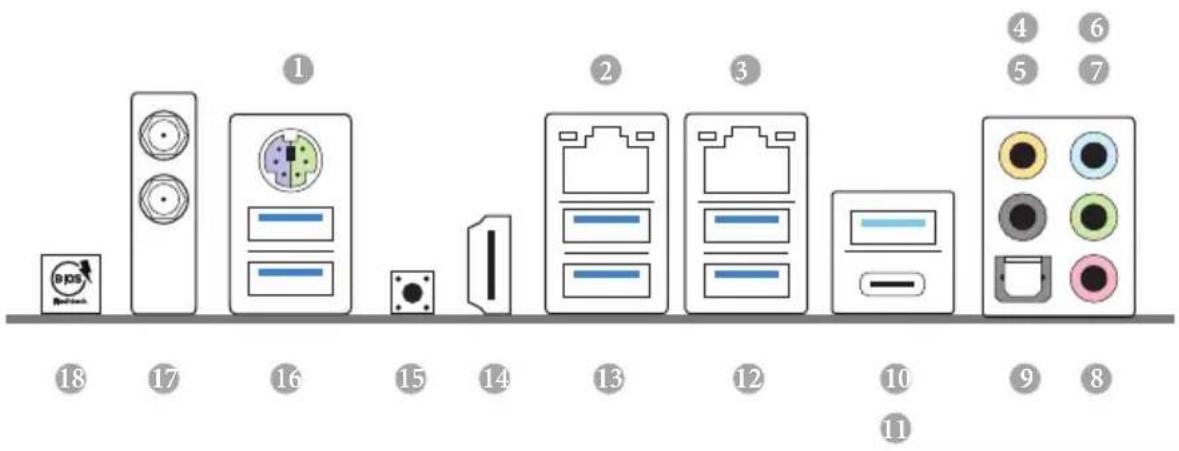
I/O Panel
text_image
① ② ③ ④ ⑤ ⑥ ⑦ ⑧ ⑨ ⑩ ⑪ ⑫ ⑬ ⑭ ⑮ ⑯ ⑰ ⑱ ⑲ ⑳ ㉑ ㉒ ㉓ ㉔ ㉕ ㉖ ㉗ ㉘ ㉙ ㉚ ㉛ ㉜ ㉝ ㉞ ㉟ ㉳ ㉟ ㉟a ㉟b ㉟c ㉟d ㉟e ㉟f ㉟g ㉟h ㉟i ㉟j ㉟k ㉟l ㉟m ㉟n ㉟o ㉟p ㉟q ㉟r ㉟s ㉟t ㉟u ㉟v ㉟w ㉟x ㉟y ㉟zNo. Description No. Description
1 PS/2 Mouse/Keyboard Port (PS2_KB1) 10 USB 3.2 Gen2 Type-A Port (USB31_TA_1)
2 LAN RJ-45 Port (Intel® I211AT)* 11 USB 3.2 Gen2 Type-C Port (USB31_TC_1)
2.5G LAN RJ-45 Port(Dragon RTL8125AG) ^ 12 USB 3.2 Gen1 Ports (USB3_5_6) ^**
4 Central / Bass (Orange) 13 USB 3.2 Gen1 Ports (USB3_3_4)
5 Rear Speaker (Black) 14 HDMI Port
6 Line In (Light Blue) 15 Clear CMOS Button
7 Front Speaker (Lime)*** 16 USB 3.2 Gen1 Ports (USB3_1_2)
8 Microphone (Pink) 17 Antenna Ports
9 Optical SPDIF Out Port 18 BIOS Flashback Button
* There are two LEDs on each LAN port. Please refer to the table below for the LAN port LED indications.
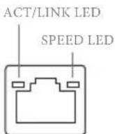
LAN Port
| Activity / Link LED | Speed LED | ||
| Status | Description | Status | Description |
| Off | No Link | Off | 10Mbps connection |
| Blinking | Data Activity | Orange | 100Mbps connection |
| On | Link | Green | 1Gbps connection |
** There are two LEDs on each LAN port. Please refer to the table below for the LAN port LED indications.
ACT/LINK LED
| Activity / Link LED Speed LED | |||
| Status Description Status Description | |||
| Off No Link Off | 10Mbps connection | ||
| Blinking | Data Activity | Orange | 100Mbps/1Gbps connection |
| On Link Green | 2.5Gbps connection | ||
^*** If you use a 2-channel speaker, please connect the speaker's plug into "Front Speaker Jack". See the table below for connection details in accordance with the type of speaker you use.
| Audio Output Channels | Front Speaker (No. 7) | Rear Speaker (No. 5) | Central / Bass (No. 4) | Line In (No.6) |
| 2 V -- -- -- | ||||
| 4 V V -- -- | ||||
| 6 V V V -- | ||||
| 8 V V V V |
**** ACPI wake-up function is not supported on USB3_5_6 ports.
Chapter 1 Introduction
Thank you for purchasing ASRock X570 Phantom Gaming X motherboard, a reliable motherboard produced under ASRock's consistently stringent quality control. It delivers excellent performance with robust design conforming to ASRock's commitment to quality and endurance.

Because the motherboard specifications and the BIOS software might be updated, the content of this documentation will be subject to change without notice. In case any modifications of this documentation occur, the updated version will be available on ASRock's website without further notice. If you require technical support related to this motherboard, please visit our website for specific information about the model you are using. You may find the latest VGA cards and CPU support list on ASRock's website as well. ASRock website http://www.asrock.com.
1.1 Package Contents
• ASRock X570 Phantom Gaming X Motherboard (ATX Form Factor)
• ASRock X570 Phantom Gaming X Quick Installation Guide
• ASRock X570 Phantom Gaming X Support CD
• 4 x Serial ATA (SATA) Data Cables (Optional)
- 1 x ASRock SLI_HB_Bridge_2S Card (Optional)
• 2 x ASRock WiFi 2.4/5 GHz Antennas
• 1 x ASRock Screwdriver (Optional)
• 3 x Screws for M.2 Socket (Optional)
• 2 x Standoffs for M.2 Sockets (Optional)
1.2 Specifications
Platform
- ATX Form Factor
- 2oz Copper PCB
CPU
- Supports AMD AM4 socket Ryzen™ 2000 and 3000 series processors
- Intersil Digital PWM
• 14 Power Phase design
• Supports ASRock Hyper BCLK Engine II
Chipset
- AMD X570
Memory
• Dual Channel DDR4 Memory Technology
- 4 x DDR4 DIMM Slots
- AMD Ryzen series CPUs (Matisse) support DDR4 4666+ (OC)/4400(OC)/4300(OC)/4266(OC)/4200(OC)/4133(OC)/3466(OC)/3200/2933/2667/2400/2133 ECC & non-ECC, unbuffered memory*
- AMD Ryzen series CPUs (Pinnacle Ridge) support DDR4 3600+(OC)/3466(OC)/3200(OC)/2933/2667/2400/2133 ECC & non-ECC, un-buffered memory*
- AMD Ryzen series CPUs (Picasso) support DDR4 3466+ | (OC)/3200(OC)/2933/2667/2400/2133 non-ECC, un-buffered memory*
* For Ryzen Series CPUs (Picasso), ECC is only supported with PRO CPUs.
* Please refer to Memory Support List on ASRock's website for more information. (http://www.asrock.com/)
* Please refer to page 26 for DDR4 UDIMM maximum frequency support.
• Max. capacity of system memory: 128GB
• 15μ Gold Contact in DIMM Slots
Expansion
AMD Ryzen series CPUs (Matisse)
Slot
- 3 x PCI Express 4.0 x16 Slots (PCIE1/PCIE3/PCIE5: single at x16 (PCIE1); dual at x8 (PCIE1) / x8 (PCIE3); triple at x8 (PCIE1) / x8 (PCIE3) / x4 (PCIE5))*
AMD Ryzen series CPUs (Pinnacle Ridge)
- 3 x PCI Express x16 Slots (PCIE1/PCIE3/PCIE5: single at Gen3x16 (PCIE1); dual at Gen3x8 (PCIE1) / Gen3x8 (PCIE3); triple at Gen3x8 (PCIE1) / Gen3x8 (PCIE3) / Gen4x4 (PCIE5))*
AMD Ryzen series CPUs (Picasso)
• 1 x PCI Express 3.0 x16 Slot (single at x8 (PCIE1))*
• 1 x PCI Express 4.0 x16 Slot (single at x4 (PCIE5))*
* Supports NVMe SSD as boot disks
• 2 x PCI Express 4.0 x1 Slots
- Supports AMD Quad CrossFireX ^TM , 3-Way CrossFireX ^TM and CrossFireX ^TM
• Supports NVIDIA® Quad SLI ^TM and SLI ^TM^**
- Supports NVIDIA® NVLink ^TM with dual NVIDIA® GeForce® RTX series graphics cards**
** NVIDIA NVLink Bridge does not come with the package. Please purchase it from NVIDIA ^ if necessary.
** This feature is only supported with Ryzen Series CPUs (Pinnacle Ridge).
- 1 x Vertical M.2 Socket (Key E) with the bundled WiFi-802.11ax module (on the rear I/O)
• 15μ Gold Contact in VGA PCIe Slot (PCIE1)
Graphics
- Integrated AMD Radeon ^TM Vega Series Graphics in Ryzen Series APU*
* Actual support may vary by CPU
- DirectX 12, Pixel Shader 5.0
- Shared memory default 2GB. Max Shared memory supports up to 16GB.
* The Max shared memory 16GB requires 32GB system memory installed.
- Supports HDMI 2.0 with max. resolution up to 4K x 2K (4096x2160) @ 60Hz
- Supports Auto Lip Sync, Deep Color (12bpc), xvYCC and HBR (High Bit Rate Audio) with HDMI 2.0 Ports (Compliant HDMI monitor is required)
• Supports HDR (High Dynamic Range) with HDMI 2.0
• Supports HDCP 2.2 with HDMI 2.0 Port
• Supports 4K Ultra HD (UHD) playback with HDMI 2.0 Port
• Supports Microsoft PlayReady®
Audio
- 7.1 CH HD Audio with Content Protection (Realtek ALC1220 Audio Codec)
• Premium Blu-ray Audio support
• Supports Surge Protection - NE5532 Premium Headset Amplifier for Front Panel Audio Connector (Supports up to 600 Ohm headsets)
- Pure Power-In
- Direct Drive Technology
• PCB Isolate Shielding
• Impedance Sensing on Rear Out port
• Individual PCB Layers for R/L Audio Channel
• Gold Audio Jacks
• 15μ Gold Audio Connector
• Supports Creative SoundBlaster Cinema5
LAN
1 x 2.5 Gigabit LAN 10/100/1000/2500 Mb/s (Dragon RTL8125AG):
• Supports Phantom Gaming LAN Software
- Smart Auto Adjust Bandwidth Control
- Visual User Friendly UI
- Visual Network Usage Statistics
- Optimized Default Setting for Game, Browser, and Streaming Modes
- User Customized Priority Control
• Supports Wake-On-LAN
• Supports Lightning/ESD Protection
• Supports Energy Efficient Ethernet 802.3az
• Supports PXE
1 x Intel Gigabit LAN 10/100/1000 Mb/s (1 x Intel® I211AT):
• Supports Wake-On-LAN
• Supports Lightning/ESD Protection
• Supports Energy Efficient Ethernet 802.3az
- Supports PXE
Wireless
LAN
-
Intel® 802.11ax WiFi Module
• Supports IEEE 802.11a/b/g/n/ax
• Supports Dual-Band (2.4/5 GHz)
• Supports WiFi6 802.11ax (2.4Gbps) -
2 antennas to support 2 (Transmit) x 2 (Receive) diversity technology
• Supports Bluetooth 5.0 + High speed class II
• Supports MU-MIMO
Rear Panel I/O
- 2 x Antenna Ports
• 1 x PS/2 Mouse/Keyboard Port - 1 x HDMI Port
• 1 x Optical SPDIF Out Port - 1 x USB 3.2 Gen2 Type-A Port (10 Gb/s) (Supports ESD Protection)
- 1 x USB 3.2 Gen2 Type-C Port (10 Gb/s) (Supports ESD Protection)
- 6 x USB 3.2 Gen1 Ports (Supports ESD Protection)
* Ultra USB Power is supported on USB3_5_6 ports.
* ACPI wake-up function is not supported on USB3_5_6ports.
- 2 x RJ-45 LAN Ports with LED (ACT/LINK LED and SPEED LED)
• 1 x Clear CMOS Button
• 1 x BIOS Flashback Button - HD Audio Jacks: Rear Speaker / Central / Bass / Line in / Front Speaker / Microphone (Gold Audio Jacks)
Storage
- 8 x SATA3 6.0 Gb/s Connectors, support RAID (RAID 0, RAID 1 and RAID 10), NCQ, AHCI and Hot Plug
- 1 x Hyper M.2 Socket (M2_1), supports M Key type 2242/2260/2280 M.2 SATA3 6.0 Gb/s module and M.2 PCI Express module up to Gen4x4 (64 Gb/s) (with Matisse) or Gen3x4 (32 Gb/s) (with Pinnacle Ridge and Picasso)*
- 1 x Hyper M.2 Socket (M2_2), supports M Key type 2260/2280 M.2 PCI Express module up to Gen4x4 (64 Gb/s)*
- 1 x Hyper M.2 Socket (M2_3), supports M Key type 2230/2242/2260/2280/22110 M.2 SATA3 6.0 Gb/s module and M.2 PCI Express module up to Gen4x4 (64 Gb/s)*
* If M2_3 is occupied, PCIE5 slot will be disabled
* Supports NVMe SSD as boot disks
* Supports ASRock U.2 Kit
Connector
- 1 x TPM Header
• 1 x SPI TPM Header
• 1 x Power LED and Speaker Header
• 1 x AMD Fan LED Header
* The AMD Fan LED Header is compatible with a regular RGB LED stripe.
* The AMD Fan LED Header supports LED strips of maximum load of 3A (36W) and length up to 2.5M.
• 1 x RGB LED Header
* Supports in total up to 12V/3A, 36W LED Strip
• 1 x Addressable LED Header
* Supports in total up to 5V/3A, 15W LED Strip
• 1 x CPU Fan Connector (4-pin)
* The CPU Fan Connector supports the CPU fan of maximum 1A (12W) fan power.
- 1 x CPU/Water Pump Fan Connector (4-pin) (Smart Fan Speed Control)
* The CPU/Water Pump Fan supports the water cooler fan of maximum 2A (24W) fan power.
4 x Chassis/Water Pump Fan Connectors (4-pin) (Smart Fan Speed Control)
* The Chassis/Water Pump Fan supports the water cooler fan of maximum 2A (24W) fan power.
* CPU_FAN2/WP, CHA_FAN1/WP, CHA_FAN2/WP, CHA_FAN3/WP and CHA_FAN4/WP can auto detect if 3-pin or 4-pin fan is in use.
- 1 x 24 pin ATX Power Connector (Hi-Density Power Connector)
- 1 x 8 pin 12V Power Connector (Hi-Density Power Connector)
- 1 x 4 pin 12V Power Connector (Hi-Density Power Connector)
- 1 x Front Panel Audio Connector (15μ Gold Audio Connector)
• 1 x AMD LED Fan USB Header - 1 x Thunderbolt AIC Connector (5-pin) (Supports ASRock Thunderbolt AIC Card only)
- 2 x USB 2.0 Headers (Support 4 USB 2.0 ports) (Supports ESD Protection)
- 1 x USB 3.2 Gen1 Header (Supports 2 USB 3.2 Gen1 ports) (Supports ESD Protection)
- 1 x Front Panel Type C USB 3.2 Gen2 Header (Supports ESD Protection)
• 1 x Dr. Debug with LED
• 1 x Power Button with LED
• 1 x Reset Button with LED
• 1 x Clear CMOS Button
BIOS Feature
• AMI UEFI Legal BIOS with GUI support
• Supports "Plug and Play"
• ACPI 5.1 compliance wake up events
• Supports jumperfree
- SMBIOS 2.3 support
- CPU, CPU VDDCR_SOC, DRAM, VPPM, PREM VDD_CLDO, PERM VDDCR_SOC, +1.8V, VDDP Voltage Multi-adjustment
Hardware Monitor
- Temperature Sensing: CPU, CPU/Water Pump, Chassis, Chassis/Water Pump Fans
- Fan Tachometer: CPU, CPU/Water Pump, Chassis, Chassis/Water Pump Fans
- Quiet Fan (Auto adjust chassis fan speed by CPU temperature): CPU, CPU/Water Pump, Chassis, Chassis/Water Pump Fans
- Fan Multi-Speed Control: CPU, CPU/Water Pump, Chassis, Chassis/Water Pump Fans
- Voltage monitoring: +12V, +5V, +3.3V, CPU Vcore, CPU VDDCR_SOC, DRAM, VPPM, PREM VDDCR_SOC, +1.8V, VDDP
OS
- Microsoft® Windows® 10 64-bit
Certifica- tions
- FCC, CE
- ErP/EuP ready (ErP/EuP ready power supply is required)
* For detailed product information, please visit our website: http://www.asrock.com

Please realize that there is a certain risk involved with overclocking, including adjusting the setting in the BIOS, applying Untied Overclocking Technology, or using third-party overclocking tools. Overclocking may affect your system's stability, or even cause damage to the components and devices of your system. It should be done at your own risk and expense. We are not responsible for possible damage caused by overclocking.
1.3 WiFi-802.11ax Module and ASRock WiFi 2.4/5 GHz Antenna
WiFi-802.11ax + BT Module
This motherboard comes with an exclusive WiFi 802.11 a/b/g/n/ax + BT v5.0 module (pre-installed on the rear I/O panel) that offers support for WiFi 802.11 a/b/g/n/ax connectivity standards and Bluetooth v5.0. WiFi + BT module is an easy-to-use wireless local area network (WLAN) adapter to support WiFi + BT. Bluetooth v5.0 standard features Smart Ready technology that adds a whole new class of functionality into the mobile devices. BT 5.0 also includes Low Energy Technology and ensures extraordinary low power consumption for PCs. The 2T2R WiFi solution sets a WiFi high speed standard and offers max link rate up to 2.4Gbps.
* The transmission speed may vary according to the environment.
Chapter 2 Installation
This is an ATX form factor motherboard. Before you install the motherboard, study the configuration of your chassis to ensure that the motherboard fits into it.
Pre-installation Precautions
Take note of the following precautions before you install motherboard components or change any motherboard settings.
- Make sure to unplug the power cord before installing or removing the motherboard. Failure to do so may cause physical injuries to you and damages to motherboard components.
- In order to avoid damage from static electricity to the motherboard's components, NEVER place your motherboard directly on a carpet. Also remember to use a grounded wrist strap or touch a safety grounded object before you handle the components.
- Hold components by the edges and do not touch the ICs.
- Whenever you uninstall any components, place them on a grounded anti-static pad or in the bag that comes with the components.
- When placing screws to secure the motherboard to the chassis, please do not over-tighten the screws! Doing so may damage the motherboard.
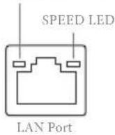
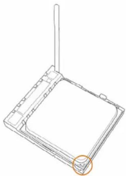
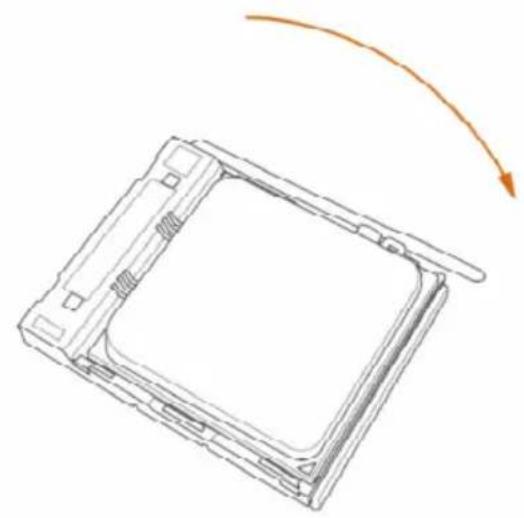
2.1 Installing the CPU

Unplug all power cables before installing the CPU.
1
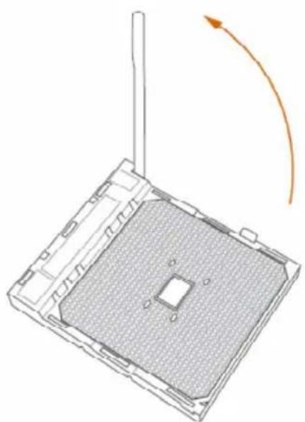
natural_image
Diagram of a square electronic device with a central grid and antenna, showing an orange curved arrow indicating rotation or movement (no text or symbols present)2
natural_image
Technical line drawing of a square mechanical component with a vertical rod and circular highlight (no text or symbols)3
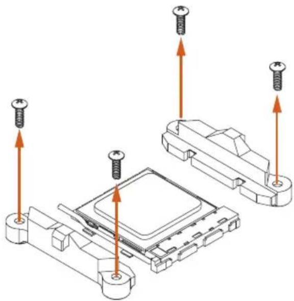
natural_image
Technical line drawing of a rectangular electronic component with a curved arrow indicating rotation (no text or symbols)2.2 Installing the CPU Fan and Heatsink
After you install the CPU into this motherboard, it is necessary to install a larger heatsink and cooling fan to dissipate heat. You also need to spray thermal grease between the CPU and the heatsink to improve heat dissipation. Make sure that the CPU and the heatsink are securely fastened and in good contact with each other.

Please turn off the power or remove the power cord before changing a CPU or heatsink.
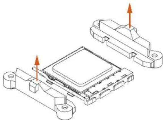
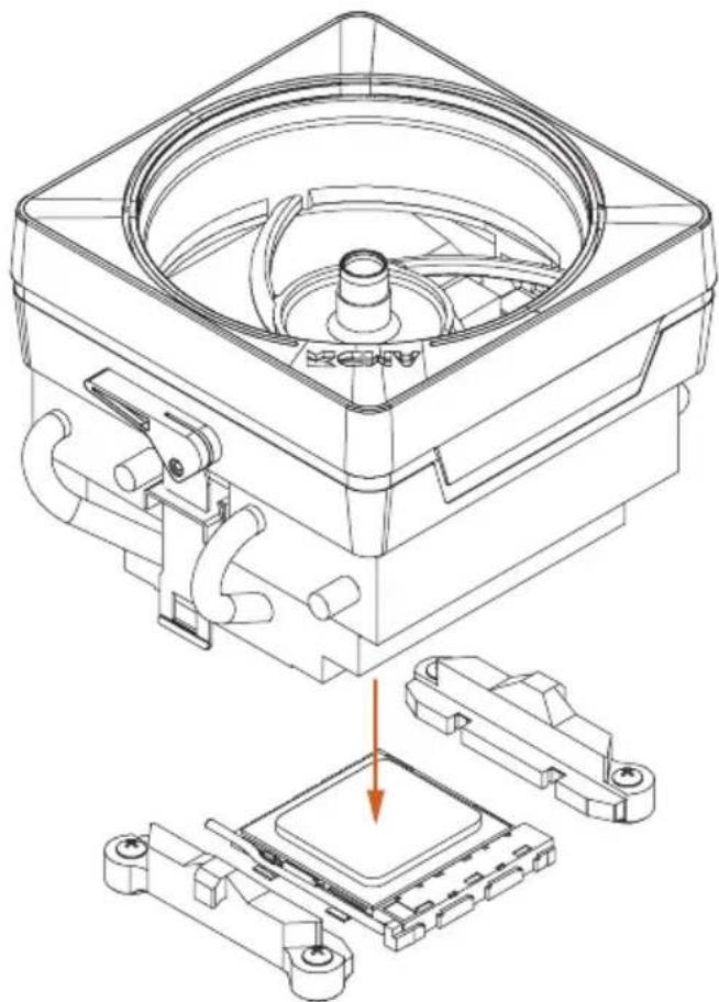
Installing the CPU Box Cooler SR1
1
natural_image
Technical diagram showing screw fasteners inserted into a microchip assembly (no text or labels)2
natural_image
Technical line drawing of an electronic component with two housing parts and orange arrows indicating assembly or movement (no text or symbols)3
text_image
Technical diagram showing assembly of a device with labeled components and directional arrows indicating assembly steps.4
natural_image
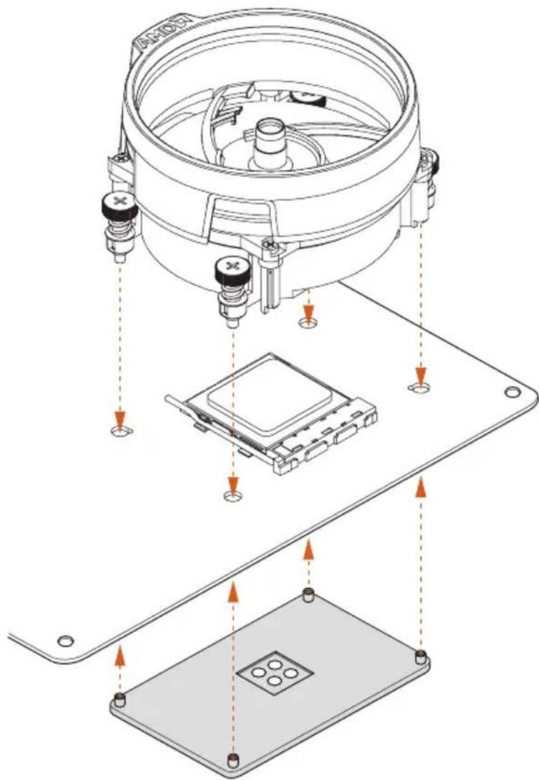
Technical line drawing of a mechanical device with mounting base and wiring, no visible text or symbolsInstalling the AM4 Box Cooler SR2
1
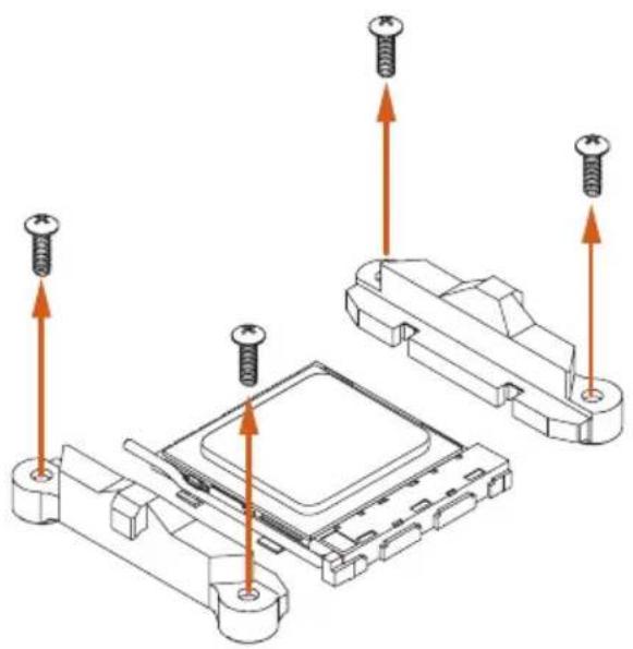
natural_image
Technical diagram showing screw installation components with arrows indicating assembly (no text or labels)2
natural_image
Technical line drawing of a mechanical component with mounting holes and internal structure (no text or symbols)3
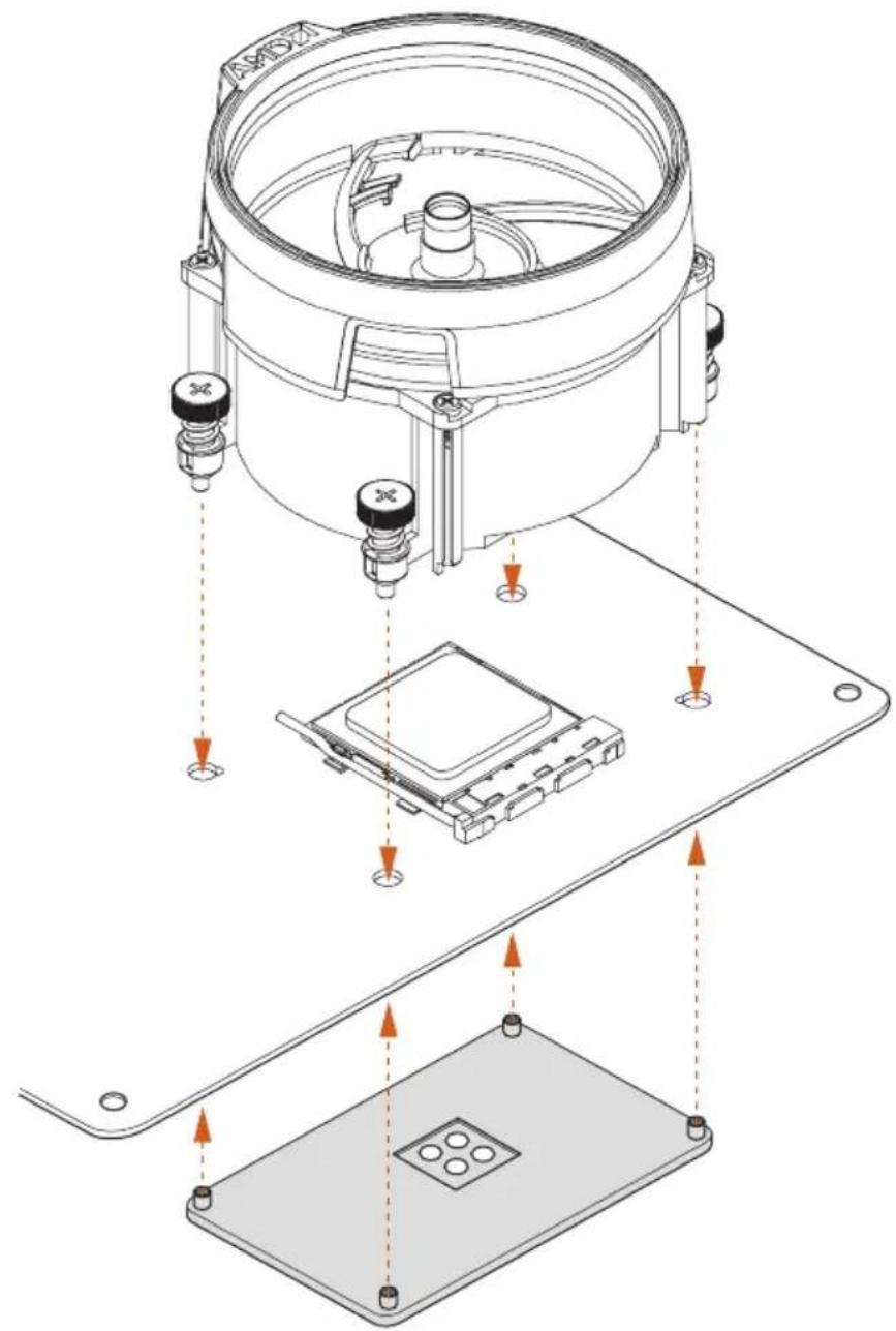
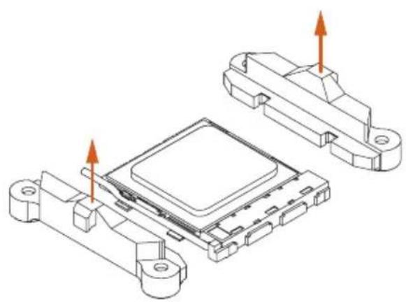
natural_image
Technical diagram of a mechanical assembly with exploded view and mounting base (no text or symbols)4
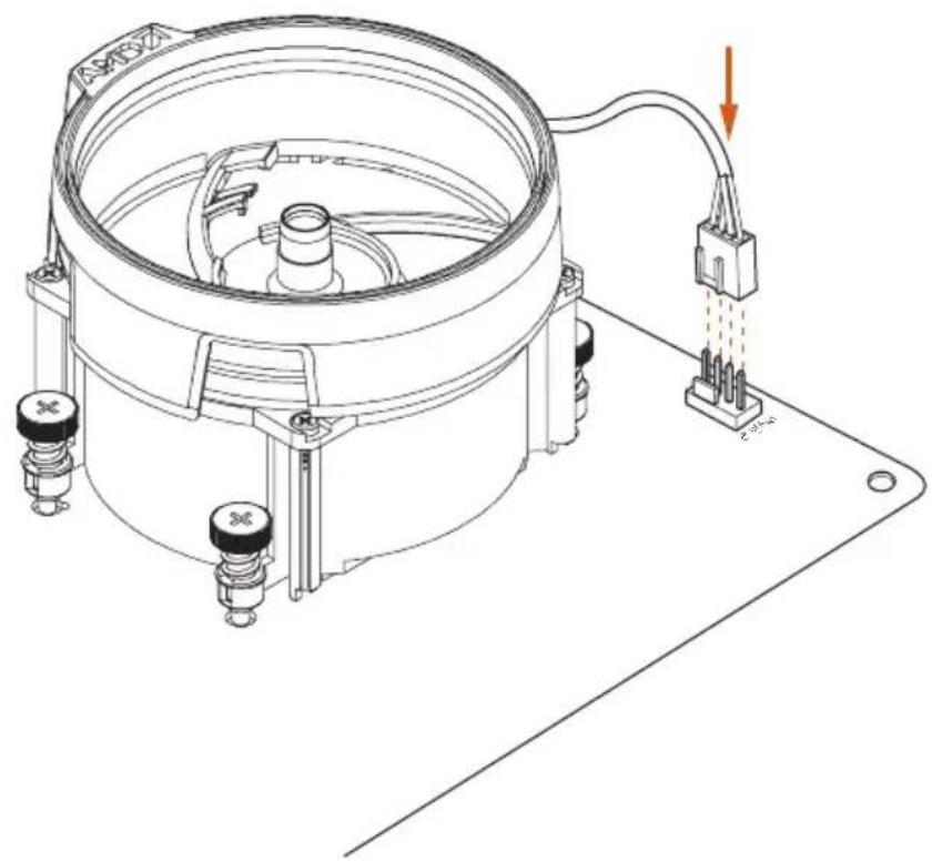
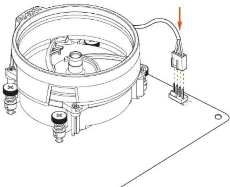
natural_image
Technical line drawing of a mechanical device with mounting base and wiring, no visible text or symbols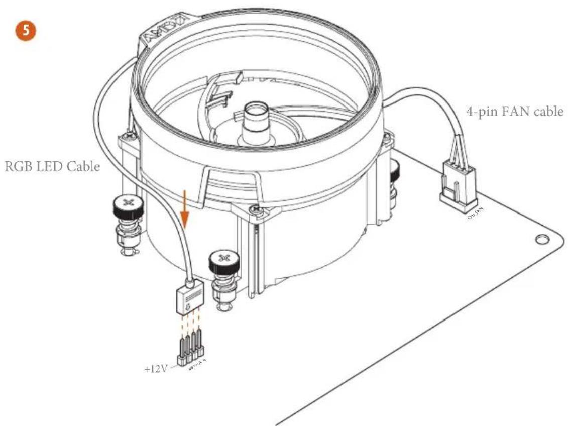
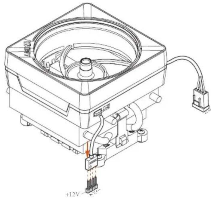
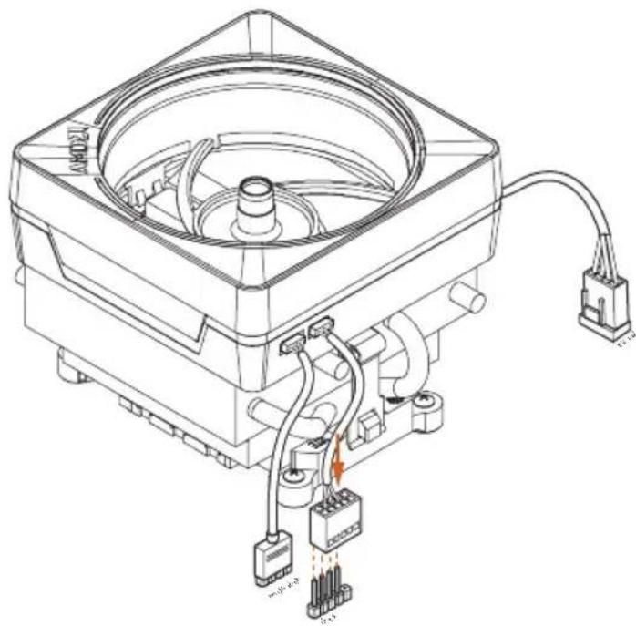
text_image
5 RGB LED Cable +12V 4-pin FAN cable*The diagrams shown here are for reference only. The headers might be in a different position on your motherboard. Please refer to page 36 for the orientation of AMD Fan LED Header (AMD_FAN_LED1).
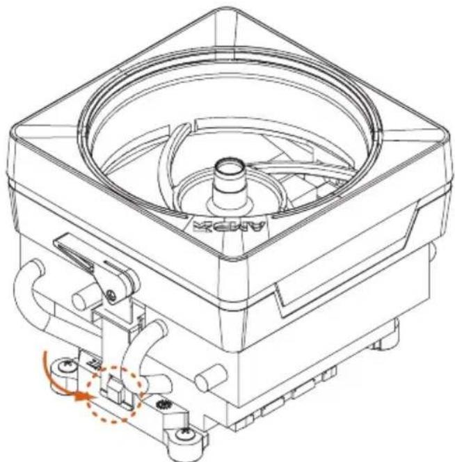
Installing the AM4 Box Cooler SR3
1
natural_image
Technical line drawing of a mechanical assembly with a central component and base, showing internal components and a downward arrow indicating motion (no text or symbols present)2
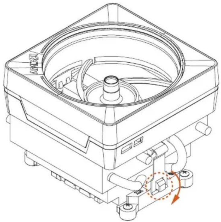
natural_image
Technical line drawing of a mechanical device with no visible text or symbols3
natural_image
Technical line drawing of a mechanical device with no visible text or symbols4
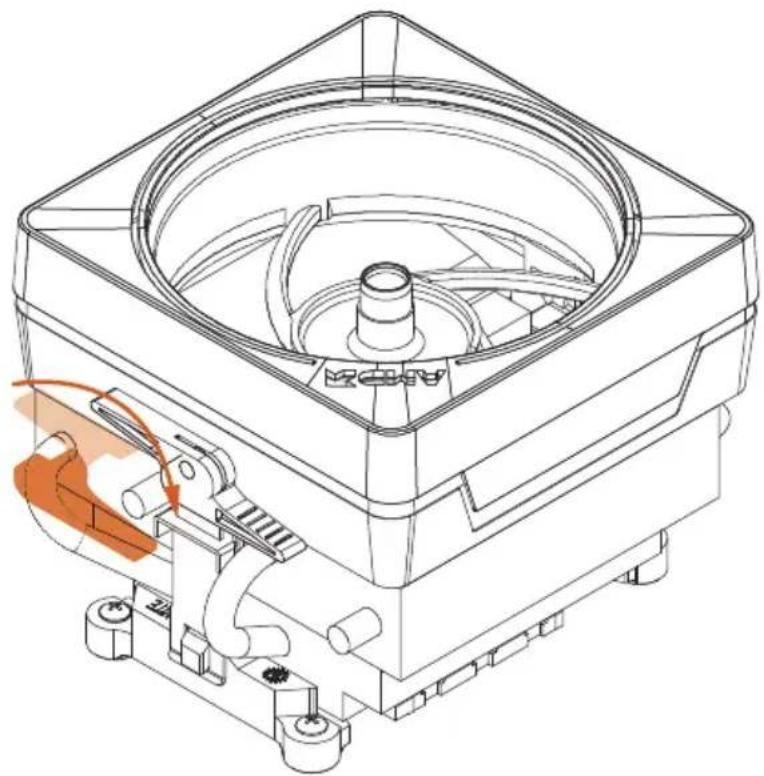
natural_image
Technical line drawing of a mechanical device with internal components and a highlighted orange section (no text or symbols)5
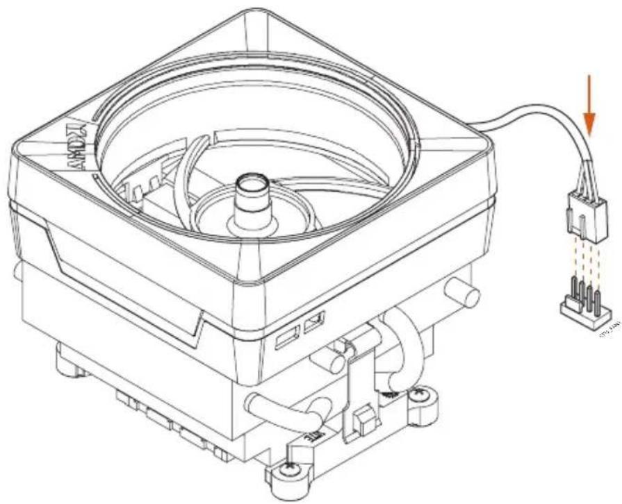
natural_image
Technical line drawing of a mechanical device with a central fan and attached wiring (no text or symbols)6
text_image
+12V +5.0V
7
natural_image
Technical line drawing of a mechanical device with internal components and wiring (no text or symbols)Please note that only one cable should be used at a time in this step.
If you select AMD_FAN_LED1, please install ASRock utility "ASRock Polychrome SYNC".
If you select USB connector, please install AMD utility "SR3 Settings Software".
*The diagrams shown here are for reference only. The headers might be in a different position on your motherboard. Please refer to page 36 for the orientation of AMD Fan LED Header (AMD_FAN_LED1) and page 32 for the orientation of AMD LED Fan USB Header (USB_5).
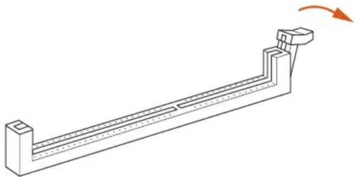
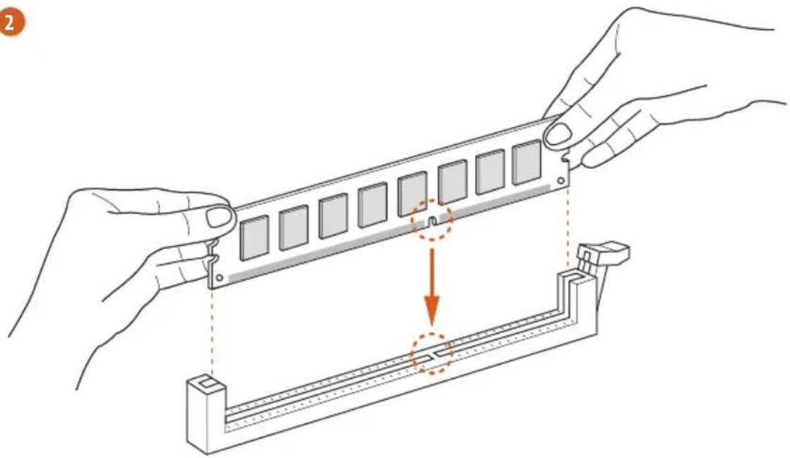
2.3 Installing Memory Modules (DIMM)
This motherboard provides four 288-pin DDR4 (Double Data Rate 4) DIMM slots, and supports Dual Channel Memory Technology.

- For dual channel configuration, you always need to install identical (the same brand, speed, size and chip-type) DDR4 DIMM pairs.
- It is unable to activate Dual Channel Memory Technology with only one or three memory module installed.
- It is not allowed to install a DDR, DDR2 or DDR3 memory module into a DDR4 slot; otherwise, this motherboard and DIMM may be damaged.
- We suggest that you install the memory modules on DDR4_A2 and DDR4_B2 first for better DRAM compatibility on 2 DIMMs configuration.
AMD non-XMP Memory Frequency Support
Ryzen Series CPUs (Matisse):
UDIMM Memory Slot
A1 A2 B1 B2
Frequency
(Mhz)
- SR -- 3200
- DR -- 3200
- SR - SR 3200
- DR - DR 3200
SR SR SR SR 2933
SR/DR DR SR/DR DR 2667
SR/DR SR/DR SR/DR SR/DR 2667
Ryzen Series CPUs (Pinnacle Ridge):
UDIMM Memory Slot
A1 A2 B1 B2
Frequency
(Mhz)
- SR -- 2933
- DR -- 2933
- SR - SR 2933
- DR - DR 2933
SR SR SR SR 2933
SR/DR DR SR/DR DR 2667
SR/DR SR/DR SR/DR SR/DR 2133-2400
Ryzen Series CPUs (Picasso):
| UDIMM Memory SlotA1 A2 B1 B2 | Frequency(Mhz) |
- SR - - 2933
-DR--2667 - SR - SR 2667
- DR - DR 2400
SR SR SR SR 2133
SR/DR DR SR/DR DR 1866
SR/DR SR/DR SR/DR SR/DR 1866
SR: Single rank DIMM, 1Rx4 or 1Rx8 on DIMM module label
DR: Dual rank DIMM, 2Rx4 or 2Rx8 on DIMM module label

The DIMM only fits in one correct orientation. It will cause permanent damage to the motherboard and the DIMM if you force the DIMM into the slot at incorrect orientation.
1
natural_image
Technical line drawing of a mechanical lever or support structure with a rotation arrow indicating motion (no text or symbols present)2
natural_image
Illustration of hands assembling a mechanical component with a highlighted section (no text or symbols)3
natural_image
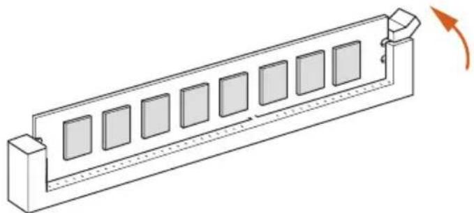
Isometric line drawing of a rectangular electronic component with multiple square slots and a curved arrow indicating rotation (no text or symbols)2.4 Expansion Slots (PCI Express Slots)
There are 5 PCI Express slots on the motherboard.

Before installing an expansion card, please make sure that the power supply is switched off or the power cord is unplugged. Please read the documentation of the expansion card and make necessary hardware settings for the card before you start the installation.
PCIe slots:
PCIE1 (PCIe 4.0 x16 slot) is used for PCI Express x16 lane width graphics cards.
PCIE2 (PCIe 4.0 x1 slot) is used for PCI Express x1 lane width cards.
PCIE3 (PCIe 4.0 x16 slot) is used for PCI Express x8 lane width graphics cards.
PCIE4 (PCIe 4.0 x1 slot) is used for PCI Express x1 lane width cards.
PCIE5 (PCIe 4.0 x16 slot) is used for PCI Express x4 lane width graphics cards.
* If PCIE5 slot is occupied, M2_3 will be disabled.
PCIe Slot Configurations
PCIE1 PCIE3 PCIE5
Ryzen Series CPUs (Matisse) Gen4x8 Gen4x8 Gen4x4
Ryzen Series CPUs (Pinnacle Ridge) Gen3x8 Gen3x8 Gen4x4
| Gen3x8 | N/A | N/A | |
| Ryzen Series CPUs (Picasso) | N/A | N/A | Gen4x4 |

For a better thermal environment, please connect a chassis fan to the motherboard's chassis fan connector (CHA_FAN1/WP, CHA_FAN2/WP, CHA_FAN3/WP or CHA_FAN4/WP) when using multiple graphics cards.
2.5 Jumpers Setup
The illustration shows how jumpers are setup. When the jumper cap is placed on the pins, the jumper is “Short”. If no jumper cap is placed on the pins, the jumper is “Open”.
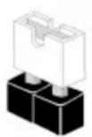
Short
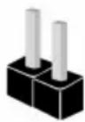
Open
Clear CMOS Jumper
(CLRCMOS1)
(see p.1, No. 23)

2-pin Jumper
Short: Clear CMOS
Open: Default
CLRCMOS1 allows you to clear the data in CMOS. The data in CMOS includes system setup information such as system password, date, time, and system setup parameters. To clear and reset the system parameters to default setup, please turn off the computer and unplug the power cord, then use a jumper cap to short the pins on CLRCMOS1 for 3 seconds. Please remember to remove the jumper cap after clearing the CMOS. If you need to clear the CMOS when you just finish updating the BIOS, you must boot up the system first, and then shut it down before you do the clear-CMOS action.

The Clear CMOS Button has the same function as the Clear CMOS jumper.
2.6 Onboard Headers and Connectors

Onboard headers and connectors are NOT jumpers. Do NOT place jumper caps over these headers and connectors. Placing jumper caps over the headers and connectors will cause permanent damage to the motherboard.
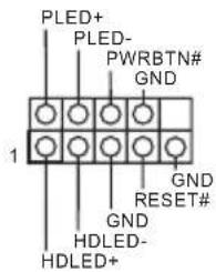
System Panel Header (9-pin PANEL1) (see p.1, No. 20)
text_image
PLED+ PLED- PWRBTN# GND 1 GND RESET# GND HDLED- HDLED+Connect the power button, reset button and system status indicator on the chassis to this header according to the pin assignments below. Note the positive and negative pins before connecting the cables.

PWRBTN (Power Button):
Connect to the power button on the chassis front panel. You may configure the way to turn off your system using the power button.
RESET (Reset Button):
Connect to the reset button on the chassis front panel. Press the reset button to restart the computer if the computer freezes and fails to perform a normal restart.
PLED (System Power LED):
Connect to the power status indicator on the chassis front panel. The LED is on when the system is operating. The LED keeps blinking when the system is in S1/S3 sleep state. The LED is off when the system is in S4 sleep state or powered off (S5).
HDLED (Hard Drive Activity LED):
Connect to the hard drive activity LED on the chassis front panel. The LED is on when the hard drive is reading or writing data.
The front panel design may differ by chassis. A front panel module mainly consists of power button, reset button, power LED, hard drive activity LED, speaker and etc. When connecting your chassis front panel module to this header, make sure the wire assignments and the pin assignments are matched correctly.
Power LED and Speaker Header
(7-pin SPK_PLED1)
(see p.1, No. 26)
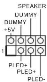
Please connect the chassis power LED and the chassis speaker to this header.
Serial ATA3 Connectors
(SATA3_1_2:
see p.1, No. 15)
(SATA3_3_4:
see p.1, No. 16)
(SATA3_5_6:
see p.1, No. 17)
(SATA3_7_8:
see p.1, No. 18)
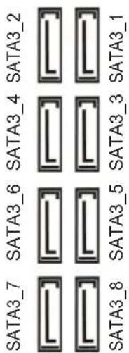
text_image
SATA3_7 SATA3_6 SATA3_4 SATA3_2 SATA3_8 SATA3_5 SATA3_3 SATA3_1These eight SATA3 connectors support SATA data cables for internal storage devices with up to 6.0 Gb/s data transfer rate.
AMD LED Fan USB
Header
(4-pin USB_5)
(see p.1, No. 11)
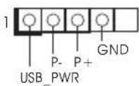
This header is used for connecting the USB connector on the AMD SR3 Heatsink.
USB 2.0 Headers
(9-pin USB_1_2)
(see p.1, No. 24)
(9-pin USB_3_4)
(see p.1, No. 25)
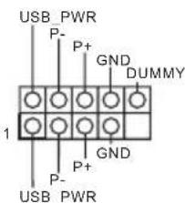
text_image
USB PWR P- P+ GND DUMMY 1 P- GND P+ USB PWRThere are two headers on this motherboard. Each USB 2.0 header can support two ports.
USB 3.2 Gen1 Header
(19-pin USB3_7_8)
(see p.1, No. 9)
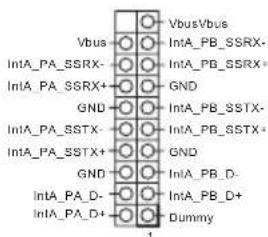
text_image
Vbus IntA_PA_SSRX- IntA_PA_SSRX+ GND IntA_PA_SSTX- IntA_PA_SSTX+ GND IntA_PA_D- IntA_PA_D+ Vbus/Vbus IntA_PB_SSRX- GND IntA_PB_SSTX- IntA_PB_SSTX+ GND IntA_PB_D- IntA_PB_D+ Dummy 1There is a header on this motherboard. This USB 3.2 Gen1 header can support two ports.
Front Panel Type C USB 3.2 Gen2 Header (20-pin F_USB31_TC_1) (see p.1, No. 13)
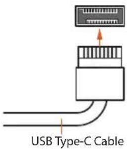
text_image
USB Type-C CableThere is one Front Panel Type C USB 3.2 Gen2 Header on this motherboard. This header is used for connecting a USB 3.2 Gen2 module for additional USB 3.2 Gen2 ports.
Front Panel Audio Header (9-pin HD_AUDIO1) (see p.1, No. 32)
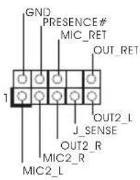
text_image
GND PRESENCE# MIC_RET OUT_RET 1 J_SENSE OUT2_L MIC2_R MIC2_LThis header is for connecting audio devices to the front audio panel.

- High Definition Audio supports Jack Sensing, but the panel wire on the chassis must support HDA to function correctly. Please follow the instructions in our manual and chassis manual to install your system.
- If you use an AC'97 audio panel, please install it to the front panel audio header by the steps below:
A. Connect Mic_IN (MIC) to MIC2_L.
B. Connect Audio_R (RIN) to OUT2_R and Audio_L (LIN) to OUT2_L.
C. Connect Ground (GND) to Ground (GND).
D. MIC_RET and OUT_RET are for the HD audio panel only. You don't need to connect them for the AC'97 audio panel.
E. To activate the front mic, go to the "FrontMic" Tab in the Realtek Control panel and adjust "Recording Volume".
Chassis Water Pump Fan Connectors
(4-pin CHA_FAN1/WP) (see p.1, No. 10)
(4-pin CHA_FAN2/WP) (see p.1, No. 27)
(4-pin CHA_FAN3/WP) (see p.1, No. 3)
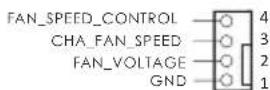
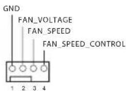
text_image
GND FAN_VOLTAGE FAN_SPEED FAN_SPEED_CONTROL 1 2 3 4This motherboard provides four 4-Pin water cooling chassis fan connectors. If you plan to connect a 3-Pin chassis water cooler fan, please connect it to Pin 1-3.
(4-pin CHA_FAN4/WP)
(see p.1, No. 14)
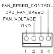
CPU Fan Connector
(4-pin CPU_FAN1)
(see p.1, No. 5)
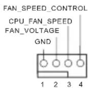
This motherboard pro-
(Quiet Fan) connector.
If you plan to connect a
3-Pin CPU fan, please
connect it to Pin 1-3.
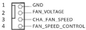
CPU Water Pump Fan
Connector
(4-pin CPU_FAN2/WP)
(see p.1, No. 4)
This motherboard
provides a 4-Pin water
cooling CPU fan
connector. If you plan
to connect a 3-Pin CPU
water cooler fan, please
connect it to Pin 1-3.
ATX Power Connector
(24-pin ATXPWR1)
(see p.1, No. 8)
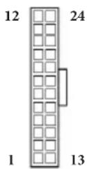
This motherboard pro-
vides a 24-pin ATX power
connector. To use a 20-pin
ATX power supply, please
plug it along Pin 1 and Pin
13.
ATX 12V Power
Connector
(8-pin ATX12V1)
(see p.1, No. 1)
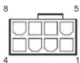
This motherboard pro-
vides an 8-pin ATX 12V
power connector. To use a
4-pin ATX power supply,
please plug it along Pin 1
and Pin 5.
*Warning: Please make
sure that the power cable
connected is for the CPU
and not the graphics
card. Do not plug the
PCIe power cable to this
connector.
ATX 12V Power
Connector
(4-pin ATX12V2)
(see p.1, No. 2)
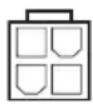
Please connect an ATX
12V power supply to this connector.
*The power supply plug fits into this connector in only one orientation.
LPC/TPM Header
(17-pin TPMS1)
(see p.1, No. 30)
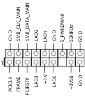
text_image
GND SMB_CLK_MAIN SMB_DATA_MAIN LAD2 LAD1 GND S_PWRDOWN# SERIRQ# GND PCCLK FRAME PCIRST# LAD3 +3 V LAD0 +3VSB GNDThis connector supports Trusted Platform Module (TPM) system, which can securely store keys, digital certificates, passwords, and data. A TPM system also helps enhance network security, protects digital identities, and ensures platform integrity.
SPI TPM Header
(13-pin SPI_TPM_J1)
(see p.1, No. 33)
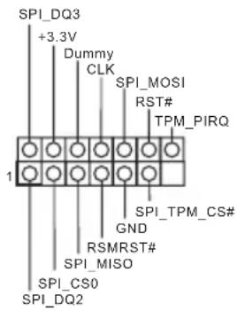
text_image
SPI_DQ3 +3.3V Dummy CLK SPI_MOSI RST# TPM_PIRQ 1 SPI_TPM_CS# GND RSMRST# SPI_MISO SPI_CS0 SPI_DQ2This connector supports SPI
Trusted Platform Module (TPM) system, which can securely store keys, digital certificates, passwords, and data. A TPM system also helps enhance network security, protects digital identities, and ensures platform integrity.
Thunderbolt AIC
Connector
(5-pin TB1)
(see p.1, No. 31)
Please connect a Thunderbolt™ add-in card (AIC) to the Thunderbolt AIC connector via the GPIO cable.
*Please install the Thunderbolt™ AIC card to PCIE5 (default slot).
*For the further information, please visit www.asrock.com.
AMD FAN LED Header (4-pin AMD_FAN_ LED1) (see p.1, No. 12)
AMD FAN LED Header is used to connect RGB LED extension cable that comes with AMD heatsink. The cable connection allows users to choose from various LED lighting effects.
*The AMD Fan LED Header is compatible with a regular RGB LED stripe.
Caution: Never install the FAN LED cable in the wrong orientation; otherwise, the cable may be damaged.
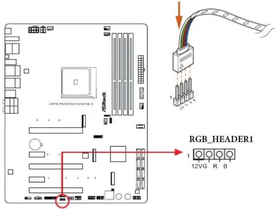
RGB LED Header (4-pin RGB_HEADER1) (see p.1, No. 28)
This RGB header is used to connect RGB LED extension cable which allows users to choose from various LED lighting effects.
Caution: Never install the RGB LED cable in the wrong orientation; otherwise, the cable may be damaged.
*Please refer to page 54 for further instructions on this header.
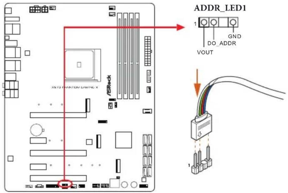
Addressable LED Header (3-pin ADDR_LED1) (see p.1, No. 29)
This header is used to connect Addressable LED extension cable which allows users to choose from various LED lighting effects.
Caution: Never install the Addressable LED cable in the wrong orientation; otherwise, the cable may be damaged.
*Please refer to page 55 for further instructions on this header.
2.7 Smart Switches
The motherboard has four smart switches: Power Button, Reset Button and Clear CMOS Buttons, allowing users to quickly turn on/off the system, reset the system or clear the CMOS values.
Power Button
(PWRBTN)
(see p.1, No. 21)

Power Button allows users to quickly turn on/off the system.
Reset Button
(RSTBTN)
(see p.1, No. 22)

Reset Button allows users to quickly reset the system.
Clear CMOS Buttons
(CLRCBTN1)
(see p.3, No. 15)
(CLRCBTN2)
(see p.1, No. 19)

Clear CMOS Buttons allow users to quickly clear the CMOS values.

This function is workable only when you power off your computer and unplug the power supply.
BIOS Flashback Button
(BIOS_FB1)
(see p.3, No. 18)
BIOS Flashback Switch allows users to flash the BIOS.
ASRock BIOS Flashback feature allows you to update BIOS without powering on the system, even without CPU.
To use the USB BIOS Flashback function, Please follow the steps below.
- Download the latest BIOS file from ASRock's website: http://www.asrock.com.
- Copy the BIOS file to your USB flash drive. Please make sure the file system of your USB flash drive must be FAT32.
- Extract BIOS file from the zip file.
- Rename the file to "creative.rom" and save it to the root directory of X: USB flash drive.
- Plug the 24 pin power connector to the motherboard. Then turn on the power supply's AC switch.
*There is no need to power on the system.
- Then plug your USB drive to the USB BIOS Flashback port.
- Press the BIOS Flashback Switch for about three seconds. Then the LED starts to blink.
- Wait until the LED stops blinking, indicating that BIOS flashing has been completed.
*If the LED light turns solid green, this means that the BIOS Flashback is not operating properly. Please make sure that you plug the USB drive to the USB BIOS Flashback port.
**If the LED does not light up at all then please disconnect power from the system and remove/disconnect the CMOS battery from the motherboard for several minutes. Reconnect power and battery and try again.
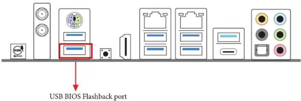
text_image
USB BIOS Flashback port2.8 Dr. Debug
Dr. Debug is used to provide code information, which makes troubleshooting even easier. Please see the diagrams below for reading the Dr. Debug codes.
| Code | Description |
| 0x10 | PEI_CORE_STARTED |
| 0x11 | PEI_CAR_CPU_INIT |
| 0x15 | PEI_CAR_NB_INIT |
| 0x19 | PEI_CAR_SB_INIT |
| 0x31 | PEI_MEMORY_INSTALLED |
| 0x32 | PEI_CPU_INIT |
| 0x33 | PEI_CPU_CACHE_INIT |
| 0x34 | PEI_CPU_AP_INIT |
| 0x35 | PEI_CPU_BSP_SELECT |
| 0x36 | PEI_CPU_SMM_INIT |
| 0x37 | PEI_MEM_NB_INIT |
| 0x3B | PEI_MEM_SB_INIT |
| 0x4F | PEI_DXE_IPL_STARTED |
| 0x60 | DXE_CORE_STARTED |
| 0x61 | DXE_NVRAM_INIT |
| 0x62 | DXE_SBRUN_INIT |
0x63 DXE_CPU_INIT
0x68 DXE_NB_HB_INIT
0x69 DXE_NB_INIT
0x6A DXE_NB_SMM_INIT
0x70 DXE_SB_INIT
0x71 DXE_SB_SMM_INIT
0x72 DXE_SB_DEVICES_INIT
0x78 DXE ACPI_INIT
0x79 DXE_CSM_INIT
0x90 DXE_BDS_STARTED
0x91 DXE_BDS_CONNECT_DRIVERS
0x92 DXE_PCI_BUS_BEGIN
0x93 DXE_PCI_BUS_HPC_INIT
0x94 DXE_PCI_BUS_ENUM
0x95 DXE_PCI_BUS_REQUEST_RESOURCES
0x96 DXE_PCI_BUS_ASSIGN_RESOURCES
0x97 DXE_CON_OUT_CONNECT
0x98 DXE_CON_IN_CONNECT
0x99 DXE_SIO_INIT
0x9A DXE_USB_BEGIN
0x9B DXE_USB_RESET
0x9C DXE_USB_DETECT
0x9D DXE_USB_ENABLE
0xA0 DXE_IDE_BEGIN
0xA1 DXE_IDE_RESET
0xA2 DXE_IDE_DETECT
0xA3 DXE_IDE_ENABLE
0xA4 DXE_SCSI_BEGIN
0xA5 DXE_SCSI_RESET
0xA6 DXE_SCSI_DETECT
0xA7 DXE_SCSI_ENABLE
0xA8 DXE_SETUP_VERIFYING_PASSWORD
0xA9 DXE_SETUP_START
0xAB DXE_SETUP_INPUT_WAIT
0xAD DXE_READY_TO_BOOT
0xAE DXE_LEGACY_BOOT
0xAF DXE_EXIT_BOOT_SERVICES
0xB0 RT_SET_VIRTUAL_ADDRESS_MAP_BEGIN
0xB1 RT_SET_VIRTUAL_ADDRESS_MAP_END
0xB2 DXE_LEGACY_OPROM_INIT
0xB3 DXE_RESET_SYSTEM
0xB4 DXE_USB_HOTPLUG
0xB5 DXE_PCI_BUS_HOTPLUG
0xB6 DXE_NVRAM_CLEANUP
0xB7 DXE_CONFIGURATION_RESET
0xF0 PEI_RECOVERY_AUTO
0xF1 PEI_RECOVERY_USER
0xF2 PEI_RECOVERY_STARTED
0xF3 PEI_RECOVERY_CAPSULE_FOUND
0xF4 PEI_RECOVERY_CAPSULE_LOADED
0xE0 PEI_S3_STARTED
0xE1 PEI_S3_BOOT_SCRIPT
0xE2 PEI_S3_VIDEO_REPOST
0xE3 PEI_S3_OS_WAKE
0x50 PEI_MEMORY_INVALID_TYPE
0x53 PEI_MEMORY_NOT_DETECTED
0x55 PEI_MEMORY_NOT_INSTALLED
0x57 PEI_CPU_MISMATCH
0x58 PEI_CPU_SELF_TEST_FAILED
0x59 PEI_CPU_NO_MICROCODE
0x5A PEI_CPU_ERROR
0x5B PEI_RESET_NOT_AVAILABLE
0xD0 DXE_CPU_ERROR
0xD1 DXE_NB_ERROR
0xD2 DXE_SB_ERROR
0xD3 DXE_ARCH_PROTOCOL_NOT_AVAILABLE
0xD4 DXE_PCI_BUS_OUT_OF_RESOURCES
0xD5 DXE_LEGACY_OPROM_NO_SPACE
0xD6 DXE_NO_CON_OUT
0xD7 DXE_NO_CON_IN
0xD8 DXE_INVALID_PASSWORD
0xD9 DXE_BOOT_OPTION_LOAD_ERROR
0xDA DXE_BOOT_OPTION_FAILED
0xDB DXE_FLASH_UPDATE_FAILED
0xDC DXE_RESET_NOT_AVAILABLE
0xE8 PEI_MEMORY_S3_RESUME_FAILED
0xE9 PEI_S3_RESUME_PPI_NOT_FOUND
0xEA PEI_S3_BOOT_SCRIPT_ERROR
0xEB PEI_S3_OS_WAKE_ERROR
2.9 M.2\_SSD (NGFF) Module Installation Guide (M2\_1)
The M.2, also known as the Next Generation Form Factor (NGFF), is a small size and versatile card edge connector that aims to replace mPCIe and mSATA. The Hyper M.2 Socket (M2_1) supports SATA3 6.0 Gb/s module and M.2 PCI Express module up to Gen4x4 (64 Gb/s) (with Raven Ridge and Pinnacle Ridge) or Gen3 x2 (16 Gb/s).
Installing the M.2_SSD (NGFF) Module
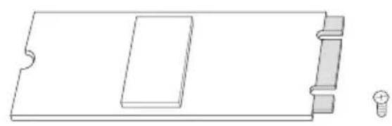
natural_image
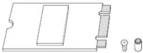
Pure technical line drawing of a rectangular component with internal structure and a small bolt symbol (no text or labels)Step 1
Prepare a M.2_SSD (NGFF) module and the screw.
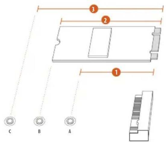
text_image
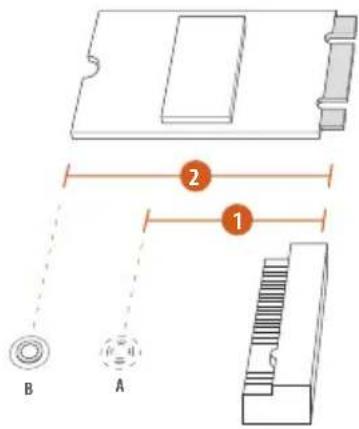
C B A 1 2 3Step 2
Depending on the PCB type and length of your M.2_SSD (NGFF) module, find the corresponding nut location to be used.
No. 1 2 3
Nut Location A B C
PCB Length 4.2cm 6cm 8cm
Module Type
Type 2242
Type2260
Type 2280
text_image
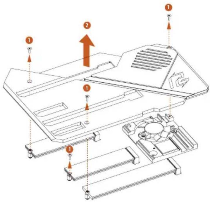
Technical diagram of a computer motherboard with numbered components and directional arrows indicating assembly or movement.Step 3
Before installing a M.2 (NGFF) SSD module, please loosen the screws to remove the M.2 heatsink.
*Please remove the protective films on the bottom side of the M.2 heatsink before you install a M.2 SSD module.
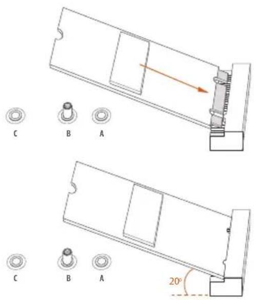
text_image
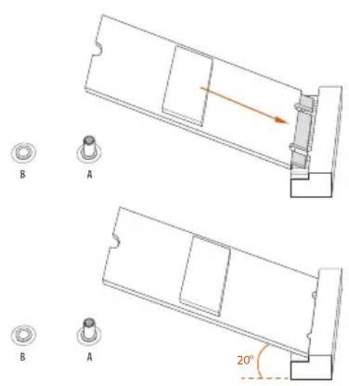
C B A C B A 20°Step 4
Prepare the M.2 standoff that comes with the package. Then hand tighten the standoff into the desired nut location on the motherboard. Align and gently insert the M.2 (NGFF) SSD module into the M.2 slot. Please be aware that the M.2 (NGFF) SSD module only fits in one orientation.
natural_image
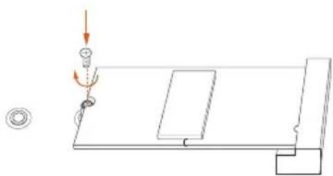
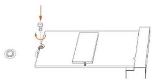
Pure technical diagram showing a mechanical setup with no text, numbers, or symbolsStep 5
Tighten the screw with a screwdriver to secure the module into place. Please do not overtighten the screw as this might damage the module.
M.2\_SSD (NGFF) Module Support List
| Vendor Interface P/N | |
| SanDisk PCIe SanDisk-SD6PP4M-128G( Gen2 x2) | |
| Intel PCIe INTEL 6000P-SSDPEKKF256G7 (nvme) | |
| Intel PCIe INTEL 6000P-SSDPEKKF512G7 (nvme) | |
| Intel PCIe SSDPEKKF512G7 NVME / 512GB | |
| Intel SATA 540S-SSDSCKKW240H6 / 240GB | |
| Kingston PCIe Kingston SHPM2280P2 / 240G (Gen2 x4) | |
| Samsung PCIe Samsung XP941-MZHPU512HCGL(Gen2x4) | |
| Samsung PCIe SM951 (NVME) / 512GB | |
| Samsung PCIe SM951 (MZHPV512HDGL) / 512GB | |
| ADATA SATA ADATA - AXNS381E-128GM-B | |
| ADATA PCIe ASX8000NP-512GM-C / 512GB | |
| ADATA PCIe ASX7000NP-512GT-C / 512GB | |
| ADATA SATA ASU800NS38-512GT-C / 512GB | |
| Crucial SATA Crucial-CT240M500SSD4-240GB | |
| ezlink SATA ezlink P51B-80-120GB | |
| Intel SATA INTEL 540S-SSDSCKKW240H6-240GB | |
| Kingston SATA Kingston SM2280S3G2/120G - Win8.1 | |
| Kingston SATA Kingston-RBU-SNS8400S3 / 180GD | |
| Kingston PCIe SKC1000/480G | |
| Kingston PCIe SKC1000/960GB NVME | |
| LITEON SATA LITEON LJH-256V2G-256GB (2260) | |
| PLEXTOR SATA PLEXTOR PX-128M6G-2260-128GB | |
| PLEXTOR SATA PLEXTOR PX-128M7VG-128GB | |
| PLEXTOR PCIe PX-512M8PeG/ 512GB | |
| SanDisk SATA SanDisk X400-SD8SN8U-128G | |
| SanDisk SATA Sandisk Z400s-SD8SNAT-128G-1122 | |
| SanDisk SATA SanDisk-SD6SN1M-128G | |
| Transcend SATA Transcend TS256GMTS800-256GB | |
| Transcend SATA TS512GMTS800 / 512GB | |
| V-Color SATA V-Color 120G | |
| V-Color SATA V-Color 240G | |
| WD SATA WD GREEN WDS240G1G0B-00RC30 | |
| WD PCIe WDS512G1X0C-00ENX0 (NVME) / 512GB |
For the latest updates of M.2_SSD (NFGG) module support list, please visit our website for details: http://www.asrock.com
2.10 M.2\_SSD (NGFF) Module Installation Guide (M2\_2)
The M.2, also known as the Next Generation Form Factor (NGFF), is a small size and versatile card edge connector that aims to replace mPCIe and mSATA. The Hyper M.2 Socket (M2_2) supports M.2 PCI Express module up to Gen4x4 (64 Gb/s).
Installing the M.2\_SSD (NGFF) Module
natural_image
Technical line drawing of a mechanical component with two small parts (no text or symbols)Step 1
This motherboard supports M.2_SSD (NGFF) module type 2260 and 2280 only. Prepare a proper PCB lenth of module, the screw and the standoff.
text_image
B A 1 2Step 2
Depending on the PCB type and length of your M.2_SSD (NGFF) module, find the corresponding nut location to be used.
No. 1 2
Nut Location A B
PCB Length 6cm 8cm
Module Type Type2260 Type 2280

text_image
Technical diagram of a computer motherboard with numbered components and directional arrows indicating assembly or movement.Step 3
Before installing a M.2 (NGFF) SSD module, please loosen the screws to remove the M.2 heatsink.
*Please remove the protective films on the bottom side of the M.2 heatsink before you install a M.2 SSD module.
text_image
B A B A 20°Step 4
Prepare the M.2 standoff that comes with the package. Then hand tighten the standoff into the desired nut location on the motherboard. Align and gently insert the M.2 (NGFF) SSD module into the M.2 slot. Please be aware that the M.2 (NGFF) SSD module only fits in one orientation.
natural_image
Pure technical diagram showing a mechanical setup with a lever and base plate, no text or symbols present.Step 5
Tighten the screw with a screwdriver to secure the module into place. Please do not overtighten the screw as this might damage the module.
M.2\_SSD (NGFF) Module Support List
Vendor Interface P/N
SanDisk PCIe SanDisk-SD6PP4M-128G( Gen2 x2)
Intel PCIe INTEL 6000P-SSDPEKKF256G7 (nvme)
Intel PCIe INTEL 6000P-SSDPEKKF512G7 (nvme)
Intel PCIe SSDPEKKF512G7 NVME / 512GB
Kingston PCIe Kingston SHPM2280P2 / 240G (Gen2 x4)
Samsung PCIe Samsung XP941-MZHPU512HCGL(Gen2x4)
Samsung PCIe SM951 (NVME) / 512GB
Samsung PCIe SM951 (MZHPV512HDGL) / 512GB
ADATA PCIe ASX8000NP-512GM-C / 512GB
ADATA PCIe ASX7000NP-512GT-C / 512GB
Kingston PCIe SKC1000/480G
Kingston PCIe SKC1000/960GB NVME
PLEXTOR PCIe PX-512M8PeG/ 512GB
WD PCIe WDS512G1X0C-00ENX0 (NVME) / 512GB
For the latest updates of M.2_SSD (NFGG) module support list, please visit our website for details: http://www.asrock.com
2.11 M.2\_SSD (NGFF) Module Installation Guide (M2\_3)
The M.2, also known as the Next Generation Form Factor (NGFF), is a small size and versatile card edge connector that aims to replace mPCIe and mSATA. The Hyper M.2 Socket (M2_3) supports M.2 SATA3 6.0 Gb/s module and M.2 PCI Express module up to Gen4x4 (64 Gb/s).
* If M2_3 is occupied, PCIE5 slot will be disabled.
Installing the M.2\_SSD (NGFF) Module
natural_image
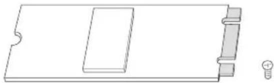
Pure technical line drawing of a rectangular component with a slot and base, no text or symbols presentStep 1
Prepare a M.2_SSD (NGFF) module and the screw.
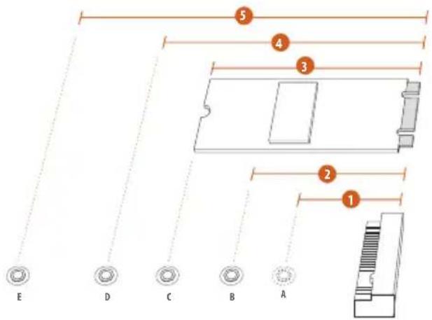
text_image
5 4 3 2 1 E D C B AStep 2
Depending on the PCB type and length of your M.2_SSD (NGFF) module, find the corresponding nut location to be used.
No.12345
| Nut Location A B C D E | |||||
| PCB Length | 3cm | 4.2cm | 6cm | 8cm | 11cm |
| Module Type | Type2230 | Type 2242 | Type2260 | Type 2280 | Type 22110 |

text_image
Technical diagram of a device with numbered components and directional arrows indicating assembly or installation steps.Step 3
Before installing a M.2 (NGFF) SSD module, please loosen the screws to remove the M.2 heatsink.
*Please remove the protective films on the bottom side of the M.2 heatsink before you install a M.2 SSD module.
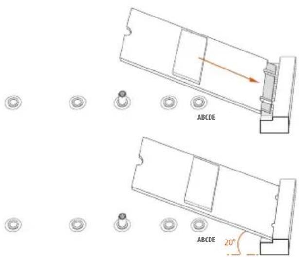
text_image
ABCDE ABCDE 20°Step 4
Prepare the M.2 standoff that comes with the package. Then hand tighten the standoff into the desired nut location on the motherboard. Align and gently insert the M.2 (NGFF) SSD module into the M.2 slot. Please be aware that the M.2 (NGFF) SSD module only fits in one orientation.
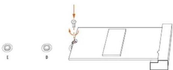
natural_image
Technical diagram showing a mechanical assembly with labeled components E and D, no readable text or symbols present.Step 5
Tighten the screw with a screwdriver to secure the module into place. Please do not overtighten the screw as this might damage the module.
M.2\_SSD (NGFF) Module Support List
| Vendor Interface P/N | ||
| SanDisk PCIe SanDisk-SD6PP4M-128G( Gen2 x2) | ||
| Intel PCIe INTEL 6000P-SSDPEKKF256G7 (nvme) | ||
| Intel PCIe INTEL 6000P-SSDPEKKF512G7 (nvme) | ||
| Intel PCIe SSDPEKKF512G7 NVME / 512GB | ||
| Intel SATA 540S-SSDSCKKW240H6 / 240GB | ||
| Kingston PCIe Kingston SHPM2280P2 / 240G (Gen2 x4) | ||
| Samsung PCIe Samsung XP941-MZHPU512HCGL(Gen2x4) | ||
| Samsung PCIe SM951 (NVME) / 512GB | ||
| Samsung PCIe SM951 (MZHPV512HDGL) / 512GB | ||
| ADATA SATA ADATA - AXNS381E-128GM-B | ||
| ADATA PCIe ASX8000NP-512GM-C / 512GB | ||
| ADATA PCIe ASX7000NP-512GT-C / 512GB | ||
| ADATA SATA ASU800NS38-512GT-C / 512GB | ||
| Crucial SATA Crucial-CT240M500SSD4-240GB | ||
| ezlink SATA ezlink P51B-80-120GB | ||
| Intel SATA INTEL 540S-SSDSCKKW240H6-240GB | ||
| Kingston SATA Kingston SM2280S3G2/120G - Win8.1 | ||
| Kingston SATA Kingston-RBU-SNS8400S3 / 180GD | ||
| Kingston PCIe SKC1000/480G | ||
| Kingston PCIe SKC1000/960GB NVME | ||
| LITEON SATA LITEON LJH-256V2G-256GB (2260) | ||
| PLEXTOR SATA PLEXTOR PX-128M6G-2260-128GB | ||
| PLEXTOR SATA PLEXTOR PX-128M7VG-128GB | ||
| PLEXTOR PCIe PX-512M8PeG/ 512GB | ||
| SanDisk SATA SanDisk X400-SD8SN8U-128G | ||
| SanDisk SATA Sandisk Z400s-SD8SNAT-128G-1122 | ||
| SanDisk SATA SanDisk-SD6SN1M-128G | ||
| Transcend SATA Transcend TS256GMTS800-256GB | ||
| Transcend SATA TS512GMTS800 / 512GB | ||
| V-Color SATA V-Color 120G | ||
| V-Color SATA V-Color 240G | ||
| WD SATA WD GREEN WDS240G1G0B-00RC30 | ||
| WD PCIe WDS512G1X0C-00ENX0 (NVME) / 512GB |
For the latest updates of M.2_SSD (NFGG) module support list, please visit our website for details: http://www.asrock.com
2.12 ASRock Polychrome SYNC
ASRock Polychrome SYNC is a lighting control utility specifically designed for unique individuals with sophisticated tastes to build their own stylish colorful lighting system. Simply by connecting the LED strip, you can customize various lighting schemes and patterns, including Static, Breathing, Strobe, Cycling, Music, Wave and more.
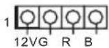
Connecting the LED Strip
Connect your RGB LED strip to the RGB LED Header (RGB_HEADER1) on the motherboard.
text_image
X578 PHANTOM GAMING X ASRock RGB_HEADER1 12VG R B 1 12G R B
- Never install the RGB LED cable in the wrong orientation; otherwise, the cable may be damaged.
- Before installing or removing your RGB LED cable, please power off your system and unplug the power cord from the power supply. Failure to do so may cause damages to motherboard components.

- Please note that the RGB LED strips do not come with the package.
- The RGB LED header supports standard 5050 RGB LED strip (12V/G/R/B), with a maximum power rating of 3A (12V) and length within 2 meters.
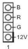
Connecting the Addressable RGB LED Strip
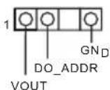
Connect your Addressable RGB LED strip to the Addressable LED Header (ADDR_LED1) on the motherboard.
text_image
ADDR_LED1 1 GND DO_ADDR VOUT XS70 PHANTOM GAMNC X ASRock
- Never install the RGB LED cable in the wrong orientation; otherwise, the cable may be damaged.
- Before installing or removing your RGB LED cable, please power off your system and unplug the power cord from the power supply. Failure to do so may cause damages to motherboard components.

- Please note that the RGB LED strips do not come with the package.
- The RGB LED header supports WS2812B addressable RGB LED strip (5V/Data/GND), with a maximum power rating of 3A (5V) and length within 2 meters.
ASRock Polychrome SYNC Utility
Now you can adjust the RGB LED color through the ASRock RGB LED utility. Download this utility from the ASRock Live Update & APP Shop and start coloring your PC style your way!
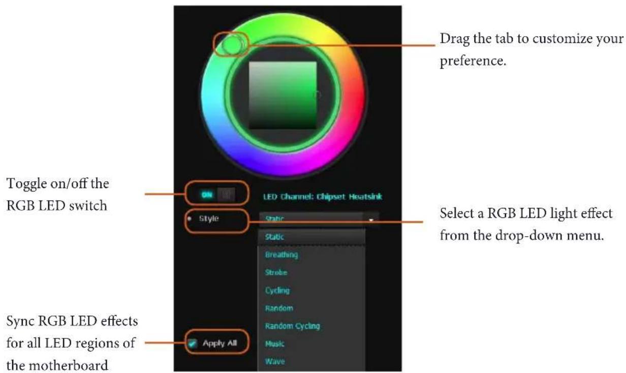
text_image
Drag the tab to customize your preference. Toggle on/off the RGB LED switch Select a RGB LED light effect from the drop-down menu. Sync RGB LED effects for all LED regions of the motherboard LED Channel: Chipset Heatsink Style Static Static Breathing Stroke Cycling Random Random Cycling Music Wave Apply All1 Einleitung
text_image
Diagram showing various electronic devices with labels and icons, including speaker, audio, and display units.USB-BIOS-Flashback-Port
1 Introduction
1 x 2.5 LAN Gigabit 10/100/1000/2500 Mb/s
(Dragon RTL8125AG)
- 1 ranura PCI Express 4.0 x16 (simple a x4 (PCIE5))*
1 x Intel Gigabit LAN 10/100/1000 Mb/s (1 x Intel\* I211AT):
CPU Seri AMD Ryzen (Pinnacle Ridge)
- 3 x Slot PCI Express x16 (PCIE1/PCIE3/PCIE5: satu pada Gen3x16 (PCIE1); dua pada Gen3x8 (PCIE1)/Gen3x8 (PCIE3); tiga pada Gen3x8 (PCIE1)/Gen3x8 (PCIE3)/Gen4x4 (PCIE5))*
If you need to contact ASRock or want to know more about ASRock, you're welcome to visit ASRock's website at http://www.asrock.com; or you may contact your dealer for further information. For technical questions, please submit a support request form at https://event.asrock.com/tsd.asp
ASRock Incorporation
2F., No.37, Sec. 2, Jhongyang S. Rd., Beitou District,
Taipei City 112, Taiwan (R.O.C.)
ASRock EUROPE B.V.
Bijsterhuizen 11-11
6546 AR Nijmegen
The Netherlands
Phone: +31-24-345-44-33
Fax: +31-24-345-44-38
ASRock America, Inc.
13848 Magnolia Ave, Chino, CA91710
U.S.A.
Phone: +1-909-590-8308
Fax: +1-909-590-1026
DECLARATION OF CONFORMITY
Per FCC Part 2 Section 2.1077(a)

Responsible Party Name: ASRock Incorporation
Address: 13848 Magnolia Ave, Chino, CA91710
Phone/Fax N o: +1-909-590-8308/+1-909-590-1026
hereby declares that the product
Product Name : Motherboard
Model Number : X570 Phantom Gaming X
Conforms to the following specifications:
☒ FCC Part 15, Subpart B, Unintentional Radiators
Supplementary Information:
This device complies with part 15 of the FCC Rules. Operation is subject to the following two conditions: (1) This device may not cause harmful interference, and (2) this device must accept any interference received, including interference that may cause undesired operation.
Representative Person's Name: James
Signature :

Date : May 12, 2017
EU Declaration of Conformity
ASRock®
For the following equipment:
Motherboard
(Product Name)
X570 Phantom Gaming X / ASRock
(Model Designation / Trade Name)
ASRock Incorporation
(Manufacturer Name)
2F., No.37, Sec. 2, Jhongyang S. Rd., Beitou District, Taipei City 112, Taiwan (R.O.C.)
(Manufacturer Address)
EMC — Directive 2014/30/EU (from April 20th, 2016)
□ EN 55022:2010/AC:2011 Class B
EN 55024:2010/A1:2015
EN 55032:2012+AC:2013 Class B
EN 61000-3-3:2013
EN 61000-3-2:2014
RED-Directive 2014/53/EU
□ EN 300 328 V2.1.1 EN 301 489-17 V3.1.1
×
□ EN 301 893 V2.1.1
□ EN 301 489-3 V2.1.1
□ EN 300 220 V3.1.1
□LVD — Directive 2014/35/EU (from April 20th, 2016)
□ EN 60950-1:2011+ A2:2013
□ EN 60950-1:2006/A12:2011
☒ RoHS — Directive 2011/65/EU
CE marking
CE
(EU conformity marking)
ASRock EUROPE B.V.
(Company Name)
Bijsterhuizen 1111 6546 AR Nijmegen The Netherlands
(Company Address)
Person responsible for making this declaration:

(Name, Surname)
A.V.P
(Position / Title)
June 28, 2019
(Date)
P/N: 15G062163002AK V1.2