MZKA780 - Air Conditioning Monzana - Free user manual and instructions
Find the device manual for free MZKA780 Monzana in PDF.
| Product type | Portable monobloc air conditioner |
| Brand | Monzana |
| Model | MZKA780 |
| Dimensions (L x W x H) | 34 x 35.4 x 70 cm |
| Weight | 20.5 kg |
| Power supply | 220-240 V / 50 Hz |
| Rated current | 3.5 A |
| Cooling power | 2.1 kW |
| Dehumidification capacity | 19.2 L/24h |
| Refrigerant | R290 (propane) |
| Refrigerant charge | 140 g |
| Maximum air flow | 360 m³/h |
| Noise level | ≤ 65 dB(A) |
| Operating modes | Cooling, fan, dehumidification, energy saving mode (Sleep) |
| Minimum room area | > 7 m² |
| Programmable timer | 1-24 hours |
| Remote control | Yes, with 2xAAA batteries |
| Air filter | Washable, clean every 2 weeks |
| Condensate drainage | Automatic evaporation in cooling mode; manual drainage in dehumidification mode |
| Casters | Yes, for easy mobility |
| Ambient temperature range | 16-32 °C |
| Temperature setting range | 16-32 °C |
| Automatic defrost | Yes, at low ambient temperature |
| Overload protection | 3-minute delay before compressor restart |
| Intended use | Household, indoor only |
Frequently Asked Questions - MZKA780 Monzana
User questions about MZKA780 Monzana
0 question about this device. Answer the ones you know or ask your own.
Ask a new question about this device
Download the instructions for your Air Conditioning in PDF format for free! Find your manual MZKA780 - Monzana and take your electronic device back in hand. On this page are published all the documents necessary for the use of your device. MZKA780 by Monzana.
USER MANUAL MZKA780 Monzana
natural_image
White portable air conditioner unit with ventilation slots and wheels (no visible text or symbols)Klimaanlage
ANLEITUNG
EN Appliance shall be installed, operated and stored in a room with floor area larger than 8 m ^2 .
3.4 STANDORT WÄHLEN
natural_image
Technical line drawing of a cylindrical mechanical component with concentric grooves (no text or symbols)natural_image
Three vertical metal bars with cutouts and a separate close-up of a small object (no text or symbols visible)natural_image
Simple line drawing of a window with an arrow pointing to the left pan, no text or symbols present.natural_image
Illustration of a portable air conditioner unit with a handle and ventilation grille (no text or symbols)natural_image
Illustration of a portable air conditioner unit with a window view (no text or symbols)natural_image
Close-up of a mechanical component with a knob and lever (no visible text or symbols)natural_image
Close-up of a black mechanical component with a cylindrical protrusion and a small circular feature, no visible text or symbols.You have made a good choice by purchasing one of our branded products. In order to enjoy the product for as long as possible and to ensure safe handling, please observe the assembly and operating instructions overleaf. To ensure the desired high quality standard, our articles are subject to regular controls and of course always meet the high requirements of the European Union. Even the best products can have defects, e.g. due to external circumstances. We stand by our quality promise and offer you the best possible service. Should a problem occur, please contact our trained staff for whatever kind of service, complaints and technical support you require.
TABLE OF CONTENTS
Notes on the operating manual 23
Safety 24
Information about the unit....27
Assembly and installation 28
Operation....31
Cleaning and care....34
Storage and transport 35
Errors and faults....36
Technical Data....37
Maintenance 38
Disposal....40
SYMBOLS

IMPORTANT
Thoroughly read the manual in full before using the unit for the first time. Keep this manual for future reference. If you pass on the product one day, be sure to hand over this manual as well.

PRODUCT MODIFICATION
Never make modifications to the product! Modifications will invalidate the warranty and the product may become unsafe or – in the worst-case scenario – even dangerous. Ensure that this product is fully assembled before use.

ATTENTION!
Observe the safety instructions and assembly instructions to avoid the risk of injury or damage to the product.

WARNING
This unit uses a flammable refrigerant (R920).
If this refrigerant leaks and comes into contact with fire or heating elements, it forms dangerous fumes and creates a fire hazard.

WARNING – ELECTRICAL VOLTAGE
Work on electrical components may only be carried out by an authorised specialist company!

RISK OF SUFFOCATION!
Keep small parts and packaging material away from children! Check the scope of delivery to ensure the unit is complete. Subsequent complaints cannot be accepted. Check all the elements and parts for damage. Despite careful checks, even the best goods can potentially be damaged in transit. Do not assemble your product in such a situation. Defective parts can cause hazards and harm to health.

WARNING
Any person working on a refrigerant system must hold a valid certificate issued by an industry-accredited testing organisation that authorises their expertise to safely handle refrigerants according to an industry-recognised testing specification.

WARNING
Maintenance work may only be carried out in accordance with the unit manufacturer's recommendations. Maintenance and repair work that requires the involvement of other specialists must be carried out under the supervision of the person responsible for the use of flammable refrigerants.
Safety instructions on the unit
Do not remove any safety signs on the unit. Keep the safety signs, stickers and labels in a legible condition.
The following safety instructions are attached to the unit
WARNING • WARNUNG • ATTENTION
EN Appliance shall be installed, operated and stored in a room with floor area larger than 8 m ^2 .
Warning: The unit must be set up, operated and stored in a room with an appropriate floor space. See the technical data regarding this matter.
!!! ACHTUNG !!!
Staff qualification for operation
- This unit may be used by children over the age of 8 and by individuals with reduced physical sensory or mental capabilities or a lack of experience and knowledge, provided that they are supervised or have received instructions on the safe use of the unit and understand the risks involved. Children may not play with the unit. Do not allow children to clean the unit without supervision. Maintenance must only be carried out by specialist staff.
- Individuals who have to use this unit must be aware of the dangers that arise when working with electrical equipment, especially in a damp environment.
- Individuals who must use this unit have read and understood the operating manual.
Staff qualification for maintenance and repair
- Any person working on the refrigerant circuit must have a certificate of competence issued by an industry-accredited body demonstrating their expertise in the safe handling of refrigerants by means of a method known in the industry.
- If maintenance and repair work requires the assistance of other individuals, the person trained in handling flammable refrigerants should constantly monitor the work.
Units – safety instructions
- The refrigerant circuit is sealed. Only a qualified technician may carry out maintenance!
- The refrigerant must not be discharged into the air.
• R-290 (propane) is flammable and heavier than air. - It accumulates in low areas initially, but can be circulated by the fans.
- No untrained personnel should attempt to determine the cause if propane gas is present, or if there is even a suspicion that propane gas is present.
- The propane gas used in the plant is odourless.
- The lack of smell does not indicate that no gas is escaping.
- If a leak is detected, immediately evacuate everyone from the surrounding area, ventilate the room and contact the local fire brigade to inform them that propane gas has leaked.
- Do not allow anyone to return to the room until a qualified service technician has arrived and advised that it is safe to do so.
- Do not use naked flames, cigarettes or other possible ignition sources inside or near the equipment.
- The components used are intended for propane gas. They may only be replaced by spare parts of the same type.
FAILURE TO HEED THIS WARNING MAY RESULT IN EXPLOSION, DEATH, PERSONAL INJURY AND PROPERTY DAMAGE.
1.1 SAFETY PRECAUTIONS DURING MAINTENANCE AND REPAIR
This unit does not contain any components inside that can be repaired or maintained by lay individuals. The entire refrigerant circuit is a hermetically sealed system and may only be maintained and repaired by companies specialising in refrigeration and air conditioning technology.
1.2 RESIDUAL RISKS

Danger
Natural refrigerant – propane (R290)!
H220 – Extremely flammable gas.
H280 – Contains gas under pressure; may explode if heated.
P210 – Keep away from heat, hot surfaces, sparks, open flames and other ignition sources. No smoking.
P377 – Leaking gas fire – do not extinguish unless leak can be stopped safely.
P410+P403 – Protect from sunlight. Store in a well ventilated place.

Warning – electrical voltage
Work on electrical components may only be carried out by an authorised specialist company!

Warning – electrical voltage
Before carrying out any work on the unit, remove the mains plug from the mains socket!
Unplug the power cord from the mains socket by grasping the mains plug.

Warning
Dangers can arise from this unit if it is used improperly or for a purpose other than that intended by untrained individuals! Observe the staff qualifications!

Warning
The unit is not a toy and should not be handled by children.

Warning
Danger of suffocation!
Do not leave the packaging material lying around carelessly. It could become a dangerous toy for children.
2 OPERATIONAL PRECAUTIONS
WARNING – to reduce the risk of fire, electric shock, personal injury or property damage:
- If the power cord is damaged, it must be replaced by the manufacturer, its Customer Service Team or similarly qualified individuals to avoid any danger.
- Always connect the unit to a power source with the same voltage, frequency and power rating as indicated on the product label.
• Always use an earthed socket. - Unplug the power cord when cleaning the unit or when it is not in use.
- Do not operate the unit with wet hands. Take care not to spill water on the unit.
- The unit must not be immersed in water or exposed to rain, moisture or other liquids.
- Do not leave the unit running unattended. The unit must not be tilted or turned upside-down.
- Do not remove the mains plug while the unit is in operation.
- Do not remove the mains plug from the socket by pulling the power cord.
- Do not use an extension cable or an adapter plug.
- Do not place any objects on the unit.
- Do not climb or sit on the unit.
- Do not insert fingers or other objects into the air outlet.
- Do not touch the unit's air inlet or the aluminium ribs.
- Do not operate the unit if it has been dropped, damaged or is showing signs of malfunction.
- Do not clean the unit with chemicals.
-
Ensure that the unit is far away from fire and flammable or explosive objects.
-
The unit must be installed in accordance with national electrical installation regulations.
- Do not use any agents other than those recommended by the manufacturer to speed up the defrosting process or for cleaning.
- The unit must be stored in a room where there is no continuously operating system with high temperatures > 450°C (e.g. naked flames, a gas unit in operation or an electric heater in operation).
- The unit must be stored so that no mechanical damage can occur.
- It must not be cut up or burned even after use.
• Note that refrigerants may not have an odour. - The pipes must be protected from mechanical damage and must not be installed in a room without ventilation if it is smaller than stated in the technical data.
- Necessary ventilation openings must be kept free of obstacles.
- The unit must be stored in a well-ventilated room where the area corresponds to the room area specified for operation.
Please contact your local specialist dealer if you still have unanswered questions or need help.

INTENDED USE
Our powerful mobile air conditioners are excellent cooling systems for individual rooms and ensure a pleasant living atmosphere on your premises. They also have a ventilation and dehumidification function to circulate air and remove moisture. They are self-contained systems that do not require permanent equipment. So you can always move them to the room where you need them most. These systems are often used in kitchens, lounges, computer rooms, garages and many other areas where installing an outdoor unit with air conditioning is only possible to a limited extent.
The eco-friendly R290 is used as refrigerant. R290 has no harmful effects on the ozone layer (ODP), a negligible greenhouse effect (GWP) and is available worldwide. Due to its efficient energy properties, R290 is an excellent refrigerant for this application. The refrigerant's high flammability means that special safety precautions must be taken.
The unit is designed exclusively for cooling, ventilating, heating and dehumidifying indoor air, in compliance with the technical specifications.
Use the product only for the purpose it is intended for. The manufacturer accepts no liability for damage caused by unintended use. Any modification to the product may negatively impact safety, cause hazards and invalidate the warranty.
Only suitable for domestic use; not for commercial use.
3. COMMISSIONING
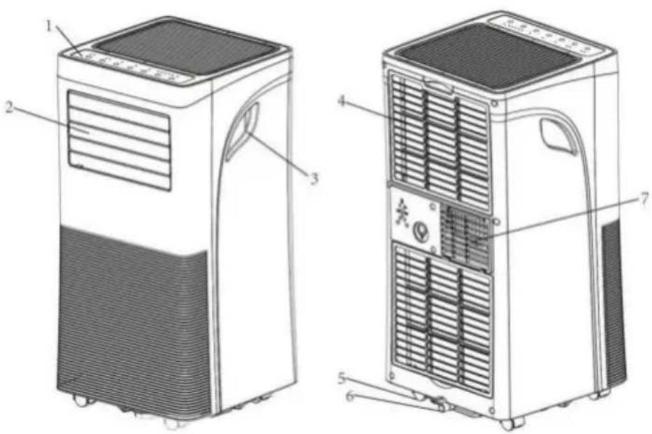
3.1 IMAGE OF THE PRODUCT
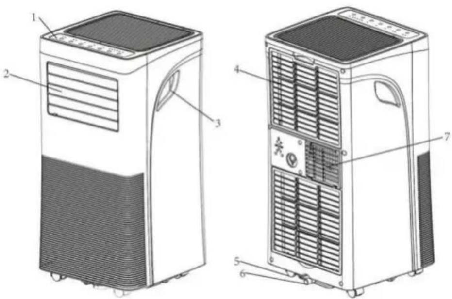
| 1 | Control panel | 4 | Air inlet with air filter | 6 | Condensate drain |
| 2 | Air outlet with adjustable louvre | 5 | Swivel castor | 7 | Exhaust air |
| 3 | Handle | ||||
Note: Schematic diagram of the unit.
3.2 PROPERTIES
- Powerful and compact with cooling, heating, dehumidification and ventilation functions.
- Temperature setting and display
- LED digital display
- Electronic control with built-in timer, energy saving mode
- Automatic condensate evaporation for better efficiency
- Automatic switch-off when the condensate container is full
- Automatic restart in the event of power failure
- Automatic defrost function at low room temperatures.
-
Remote control
-
Two-stage fan
- Swivel castors for easier mobility
- Controlling the unit using the TUYA app (optional)
3.3 UNPACKING INSTRUCTIONS
Open the box and remove the unit and accessories.
After unpacking the unit, please check it for damage or scratches
Accessories:
- Exhaust air hose
- Hose connector
- Adapter for the window kit
- Remote control
- Window kit
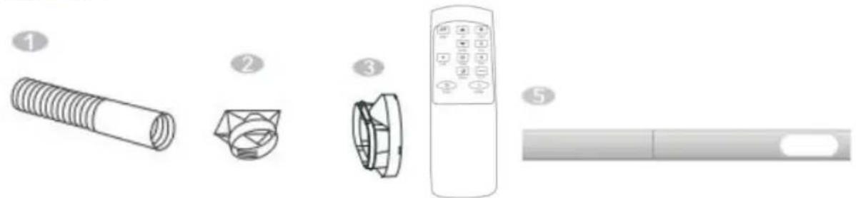
natural_image
Illustration of five different home appliances and a remote control device, labeled 1 to 5 (no text or symbols on the devices themselves)3.4 SELECTING A LOCATION
If the system has been tilted more than 45^ , leave it upright for at least 12 hours before commissioning.
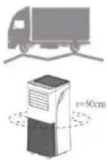
- Place the unit on a solid, horizontal surface, leaving at least 50 cm of free space around the unit for good air circulation.
- Do not place the unit in the immediate vicinity of walls, curtains or other objects that could block the air inlet and outlet. Ensure that the air inlet and outlet remain free of obstacles.
- The unit must never be installed where it could be endangered by the following:
Heat sources such as radiators, heat storage units, stoves or other products that generate heat
Direct sunlight
Mechanical vibrations or shocks
Excessive dust
➢ Insufficient ventilation, e.g. in a cupboard or bookcase
Uneven surface

WARNING!
The system must be installed in rooms that meet the specified room size; see the technical data regarding this matter.
The system may not be installed in a place where flammable gas could escape.
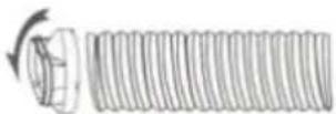
3.5 CONNECTING THE EXHAUST AIR HOSE
The air conditioner must be vented to the outside so that the exhaust air coming from the unit and containing waste heat and moisture can escape from the room.
Do not replace or lengthen the exhaust hose, as this may damage the unit.
Step 1: Connect the hose connector to one end of the exhaust hose.
natural_image
Technical line drawing of a cylindrical mechanical component with concentric grooves (no text or symbols)Step 2: Connect the adapter for the window kit to the other end of the exhaust air hose.
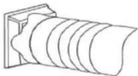
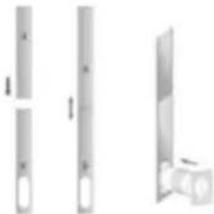
Step 3: Adjust the adjustable window kit by the length of your window. Connect the exhaust air hose to the window kit.
natural_image
Three vertical metallic bars with cutouts, shown from different angles (no text or symbols)Step 4: Close the window to secure the kit in place. The window kit must be held firmly in place. If necessary, secure the window kit with additional means. It is advisable to seal the space between the adapter and the window sides for maximum efficiency.
natural_image
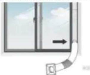
Simple line drawing of a window with an arrow indicating direction, no text or symbols presentStep 5: Connect the hose connector to the unit's exhaust air outlet.
natural_image
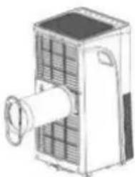
Illustration of a portable air conditioner unit with cooling fins and a central fan (no text or symbols)Step 6: Adjust the length of the flexible exhaust hose and avoid bends in the hose.
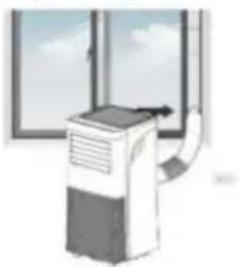
natural_image
Illustration of a portable air conditioner unit with a window view (no text or symbols)Step 7: Align the ventilation grilles with the air outlet, then switch on the unit.
4. OPERATION

REMOVE THE PROTECTIVE FILM BEFORE USE.
4.1 CONTROL PANEL AND DISPLAY
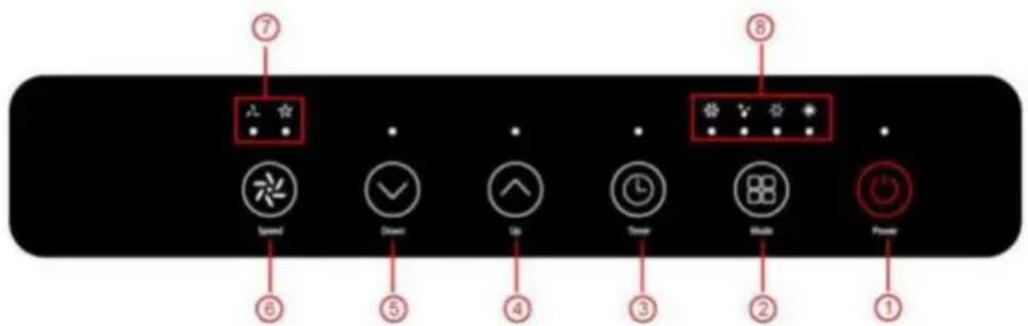
| 1 | POWER | Press this button to switch the unit on or off. |
| 2 | MODE | Press the Mode button to switch the operating mode between fan, cooling, heating and dehumidifier. |
| 3 | TIMER | Defines a time that the unit automatically starts or stops at. |
| 4 | UP | To increase the desired temperature (16°C~32°C) or set the timers. |
| 5 | DOWN | To lower the temperature to the desired value or set the timers. |
| 6 | SPEED | Press the button to switch the fan speed between HIGH and LOW. |
| 7 | Display for fan speed (FAN SPEED) | Indicates high and low fan speed |
| 8 | MODE display | Displays the operating mode: cooling, dehumidification, ventilation or heating. |
4.2 SETTINGS
4.2.1 SWITCHING ON AND OFF
- Press the POWER button to switch on the unit.
- The unit runs in FAN mode by default.
- Select the desired operating mode with the MODE button.
- Press POWER again to switch off the unit
The unit has five operating modes: cooling, drying, ventilation, heating, energy-saving mode.
A. COOLING THE ROOM
- Select the cooling mode to lower the temperature in your room.
- Press the MODE button several times until the COOL operating mode's LED lights up.
- Press the Up/Down button to set the temperature displayed on the screen. The temperature can be set between 16°C and 32°C.
- Press the SPEED button repeatedly until the desired speed's display lights up.
- The inner ventilation louvre is adjusted manually to control the direction of the air flow horizontally.
Note: The system is switched off when the room temperature is lower than the selected temperature.
B. HEATING THE ROOM (OPTIONAL ONLY FOR THE MZKA1000 FUNCTION UNIT)
- Press the MODE button repeatedly until the HEAT mode LED lights up.
- By pressing the Up/Down button, the temperature can be set higher than the room temperature. The fan speed can also be adjusted.
Note: The exhaust air hose must be connected to the unit for continuous operation.
C. ROOM VENTILATION
- Press the MODE button several times until the FAN mode LED lights up.
- In ventilation mode, the room air is circulated but not cooled.
- The desired fan speed can be selected by repeatedly pressing the SPEED button.
D. DRYING THE ROOM
- Press the MODE button on the control panel or remote control. The LED for DRY mode lights up. The fan speed cannot be adjusted. The user should connect the hose to the drain outlet on the underside of the unit.
Note: In this mode, the fan speed is switched to a low speed and cannot be adjusted.
E. SLEEP MODE: THIS FUNCTION CAN ONLY BE PERFORMED WITH A REMOTE CONTROL.
The energy-saving and sleep mode can be activated in both cooling and heating mode.
- In cooling mode:
After 1 hour, the preset temperature is increased by 1^ C, and by a further 1^ C an hour later.
• In heating mode (Optional only for the MZKA1000 function unit):
After 1 hour, the preset temperature is decreased by 1^ C, and by a further 1^ C an hour later. The temperature is then kept constant for 10 hours. And all the indicator lights are slowly dimmed until they turn dark. The fan will switch to a low speed to ensure quiet operation. This function cannot be changed.
4.2.3 TIMER SETTING (1 HOUR - 24 HOURS)
The timer can be operated in two different ways:
| To switch off(When the power is switched on) |  | Press the Timer button to switch on the timer function |  | Press Up/Down repeatedly to set the delay until the switch-off time |
| To switch on(When the power is switched off) |  | Press the Timer button to switch on the timer function |  | Press Up/Down repeatedly to set the delay until the switch-on time |
| Cancel the timer |  | Repeatedly press Up/Down until the LED shows '00'.Note: Pressing the POWER button will also end the timer setting | ||
4.2.4 AUTOMATIC DEFROSTING
Ice can form on the evaporator during operation at low room temperatures. The unit starts defrosting automatically and the POWER LED flashes. The defrost function is controlled as follows: This process can take up to 30 minutes depending on environmental conditions.
4.2.5 CONTROLLING THE UNIT USING THE TUYA APP (OPTIONAL ONLY FOR THE MZKA1000 FUNCTION UNIT)
Use is subject to a separate license agreement with the developer. This requires a device that can run the app and supports Bluetooth 4.0, as well as an internet connection over 2.4 GHz or 5 GHz WLAN or mobile data. To find out if the app is compatible, search for 'TUYA' in the iOS App Store or Google Play Store. Standard rates for data and messaging services may apply.
The Bluetooth® word mark and logos are registered trademarks of Bluetooth SIG, Inc., and any use of such marks by DEUBA is under license.
Preparation:
- download the Tuya Smart Life app from the Playstore
- Keep the WiFi password ready
• The smartphone/tablet and the air conditioner must be within range of the WiFi in use - Open the app and register.
Link:
- Open the app
- Select "add device"
-
Select "manual" - "large household device" - "air conditioner"
-
Enter the WiFi password
- Plug the air conditioner into the mains socket
- Confirm that the display is flashing quickly. (the module used may mean that it flashes slowly. confirm anyway)
- Tap continue
- The device is automatically recognised
Unlink:
If you wish to operate the device via another WiFi.
- Remove the device from the list in the app
- Press the timer >3 seconds
- Pull the mains plug
If linking fails:
- Ensure that the WiFi is not working in the 2.5 GHz area
• Unplug the air conditioner - Wait 30 seconds
- Plug in the air conditioner again
- Press the timer button >3 seconds
4.2.6 OVERLOAD PROTECTION
In the event of a power failure, a three-minute delay before the compressor restarts is provided to protect the compressor.
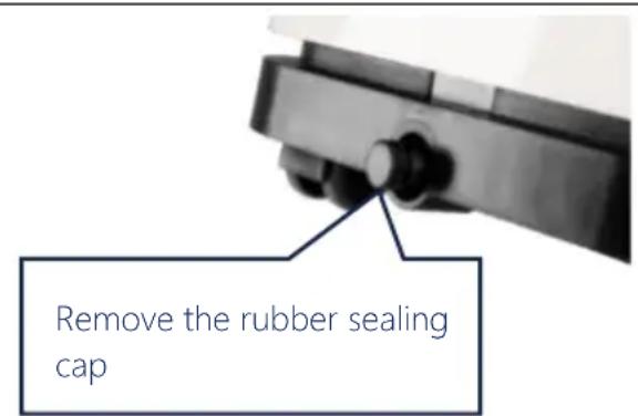
4.3 DRAINAGE
The automatic evaporation system uses the collected condensate to cool the condenser coils for more efficient performance. It is not necessary to empty the drainage container in cooling mode, except in drying mode and under highly humid conditions. The condensate evaporates at the condenser and is discharged through the exhaust hose.
For continuous operation or unattended operation in drying and heating mode, the connected drain hose must be connected to the unit. The condensate can be automatically directed into a bucket or drain by the gravity principle.
- Switch off the unit.
- Remove and store the outlet opening's plug.
- Connect the drain hose properly and ensure that it is not kinked and is free of obstacles.
- Place the hose outlet over a drain or bucket and ensure that the water
| can flow out of the unit without obstruction.The end of the hose must not be immersed in water. | 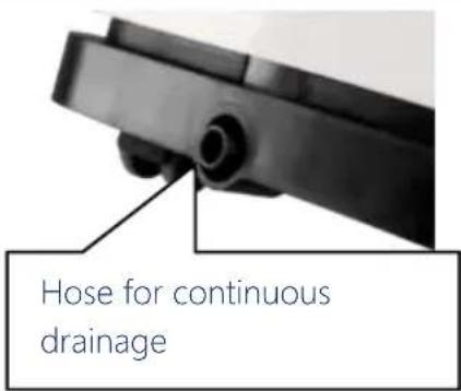 |
| To avoid spilling water:Since the negative pressure of the drain pan for condensate is high, lay the drain hose downwards towards the floor. The angle of inclination should exceed 20 degrees.Straighten the hose to avoid creating a siphon. | |

5. CLEANING AND CARE INSTRUCTIONS
5.1 CLEANING AND CARE
Cleaning the air filter (every two weeks)
Dust deposits on the filter and restricts air circulation. The restricted air circulation reduces the system's efficiency and may cause damage to the system in the event of blockage.
The air filter must be cleaned regularly. The air filter can be removed for easy cleaning. Do not use the unit without an air filter, as the evaporator may be contaminated.
- Switch off the unit.
- Pull the mains plug
- Remove the filter screen from the unit.
- Use a vacuum cleaner to suck dust from the filter.
- Turn the filter over and rinse the air filter under running water. Allow the water to flow through the filter in the opposite direction to the airflow. Set the filter to one side and allow it to air-dry completely before reinstalling it.
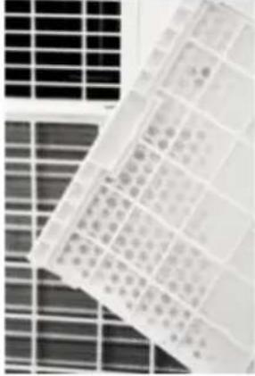 | 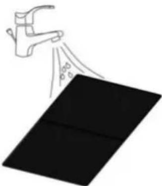 |
| Fig. 1. Switch off the unit and remove the two air filters. | Fig. 2. Rinse the air filter under running water |
Warning!
The surface of the evaporator must not be touched with bare hands, as this can result in damage to the slats and injury.
6. DECOMMISSIONING
6.1 STORAGE
Long-term storage – If the unit will not be used for an extended period of time, it is advisable that it be cleaned and dried completely. Store the unit according to the following steps:
- Remove the plug from the socket. Remove the exhaust hose and the window spare part stored with the unit.
- Drain the remaining water from the unit.
- Clean the filter and let it dry completely.
- Replace the filter
- The unit must stand upright during storage.
- Store the machine in a ventilated, dry, non-corrosive environment and in a safe place indoors.
ATTENTION:
The evaporator inside the system must be dried before packing to avoid damage to components and moulds. Disconnect the unit from the mains and place it in a dry, open location for several days to dry. Another way of drying the system is to switch the machine on, set it to a low-wind ventilation mode and maintain this condition until the drainpipe becomes dry to keep the inside of the enclosure dry and prevent mould growth.
6.2 TRANSPORT
- Before commissioning, set upright and leave to stand still for MIN. 12 HOURS! This protects the compressor, extends its service life considerably and thus prevents a loss of cooling capacity.
- The air conditioning unit must always be placed on the floor with PARTICULAR CARE! Otherwise, cracks may appear in the base plate and the condensate tray, causing condensate to drip onto the floor.
We DO NOT provide warranty services for damage caused by improper use!
6.3 TROUBLESHOOTING
| Problem | Check | Solution | |
| The unit is not working | Check whether the power connection is properly established | Insert the power cable correctly into the wall socket. | |
| Is the water level indicator lit up? | Empty the drip tray. | ||
| Check the room temperature | The operating temperature is 5 – 35°C. | ||
| The unit is working with limited power | Check to see if the air filter is dirty | Clean the air filter if necessary | |
| Check whether the ventilation duct is blocked | Remove the obstacle | ||
| Check whether the room door or window is open | Keep doors and windows closed | ||
| Check that the desired operating mode is selected and that the temperature is set correctly. | Set the mode and temperature to the correct setpoint according to the manual. | ||
| The exhaust hose has been disconnected | Ensure that the exhaust hose is securely attached. | ||
| Water leakage | An overflow may occur when moving the system. | Empty the water tank before transport | |
| Check to see if the drain hose is kinked or bent. | Straighten the hose. | ||
| Excessive noise exposure | Check whether the system is installed correctly | Place the unit on a horizontal and solid surface | |
| Check whether there are any loose, vibrating parts | Secure and attach the parts | ||
| The noises sound like running water | Noise is caused by flowing refrigerant. It's normal. | ||
| Error codes | E0 | Transmission error between main PCB and display PCB. | Check or replace the connection (to be done by specialist staff only) |
| E1 | Defects in the sensor for room temperature | Clean or replace the temperature sensor (to be done by specialist staff only) | |
| E2 | Coil temperature sensor faults | Check or replace the connection. Clean or replace the temperature sensor (to be done by specialist staff only) | |
| Ft | High condensate level warning | Empty the drip tray by removing the rubber plug. | |
- TECHNICAL DATA
| Model | MZKA780 | MZKA1000 |
| Cooling capacity | 2.1 kW | 2.6 kW |
| Dehumidification performance | 19.2 l / 24 h | 24 l / 24 h |
| Operating temperature | 16–32 | 16–32 |
| Temperature adjustment range | 16–32 | 16–32 |
| Max. air volume flow | 360 m^3 /h | 360 m^3 /h |
| Mains connection | 220–240 V/50 Hz | 220–240 V/50 Hz |
| Rated current | 3.5 A | 4.5 A |
| Cooling mode power consumption | 780 | 1,003 |
| Heating power consumption | x | 834 |
| Sound pressure level (max.) | ≤ 65 dB(A) | ≤ 65 dB(A) |
| Refrigerant | R290 | R290 |
| Max. refrigerant filling quantity | 140 | 180 |
| Dimensions (L x W x H) | 34 x 35.4 x 70 | 34 x 35.4 x 70 |
| Weight | 20.5 | 24 |
| Remote control batteries | 2 x AAA | 2 x AAA |
| Min. room size | >7m2 | >9m2 |
8.1 Checking the surrounding area
Before starting any work on systems containing flammable refrigerants, safety tests must be carried out to ensure that the risk of fire is kept to a minimum. When carrying out repairs to the refrigeration system, the following precautions must be observed before carrying out work on the system.
8.2 Work sequence
The work shall be carried out in a controlled manner to minimise the risk of the presence of flammable gases or other vapours while the work is being performed.
8.3 General work area
All maintenance personnel and other individuals working in the local area must be instructed in the sequence of the tasks performed. Avoid working in confined spaces. The working area must be cordoned off. It must be ensured that the working conditions within this area have been safeguarded by checking flammable materials.
8.4 Testing for the presence of refrigerant
Before and during work, the area must be checked with a suitable refrigerant detector to ensure that the technician is aware of the area's potentially flammable nature. Ensure that the leak detection equipment used is suitable for the use of flammable refrigerants, i.e. that it does not spark, is properly sealed and is safe to operate.
8.5 Availability of a fire extinguisher
Suitable fire extinguishers must be available if hot work is to be carried out on the cooling system or associated parts. Provide a dry powder or CO_2 fire extinguisher next to the loading area.
8.6 No ignition source
Nobody carrying out work in connection with a cooling system that pipes containing or having contained a flammable refrigerant are exposed in shall use ignition sources in such a way that they may cause a fire or explosion hazard. All possible ignition sources, including cigarette smoke, must be kept a sufficient distance away from the place of installation, repair, removal and disposal, with the possibility of releasing potentially flammable refrigerant into the surrounding space. Before carrying out the work, the area around the unit must be inspected to ensure that there is no risk of fire or ignition. 'No smoking' signs must be put up.
8.7 Ventilated room
Ensure that the area in question is outdoors or is sufficiently ventilated before entering the system or carrying out hot work. Sufficient ventilation must be ensured during work. Ventilation must distribute the released refrigerant safely and preferably guide it out into the outdoors.
8.8 Testing the unit
If electrical parts are to be replaced, they must comply with the intended use and the correct specification. The manufacturer's maintenance and servicing guidelines must be followed at all times. If in doubt, contact the manufacturer's technical department.
The following tests must be carried out for systems with flammable refrigerants:
- The filling amount corresponds to the room size that the parts containing the refrigerant are installed in;
- The machines and ventilation openings are working properly and are not blocked;
- If an indirect refrigerant circuit is used, check that refrigerant is present in the secondary circuit;
- The markings on the units remain visible and legible. Illegible markings and signs must be replaced;
- The refrigerant pipes or components are installed so that they are highly unlikely to be exposed to any substance that could corrode components containing refrigerant, unless they are made of corrosion-resistant materials or are adequately protected against corrosion.
8.9 Electronic verification
The repair and maintenance of electrical parts requires initial safety tests and procedures for checking the parts. If there is a defect that could jeopardise safety, no power supply may be connected to the circuit until the defect has been sufficiently remedied. A temporary solution must be found if the error cannot be rectified immediately and it is still necessary to continue operation. The system's owner must be informed of this so that all parties involved are instructed accordingly. The initial safety checks include:
- Discharging the condensers: This must be done safely to avoid the risk of sparking;
- Ensuring that no electrical components or lines are live when charging, restoring or flushing the system;
- Ensuring that a continuous earth connection exists.

WARNING!
The system must be installed in rooms that meet the specified room size; see the technical data regarding this matter.
The The system may not be installed in a place where flammable gas could escape.

NOTE!
The manufacturer may provide other suitable examples or additional information about what the refrigerant smells like.

9. DISPOSAL
At the end of your item's long service life, please dispose of the valuable raw materials properly so that proper recycling can take place. If you are not sure how best to proceed, the local waste disposal companies or recycling centres will be happy to help.

WARNING
Releasing refrigerant into the atmosphere is strictly prohibited!
CORRECT DISPOSAL OF THIS PRODUCT
Never dispose of electronic devices in the household waste! Take defective or discarded devices to recycling centers.
Within the EU, this symbol indicates that this product must not be disposed of with household waste. Discarded devices contain valuable recyclable materials that should be recycled and not be disposed of in an uncontrolled manner that could harm the environment or human health. Therefore, please dispose of old devices via appropriate collection systems or send the device to the place where you purchased it for disposal. The latter will then send the device for recycling.
BATTERIES
As end user you are legally obliged to return used batteries. You can return batteries after use to us or to the designated collection points (e.g. municipal collection points or retail outlets) free of charge
You can also return the batteries to us. We will refund the return costs for the old battery.
The symbols shown on the batteries have the following meaning:
= Battery must not be disposed of in the household waste
Pb = Battery contains more than 0.004 mass percent lead
Cd = battery contains more than 0,002 % cadmium by mass
Hg = battery contains more than 0.0005 mass percent of mercury.
NOTICE
Chère cliente, cher client,
EN Appliance shall be installed, operated and stored in a room with floor area larger than 8 m².
3.1 ILLUSTRATION DU PRODUIT
natural_image
Illustration of five different home appliances and a remote control device, labeled 1 to 5 (no text or symbols on the devices themselves)3.4 CHOIX DE L'EMPLACEMENT
natural_image
Technical line drawing of a cylindrical mechanical component with concentric grooves (no text or symbols)natural_image
Three vertical metal bars with cross markings, one upright and one tilted (no text or symbols)natural_image
Simple line drawing of a window with an arrow indicating direction, no text or symbols presentnatural_image
Illustration of a portable air conditioner unit with a cylindrical tube and grid-patterned panel (no text or symbols)natural_image
Illustration of a portable air conditioner unit with a window view (no text or symbols)natural_image
Close-up of a mechanical component with a knob and lever mechanism (no visible text or symbols)natural_image
Close-up of a black mechanical component with a cylindrical protrusion and mounting holes (no visible text or symbols)ÉLIMINATION CORRECTE DE CE PRODUIT
EN Appliance shall be installed, operated and stored in a room with floor area larger than 8 m².
natural_image
Technical line drawing of a coiled pipe or duct assembly (no text or symbols)natural_image
Three vertical metallic bars with cutouts, one upright and one angled (no text or symbols)natural_image
Simple line drawing of a window with an arrow pointing to the left pan, no text or symbols present.natural_image
Illustration of a portable air conditioner unit with cooling fins and ventilation slots (no text or symbols)natural_image
Illustration of a portable air conditioner unit with a window view (no text or symbols)natural_image
Two-panel image showing a solar panel array and a spray gun spraying over a black rectangular object (no text or symbols)www.deubaservice.de
SERVICEPORTAL
DE
For any kind of service, complaints and technical support, you can confidently turn to our trained staff.
FR
66663 Merzig, Germany
DEUBA XXL
Copyright by

Stand 2020/12 Rev1