
Fan 1500 DH - Fan BOSCH - Free user manual and instructions
Find the device manual for free Fan 1500 DH BOSCH in PDF.
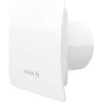


| Product type | Air extractor (bathroom fan) |
| Brand | Bosch |
| Model | Fan 1500 DH |
| Maximum air flow (125 mm model) | 182 m³/h |
| Electrical power consumption (125 mm model) | 18 W |
| Sound power level (125 mm model) | 59 dB(A) |
| Supply voltage | 230 V ~ 50 Hz |
| Protection rating | IP24 |
| Protection class | II (double insulation) |
| Duct diameter | 100 mm or 125 mm depending on version |
| Integrated humidity sensor (hygrostat) | Yes, adjustable from 40% to 90% RH |
| Timer (delayed shut-off) | 3 to 30 minutes, adjustable via potentiometer |
| Control type | Automatic (hygrostat) and manual (separate switch) |
| Maximum ambient temperature | 40 °C |
| Storage temperature | -20 °C to +40 °C |
| Maintenance | Clean with a damp cloth; do not use solvents or water jet |
| Technical check frequency | Every 6 months (check rotor) |
| Bearing lifespan | ≥ 30,000 hours at maximum ambient temperature |
| Installation | Wall-mounted only, at least 2.3 m from the floor (fixing with dowels) |
| Intended use | Extraction of normal or slightly dusty air (<10 µm) in temperate climate |
| Approval | Compliant with standard EN 60335-1 (safety of household appliances) |
| After-sales service | elm.leblanc S.A.S., tel. 0 820 00 6000 (€0.12/min + call price) |
Frequently Asked Questions - Fan 1500 DH BOSCH
User questions about Fan 1500 DH BOSCH
0 question about this device. Answer the ones you know or ask your own.
Ask a new question about this device
Download the instructions for your Fan in PDF format for free! Find your manual Fan 1500 DH - BOSCH and take your electronic device back in hand. On this page are published all the documents necessary for the use of your device. Fan 1500 DH by BOSCH.
USER MANUAL Fan 1500 DH BOSCH
DE - Bedienungsanleitung für den Badventilator 2 EN - Bathroom extractor fan instructions manual. 10 IT - Istruzioni per l'uso dell'aspiratore da bagno....17 FR - Notice d'installation de l'extracteur de salle de bains. 24 TR - Banyo Aspiratörü Kullanım Kılavuzu 32 ES - Manual de instrucciones del extractor de baño 40 PT - Manual de instruções do extrator da casa de banho 47 NL - Installatie- en bedieningshandleiding voor badkamerafzuigventilator . . . . . . . . . 55 SE - Bruksanvisning för badrumsfläkt 63 PL - Instrukcja obsługi łazienkowego wentylatora wyciągowego. 70
The following safety symbols show important safety information. Follow all safety regulations and the safety symbols shown in the Instructions manual to avoid injury and hazards!

Danger!
Electrocution hazard: high voltage!
Attention: rotating parts!
2 GENERAL SAFETY PRINCIPLES:
Information for the target group
Observe the instructions in the manual. Failure to follow the instructions may result in property damage, personal injury or even death.
- Read the installation instructions before proceeding with the installation.
- Read and retain this manual before using the device.
- Observe safety principles and warnings.
- Observe national and regional regulations, technical rules and guidelines.
Safety of household and similar electrical appliances
In order to avoid hazards posed by electrical appliances, the following requirements apply in accordance with the EN 60335-1 standard:
- "This product can be used by children at least 8 years old, by people with impaired physical and/or mental abilities, and by people without any experience in or understanding of the operation of the product, if supervised or instructed by a competent adult in the safe use of the product so that they understand the relevant operating risks."
- "Children should not play with the appliance. Children should not be allowed to clean or maintain the product without adult supervision."
- "If the power cord is defective, it must be replaced by the manufacturer, its service department, or a similarly qualified person to avoid hazards."
Risk of fatal injury from electric shock!
Touching live electrical parts may result in electric shock.
- The bathroom extractor fan is designed for permanent indoor connection, for fixed electrical installation, which must be equipped with means/devices for total contact breakage to ensure complete separation under overvoltage conditions of category III according to the regulations for such installation.
- The bathroom extractor fan is designed for installation at a substantial height, i.e., 2.3 m above the floor. Installation - only in accordance with the descriptions and guidelines in this manual, in particular with regard to the required installation position, by inserting the power cord into the housing.
- Measures shall be taken to prevent gases from escaping from open smoke ducts or other open flame equipment into the room.
- Unauthorized changes or modifications to the equipment are not permitted.
- Before installing the equipment, check the load-bearing capacity of the structure to which it is to be mounted, as improper mounting can lead to damage or destruction of the equipment and can pose a risk to persons in the vicinity of the equipment in the following situations.

The appliance may become dangerous if used improperly or if installed by unqualified personnel.
3 APPLICATION AND OPERATING CONDITIONS
- Bathroom extractor fans are designed to transport normal or slightly dusty air (particle size < 10µm ) of low aggressiveness and humidity in temperate climates according to and within their limits of performance.
- The appliance is designed only for continuous operation in a building if there is no access to the power supply line.
- The maximum temperature of the medium handled by the bathroom extractor fan and the maximum ambient temperature are +40°C.
- The exhaust fan is IP4 and protection class II device if it is installed in accordance with Appendix 1 (Fig. 5) in the wall. The fan is not designed for ceiling installation.
- The bathroom extractor fan must be operated according to its intended use and in accordance with the data provided on the rating plate.
- The bathroom extractor fan must be connected to the building mains (recessed electrical installation) with one of the following power cables: NYM-O 2x1.5 mm², NYM-O 3x1.5 mm², NYM-J 3x1.5 mm², depending on the fan version - see point 6. If a cable with more wires has to be used, e.g., NYM-J 4x1.5 mm², the outer diameter of the cable must not exceed 14 mm.
- The bathroom extractor fan cannot be used to circulate air with the following characteristics: - viscous contaminants prone to deposition in the bathroom extractor fan, - corrosive contaminants which may degrade the bathroom extractor fan,
- contaminants from mixtures of flammable substances in the form of gases, vapours, mists and dusts, which in combination with air can create an explosive atmosphere.
- Motors fitted with ball bearings are designed for a service life of at least 30,000 hours at maximum permissible ambient temperature so as to enable continuous operation at maximum efficiency.
- If the user has used an additional controller in the appliance, the controller cannot cause extreme operation of the appliance during frequent switching on and off. • The device is not suitable for use above 2000 m.
4 TRANSPORT AND STORAGE
- Bathroom extractor fans should be stored in their original packaging in a dry place protected from weather conditions.
- Maintain storage and transport temperatures between -20°C and +40°C.
- Avoid shocks and impacts. Bathroom extractor fans should be transported in their original packaging.
- If the storage period is longer than 1 year, it is necessary to check the correct functioning of the motor bearings by manually turning the rotor before installation.
- Disposal must be carried out properly, in an environmentally sound and legal manner.
- Damage caused by improper transport, storage or start-up must be demonstrated and is not covered by the warranty.
5 PRODUCT DATA
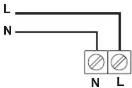
Terminal block (standard version, no part index suffix). Models with terminal block should be connected according to the wiring diagram in Fig. 2.
The bathroom extractor fan is operated by means of a separate switch, which is part of the building electrical installation (not part of the appliance).
Humidity sensor and timer (part name suffix "DH"). Models equipped with humidity sensor (hygrostat) and stop delay (timer) should be connected according to the wiring diagram in Fig. 3 or 4.
The operation of the bathroom extractor fan will depend on the power supply connection method. When connected as shown in Fig. 4, the bathroom extractor fan starts automatically when the air humidity exceeds the set value. It is switched off when the humidity drops below the set value and after the time of the set stop delay has elapsed since the humidity drops.
If connected according to Fig. 3, in addition to automatic operation, it is possible to manually start the bathroom extractor fan by means of a light switch or a separate switch for the bathroom extractor fan. If the light or the bathroom extractor fan is off, as in the first case, the appliance will stop after the stop delay time set with the potentiometer has elapsed, provided that the humidity level in the room is below the level preset on the potentiometer. The humidity detection system is the master system. The humidity sensor operating range is 40% to 90% of relative air humidity. The system is additionally equipped with a timer.
The stop delay time can be set with a potentiometer knob on the electronic module of the stop delay timer. The minimum stop delay time is 3 minutes with the potentiometer knob rotated counterclockwise. Turn the potentiometer knob clockwise to set a longer stop delay time accordingly. The maximum stop delay time is 30 minutes. The stop delay time regulation is smooth regulation. The fan stop delay time is counted from the time of switching off the light or a separate switch to which the appliance is
connected or from the time of humidity drop set on the humidity sensor potentiometer.
ATTENTION: When the green diode located in the electronic system is on, it means that the humidity level in the room is higher than the preset on the potentiometer controlling the humidity level adjustment. As long as the diode is on, the fan will not start counting down the stop delay after which the fan is switched off. It will take place only after the humidity level in the room drops and the green diode goes off.
6 INSTALLATION

The bathroom extractor fan should only be installed, connected to electrical mains and commissioned for use by qualified personnel in accordance with applicable laws!
Necessary tools:
Cross-tip screwdriver Drill-driver

Installation procedure
• Determine the installation location of the fan. - Prepare the power cable. Use NYM-O 2x1,5 mm 2 or NYM-O 3x1,5 mm 2 depending on the equipment variant. If NYM-J 3x1,5 mm 2 or NYM-J 4x1,5 mm 2 cable is used in the installation, insulate the earth cable.
NOTE: Ensure that the power cable is not live before proceeding.
- Remove the push-fit hole plugs (9) using a pointed tool.
- Measure and drill the holes for the fan, the Ø6 mm fixing pins (included in the package), and then route the power cable as shown in Figure 5.
- Remove the electrical cover (2) secured with screws (3). Pass the double-insulated electrical cable through the passage (4). The cable should be led in a length that allows connection to the power terminals.
Before fixing the fan: Remove foreign objects from inside the fan; check that the rotor rotates freely by setting it in motion with your hand; ensure there is enough space for the opening of the check valve shutter located at the fan outlet.
It is recommended to connect the exhaust fan to the duct installation using flexible tubes.
- Place the fan body (5) and the mounting pins into the prepared holes.
- Secure the fan to the partition by screwing the screws into the fixing plugs, using the mounting holes (6).
- Insert the mounting hole plugs.
- Remove the outer insulation from the cable, remove the wire insulation to a length of 4 mm.
- Arrange the cable and connect it according to the connection diagram appropriate for the model being installed.
- Ensure that the cable conductors are securely attached to the terminals.
- Check the fan for secure mounting and proper electrical installation.
- Adjust the parameters:
Applies to the DH version: Set the time delay value and humidity sensor sensitivity using the key (7) on the potentiometers located on the controller (8).
Check the sealing of the connection cable.
-The connection cable must be protected in such a way that, in the event of flooding, under no circumstances can water reach the live parts.
- Put on the electrical cover (2) and then screw it in with screws (3).
- Attach the front panel (1) which acts as protection against touching moving parts.
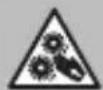
ATTENTION! Hazard of crushing fingers with the rotating fan rotor! Install the guard against the direct touch of moving parts before starting!
7 FIRST START OF THE DEVICE
The first start may only take place after all safety precautions have been checked and risks have been eliminated. After the bathroom extractor fan start-up, check that it runs steadily and the air is handled efficiently (out of the room and through the exhaust duct to the outside).
The bathroom extractor fan may only be used with the front panel, which provides protection against contact with moving parts.
The installer is responsible for compliance with the applicable standards and may be held liable for accidents resulting from the absence of safety devices.
8 ELECTRICAL CONNECTIONS
- The electrical connection and start-up may only be carried out by qualified personnel who are qualified to perform electrical work. • Always follow the applicable standards, safety regulations and technical requirements specified by the power company!
- The type of mains system, voltage and frequency must match the data on the rating plate of the bathroom extractor fan.
- For bathroom extractor fans with stop delay time, the minimum voltage at the T terminal that starts the stop delay countdown or starts the exhaust fan is 130V AC.
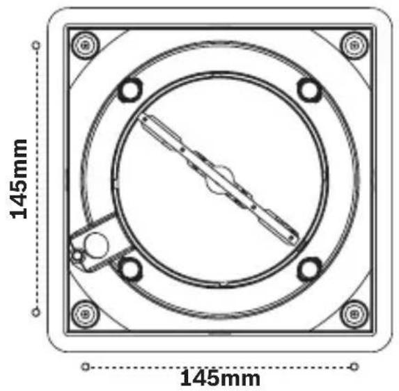
9 DIMENSIONS
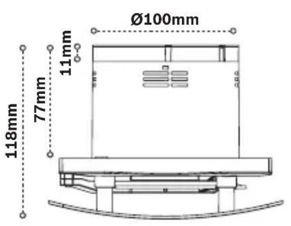
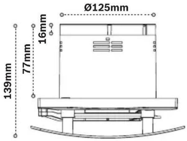
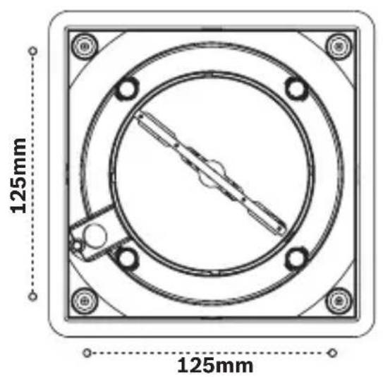
The dimensions of the models are listed on the packaging and Figure 6
10 MAINTENANCE AND CLEANING
Maintenance
- Observe the safety and OHS regulations during all maintenance work.
- Before servicing the bathroom extractor fan, disconnect it from the mains and secure it against inadvertent operation!
- The bathroom extractor fan ventilation ducts must be clear of foreign bodies: hazard of injury by objects blown out at a high speed!
- Do not attempt any maintenance works when the fan is running.
- If excessive vibrations are felt or heard, have the product maintenance carried out by a qualified electrician.
- Depending on the degree of impeller contamination, technical inspections must be carried out at least once every 6 months!
- Check the rotor for cracks.
- The manufacturer is not liable for damage caused by improper repair.
- In the case of appliances with ball bearing motors with "lifetime lubrication", the motor does not require lubrication.
11 CLEANING
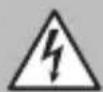
Electrocution risk by damaged wiring insulation! Before cleaning, completely disconnect the bathroom extractor fan from the mains and secure it against inadvertent operation!
- Clean the front cover and visible parts of the housing with a damp cloth.
- Do not use any aggressive solvents!
- Do not clean with a high pressure cleaner or strong jets of water!
- When cleaning, make sure that no water enters the electric motor or terminal box. The grille at the bathroom fan inlet must always be kept clean.
12 Waste electrical and electronic equipment
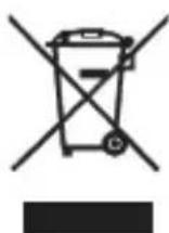
This symbol means that the product may not be disposed of together with other waste, but must be taken to a collection point for treatment, collection, recycling and disposal.
This symbol refers to countries where electronic scrap legislation is in force, e.g. the "European Directive 2012/19/EC on waste electrical and electronic equipment". These rules establish a framework for the return and recycling of waste electronic equipment in each country.
Since electronic equipment may contain hazardous substances, it must be recycled in a responsible manner so that potential damage to the environment and risks to human health are minimised. In addition, the recycling of electronic scrap contributes to the protection of natural resources.
Since electronic equipment may contain hazardous substances, it must be recycled in a responsible manner so that potential damage to the environment and risks to human health are minimized. In addition, the recycling of electronic scrap contributes to the protection of natural resources.
For further information on how to dispose of waste electrical and electronic equipment in an environmentally sound manner, please contact your local authority, the waste disposal company, or the retailer from whom you purchased the product.
Find more information here: http://www.weee.bosch-thermotechnology.com/
1 WARNING:
| a | Supplier's name | Bosch Thermotechnik GmbH | Bosch Thermotechnik GmbH | |||||
| b | Supplier model identifier (code) | F1500 W 100 | F1500 W 125 | |||||
| c | Specific energy consumption SEC class - climate zone | kWh /(m2·a) | cold | temperate | warm | cold | temperate | warm |
| -22,4 | -9,1 | -1,4 | -29,3 | -10,5 | -2,9 | |||
| d | Typology | UVR unidirectional | UVR unidirectional | |||||
| e | Type of drive installed / intended to be installed | single speed | single speed | |||||
| f | Type of heat recovery system | none | none | |||||
| g | Thermal efficiency of heat recover | % | - | - | ||||
| h | Maximum flow rate | m3/h | 95 | 182 | ||||
| i | Electric power input of the fan drive | W | 13,5 | 18 | ||||
| j | Sound power level | dB(A) | 54 (ISO 3744) | 59 (ISO 3744) | ||||
| k | Reference flow rate | m3/s | 0,0264 | 0,0505 | ||||
| l | Reference pressure difference | Pa | 0 | 0 | ||||
| m | Specific power input | W/(m3/h) | 0,1421 | 0,0995 | ||||
| n | Control factor and control typology | 1 | 1 | |||||
| o | Max. internal leakage rate / max. external leakage rate | % | - | - | ||||
| p | Mixing rate | % | - | - | ||||
| q | Position and description of visual filter warning | % | - | - | ||||
| r | Instructions to install regulated supply/exhaust | see instruction sheet | see instruction sheet | |||||
| s | Internet address for disassembly instructions | www.bosch-thermotechnology.com | www.bosch-thermotechnology.com | |||||
| t | Airflow sensitivity to pressure variations at -20 Pa / +20 Pa | - | - | |||||
| u | Indoor / outdoor air tightness | m3/h | - | - | ||||
| a | Supplier's name | Bosch Thermotechnik GmbH | Bosch Thermotechnik GmbH | |||||
| b | Supplier model identifier (code) | F1500 DH W 100 | F1500 DH W 125 | |||||
| c | Specific energy consumption SEC class - climate zone | kWh /(m2·a) | cold | temperate | warm | cold | temperate | warm |
| -33,4 | -15,1 | -4,5 | -34,7 | -16,3 | -5,8 | |||
| d | Typology | UVR unidirectional | UVR unidirectional | |||||
| e | Type of drive installed / intended to be installed | single speed | single speed | |||||
| f | Type of heat recovery system | none | none | |||||
| g | Thermal efficiency of heat recover | % | - | - | ||||
| h | Maximum flow rate | m3/h | 95 | 182 | ||||
| i | Electric power input of the fan drive | W | 13,5 | 18 | ||||
| j | Sound power level | dB(A) | 54 (ISO 3744) | 59 (ISO 3744) | ||||
| k | Reference flow rate | m3/s | 0,0264 | 0,0505 | ||||
| l | Reference pressure difference | Pa | 0 | 0 | ||||
| m | Specific power input | W/(m3/h) | 0,1421 | 0,0995 | ||||
| n | Control factor and control typology | 0,85 | 0,85 | |||||
| o | Max. internal leakage rate / max. external leakage rate | % | - | - | ||||
| p | Mixing rate | % | - | - | ||||
| q | Position and description of visual filter warning | % | - | - | ||||
| r | Instructions to install regulated supply/exhaust | see instruction sheet | see instruction sheet | |||||
| s | Internet address for disassembly instructions | www.bosch-thermotechnology.com | www.bosch-thermotechnology.com | |||||
| t | Airflow sensitivity to pressure variations at -20 Pa / +20 Pa | - | - | |||||
| u | Indoor / outdoor air tightness | m3/h | - | - | ||||
The first start may only take place after all safety precautions have been checked and risks have been eliminated. After the bathroom extractor fan start-up, check that it runs steadily and the air is handled efficiently (out of the room and through the exhaust duct to the outside).
The first start may only take place after all safety precautions have been checked and risks have been eliminated. After the bathroom extractor fan start-up, check that it runs steadily and the air is handled efficiently (out of the room and through the exhaust duct to the outside).
The bathroom extractor fan may only be used with the front panel, which provides protection against contact with moving parts.
The installer is responsible for compliance with the applicable standards and may be held liable for accidents resulting from the absence of safety devices.
4 TRANSPORT AND STORAGE
- The fan is designed for moving normal or slightly dusty air with low activity and humidity (particle size <10 μm-8g) in moderate climates, in accordance with its specifications.
- The device is designed for continuous operation only, unless otherwise specified on the electrical connection line.
- The fan is an IPX4 protection rating and class II protection device, if installed in accordance with Annex 1 (Fig. 5). The fan is not intended for use in wet areas.
- The device is not suitable for use with 2000đ flavor.
Image/Figure/Fig/Rys. 4
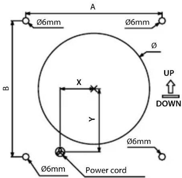
| Model | ∅ | A B X Y | ||
| F1500W100F1500 DH W 100 | 102 mm 1 | 25 mm 125 mm 31 mm | 58 mm | |
| F1500W125F1500 DH W 125 | 127 mm 1 | 45 mm 145 mm 32 mm | 61 mm |
Image/Figure/Fig/Rys. 6
F1500 W 100; F1500 DH W 100 F1500 W 125; F1500 DH W 125
Germany (DE)

- GENERAL SAFETY PRINCIPLES
- INFORMATION FOR THE TARGET GROUP
- SAFETY OF HOUSEHOLD AND SIMILAR ELECTRICAL APPLIANCES
- RISK OF FATAL INJURY FROM ELECTRIC SHOCK
- APPLICATION AND OPERATING CONDITIONS
- TRANSPORT AND STORAGE
- PRODUCT DATA
- INSTALLATION
- NECESSARY TOOLS
- CROSS-TIP SCREWDRIVER DRILL-DRIVER
- INSTALLATION PROCEDURE
- NOTE: ENSURE THAT THE POWER CABLE IS NOT LIVE BEFORE PROCEEDING
- FIRST START OF THE DEVICE
- ELECTRICAL CONNECTIONS
- DIMENSIONS
- MAINTENANCE AND CLEANING
- MAINTENANCE
- CLEANING
- WASTE ELECTRICAL AND ELECTRONIC EQUIPMENT
- THE FIRST START MAY ONLY TAKE PLACE AFTER ALL SAFETY PRECAUTIONS HAVE BEEN CHECKED AND RISKS HAVE BEEN ELIMINATED. AFTER THE BATHROOM EXTRACTOR FAN START-UP, CHECK THAT IT RUNS STEADILY AND THE AIR IS HANDLED EFFICIENTLY (OUT OF THE ROOM AND THROUGH THE EXHAUST DUCT TO THE OUTSIDE)
- GERMANY (DE)
Brand : BOSCH
Model : Fan 1500 DH
Category : Fan