
X99E-ITX/ac - Motherboard ASROCK - Free user manual and instructions
Find the device manual for free X99E-ITX/ac ASROCK in PDF.

| Product Type | Mini-ITX Motherboard |
| Dimensions | 17 cm x 17 cm (Mini-ITX form factor) |
| Compatible Processor | Intel Core i7 / Xeon, LGA 2011-3 socket |
| Chipset | Intel X99 |
| Memory | 2 x DDR4 DIMM, up to 256 GB (Xeon), supports ECC and non-ECC |
| Expansion Slots | 1 x PCIe 3.0 x16, 1 x half-mini-PCIe (WiFi) |
| Audio | Realtek ALC1150 7.1-channel HD, TI NE5532 headphone amplifier |
| Network | 2 x Gigabit LAN (Intel I218V + I211AT), teaming support |
| Wireless | Wi-Fi 802.11ac dual-band (2.4/5 GHz), Bluetooth 4.0 |
| Storage | 6 x SATA3 6 Gb/s, 1 x SATA Express, 1 x Ultra M.2 PCIe Gen3 x4 |
| Rear Panel | 1x PS/2, 1x eSATA, 2x USB 3.1 Type A, 4x USB 3.0, 2x RJ45, SPDIF optical output, HD audio, Clear CMOS button |
| Internal Connectors | 1x USB 3.0 header, 1x USB 2.0 header, audio headers, TPM, chassis intrusion, LED, fans |
| Power Supply | ATX 24-pin + 12V 8-pin |
| BIOS | AMI UEFI with multilingual graphical interface |
| Operating System | Windows 10/8.1/8/7 (64/32-bit) |
| Special Features | Digi Power, Nichicon capacitors, overvoltage protection, 15μ gold-plated contacts |
| Maintenance and Cleaning | Regular dusting with compressed air, avoid solvents |
| Security | Lightning/ESD protection, optional TPM module, chassis intrusion detection |
| Spare Parts and Repairability | Replaceable CR2032 CMOS battery, standard connectors |
| Package Contents | Motherboard, manual, CD, I/O panel, SATA cables, CPU fan, watercooling plate, WiFi module, antennas, screws |
Frequently Asked Questions - X99E-ITX/ac ASROCK
User questions about X99E-ITX/ac ASROCK
0 question about this device. Answer the ones you know or ask your own.
Ask a new question about this device
Download the instructions for your Motherboard in PDF format for free! Find your manual X99E-ITX/ac - ASROCK and take your electronic device back in hand. On this page are published all the documents necessary for the use of your device. X99E-ITX/ac by ASROCK.
USER MANUAL X99E-ITX/ac ASROCK
Published March 2015
Copyright©2015 ASRock INC. All rights reserved.
Copyright Notice:
No part of this documentation may be reproduced, transcribed, transmitted, or translated in any language, in any form or by any means, except duplication of documentation by the purchaser for backup purpose, without written consent of ASRock Inc.
Products and corporate names appearing in this documentation may or may not be registered trademarks or copyrights of their respective companies, and are used only for identification or explanation and to the owners' benefit, without intent to infringe.
Disclaimer:
Specifications and information contained in this documentation are furnished for informational use only and subject to change without notice, and should not be constructed as a commitment by ASRock. ASRock assumes no responsibility for any errors or omissions that may appear in this documentation.
With respect to the contents of this documentation, ASRock does not provide warranty of any kind, either expressed or implied, including but not limited to the implied warranties or conditions of merchantability or fitness for a particular purpose.
In no event shall ASRock, its directors, officers, employees, or agents be liable for any indirect, special, incidental, or consequential damages (including damages for loss of profits, loss of business, loss of data, interruption of business and the like), even if ASRock has been advised of the possibility of such damages arising from any defect or error in the documentation or product.

This device complies with Part 15 of the FCC Rules. Operation is subject to the following two conditions:
(1) this device may not cause harmful interference, and
(2) this device must accept any interference received, including interference that may cause undesired operation.
CALIFORNIA, USA ONLY
The Lithium battery adopted on this motherboard contains Perchlorate, a toxic substance controlled in Perchlorate Best Management Practices (BMP) regulations passed by the California Legislature. When you discard the Lithium battery in California, USA, please follow the related regulations in advance.
"Perchlorate Material-special handling may apply, see www.dtsc.ca.gov/hazardouswaste/perchlorate"
ASRock Website: http://www.asrock.com

Manufactured under license under U.S. Patent Nos: 5,956,674; 5,974,380; 6,487,535; 7,003,467 & other U.S. and worldwide patents issued & pending. DTS, the Symbol, & DTS and the Symbol together is a registered trademark & DTS Connect, DTS Interactive, DTS Neo:PC are trademarks of DTS, Inc. Product includes software.
© DTS, Inc., All Rights Reserved.

Connect

Interactive

Neo:PC
Motherboard Layout
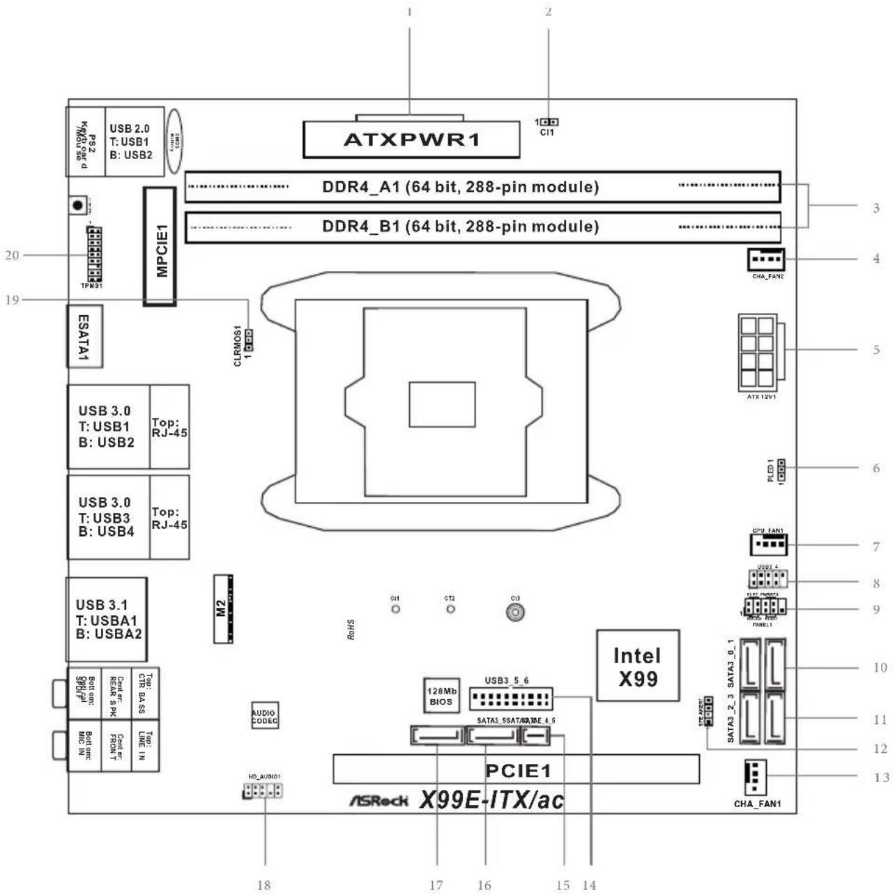
text_image
ATXPWR1 DDR4_A1 (64 bit, 288-pin module) DDR4_B1 (64 bit, 288-pin module) MPCIe1 TPW31 ESATA1 USB 3.0 T: USB1 B: USB2 Top: RJ-45 USB 3.0 T: USB3 B: USB4 Top: RJ-45 USB 3.1 T: USBA1 B: USBA2 M2 RelS O1 O2 O3 Intel X99 128Mb BIOS SATA3_5SAT8AXME_4.5 AUDIO CODEC PCIE1 ASRock X99E-ITX/ac CHA_FAN1 CHA_FAN2 ATX 12V1 PLED 1 CPU FAN1 USB1.4 USSA MONTEC 128MB BIOS SATA3_2_3 SATA3_0_1 CHA_FAN1No. Description
1 ATX Power Connector (ATXPWR1)
2 Chassis Intrusion Header (CI1)
3 2 x 288-pin DDR4 DIMM Slots (DDR4_A1, DDR4_B1)
4 Chassis Fan Connector (CHA_FAN2)
5 ATX 12V Power Connector (ATX12V1)
6 Power LED Header (PLED1)
7 CPU Fan Connector (CPU_FAN1)
8 USB 2.0 Header (USB3_4)
9 System Panel Header (PANEL1)
10 SATA3 Connectors (SATA3_0_1)
11 SATA3 Connectors (SATA3_2_3)
12 Chassis Speaker Header (SPEAKER1)
13 Chassis Fan Connector (CHA_FAN1)
14 USB 3.0 Header (USB3_5_6)
15 SATA Express Connector (SATAE_4_5)
16 SATA3 Connector (SATA3_5)
17 SATA3 Connector (SATA3_4)
18 Front Panel Audio Header (HD_AUDIO1)
19 Clear CMOS Jumper (CLRCMOS1)
20 TPM Header (TPMS1)
I/O Panel
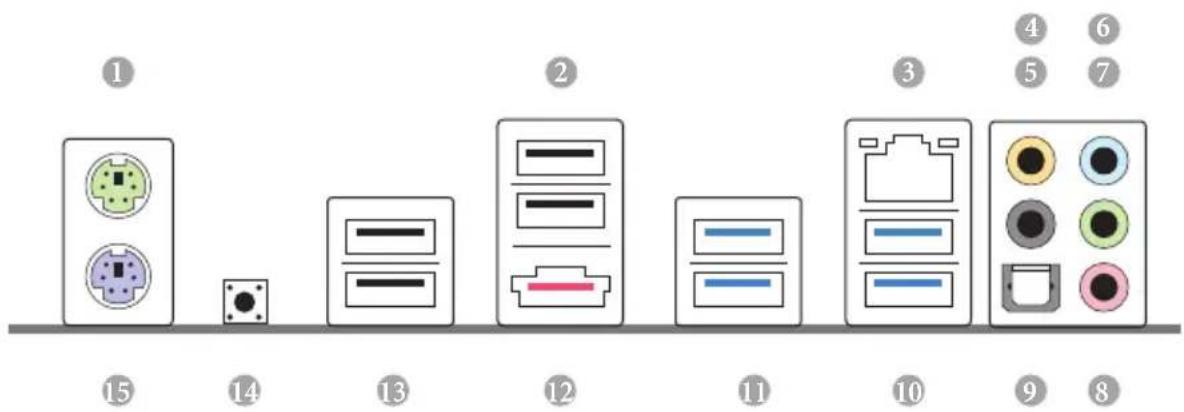
text_image
Diagram showing 15 labeled electronic components with corresponding icons and numbers, likely representing a device or system layout.No. Description No. Description
1 PS/2 Mouse Port 9 Optical SPDIF Out Port
2 USB 2.0 Ports (USB23) 10 USB 3.0 Ports (USB3_23)
3 LAN RJ-45 Port (Intel® I218V)* 11 USB 3.0 Ports (USB3_01)
4 Central / Bass (Orange) 12 eSATA Connector***
5 Rear Speaker (Black) 13 USB 2.0 Ports (USB01)
6 Line In (Light Blue)
14 Clear CMOS Switch
7 Front Speaker (Lime) ^** 15 PS/2 Keyboard Port
8 Microphone (Pink)
* There are two LEDs on each LAN port. Please refer to the table below for the LAN port LED indications.
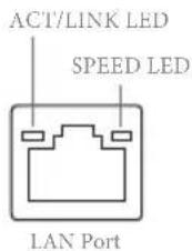
text_image
ACT/LINK LED SPEED LED LAN Port| Activity / Link LED Speed LED | |||
| Status Description Status Description | |||
| Off No Link Off | 10Mbps connection | ||
| Blinking | Data Activity | Orange | 100Mbps connection |
| On Link Green | 1Gbps connection | ||
** If you use a 2-channel speaker, please connect the speaker's plug into "Front Speaker Jack". See the table below for connection details in accordance with the type of speaker you use.
| Audio Output Channels | Front Speaker (No. 7) | Rear Speaker (No. 5) | Central / Bass (No. 4) | Line In (No. 6) |
| 2 V -- -- -- | ||||
| 4 V V -- -- | ||||
| 6 V V V -- | ||||
| 8 V V V V |

To enable Multi-Streaming, you need to connect a front panel audio cable to the front panel audio header. After restarting your computer, you will find the "Mixer" tool on your system. Please select "Mixer ToolBox" click "Enable playback multi-streaming", and click "ok". Choose "2CH", "4CH", "6CH", or "8CH" and then you are allowed to select "Realtek HDA Primary output" to use the Rear Speaker, Central/Bass, and Front Speaker, or select "Realtek HDA Audio 2nd output" to use the front panel audio.
*** The eSATA connector supports SATA with cables within 1 meters. The S_SATA3_3 connector is shared with the eSATA port
Chapter 1 Introduction
Thank you for purchasing ASRock X99E-ITX/ac motherboard, a reliable motherboard produced under ASRock's consistently stringent quality control. It delivers excellent performance with robust design conforming to ASRock's commitment to quality and endurance.

Because the motherboard specifications and the BIOS software might be updated, the content of this documentation will be subject to change without notice. In case any modifications of this documentation occur, the updated version will be available on ASRock's website without further notice. If you require technical support related to this motherboard, please visit our website for specific information about the model you are using. You may find the latest VGA cards and CPU support list on ASRock's website as well. ASRock website http://www.asrock.com.
1.1 Package Contents
• ASRock X99E-ITX/ac Motherboard (Mini-ITX Form Factor)
• ASRock X99E-ITX/ac Quick Installation Guide
• ASRock X99E-ITX/ac Support CD
• 2 x Serial ATA (SATA) Data Cables (Optional)
• 1 x I/O Panel Shield
- 1 x CPU Cooler
* This motherboard supports this free bundled CPU cooler (Dimension: 112.0 x 84.0 x 67.0 mm) or other CPU coolers for Narrow ILM (LGA 2011/LGA2011-v3 platform).
• 1 x Water Cooling Mounting Plate
*This mounting plate is only compatible with selected CPU coolers, such as Cooler Master's Seidon 120V Plus/120V. Please visit our website for the latest updates:
http://www.asrock.com
• 1 x WiFi-802.11ac Module
• 2 x SMA WiFi Antenna Cables
• 1 x ASRock WiFi 2.4/5 GHz Antennas
• 1 x WiFi Module Bracket
• 2 x Screws for WiFi Module
• 1 x Screw for M.2 Socket
• 1 x ASRock U3 to U2 Converter
1.2 Specifications
| Platform | Mini-ITX Form Factor2oz Copper PCB8 Layer PCBHigh Density Glass Fabric PCB |
| CPU | Supports Intel® CoreTM i7 and Xeon® 22-Core ProcessorsFamily for the LGA 2011-3 SocketDigi Power design6 Power Phase designSupports Intel® Turbo Boost 2.0 TechnologySupports Untied Overclocking Technology |
| Chipset | Intel® X99 |
| Memory | Dual Channel DDR4 Memory Technology2 x DDR4 DIMM SlotsSupports DDR4 3200+(OC)*/2933+(OC)/2800(OC)/2400 (OC)/2133 non-ECC, un-buffered memory* Please refer to Memory Support List on ASRock's website for more information. (http://www.asrock.com/)Supports non-ECC RDIMM (Registered DIMM)Supports DDR4 ECC, un-buffered memory/RDIMM with Intel® Xeon® processors E5 series in the LGA 2011-3 SocketMax. capacity of system memory: 128GB (with CoreTM i7 CPU Broadwell-E) or 64GB (with CoreTM i7 CPU Haswell-E) or 256GB (With Xeon® CPU)Supports Intel® Extreme Memory Profile (XMP) 2.015μ Gold Contact in DIMM Slots |
| Expansion Slot | 1 x PCI Express 3.0 x16 Slot (PCIE1: x16 mode)1 x Vertical Half-size Mini-PCI Express Slot: For WiFi + BT Module15μ Gold Contact in VGA PCIe slot (PCIE1) |
| Audio | 7.1 CH HD Audio with Content Protection (Realtek ALC1150 Audio Codec)Premium Blu-ray Audio support |
• Supports Surge Protection (ASRock Full Spike Protection)
- Nichicon Fine Gold Series Audio Caps
- TI® NE5532 Premium Headset Amplifier (Supports up to 600 Ohm headsets)
• Supports DTS Connect
LAN
• Gigabit LAN 10/100/1000 Mb/s
• 1 x Giga PHY Intel ^® I218V, 1 x GigaLAN Intel ^® I211AT
• Supports Intel ^® Remote Wake Technology (on Intel ^® I218V)
• Supports Wake-On-LAN
- Supports Lightning/ESD Protection (ASRock Full Spike Protection)
• Supports Dual LAN with Teaming
• Supports Energy Efficient Ethernet 802.3az
- Supports PXE
Wireless
• Supports IEEE 802.11a/b/g/n/ac
• Supports Dual-Band (2.4/5 GHz)
• Supports high speed wireless connections up to 867Mbps
- 2 antennas to support 2 (Transmit) x 2 (Receive) diversity technology
• Supports Bluetooth 4.0 / 3.0 + High speed class II
Rear Panel
• 1 x PS/2 Mouse/Keyboard Port
• 1 x Optical SPDIF Out Port
• 1 x eSATA Connector
- 2 x USB 2.0 Ports (Supports ESD Protection (ASRock Full Spike Protection))
- 2 x USB 3.1 Type-A Ports (10 Gb/s) (ASMedia ASM1142) (Supports ESD Protection (ASRock Full Spike Protection))
- 4 x USB 3.0 Ports (Intel® X99) (Supports ESD Protection (ASRock Full Spike Protection))
- 2 x RJ-45 LAN Ports with LED (ACT/LINK LED and SPEED LED)
• 1 x Clear CMOS Switch
- HD Audio Jacks: Rear Speaker / Central / Bass / Line in / Front Speaker / Microphone
Storage
- 6 x SATA3 6.0 Gb/s Connectors, support RAID (RAID 0, RAID 1, RAID 5, RAID 10 and Intel Rapid Storage 13), NCQ, AHCI and Hot Plug
* RAID is supported on SATA3_0 \~ SATA3_5 ports only.
- 1 x SATA Express 10 Gb/s Connector (shared with SATA3_4, SATA3_5)
* Support to be announced
• 1 x eSATA Connector, supports NCQ, AHCI and Hot Plug
- 1 x Ultra M.2 Socket, supports M.2 SATA3 6.0 Gb/s module and M.2 PCI Express module up to Gen3 x4 (32 Gb/s)
Connector
• 1 x Chassis Intrusion Header
- 1 x TPM Header
• 1 x Power LED Header
- 1 x CPU Fan Connector (4-pin) (Supports 3-pin/4-pin Smart Fan Speed Control)
- 2 x Chassis Fan Connectors (2 x 4-pin) (Support 3-pin/4-pin Smart Fan Speed Control)
• 1 x 24 pin ATX Power Connector
- 1 x 8 pin 12V Power Connector (Hi-Density Power Connector)
• 1 x Front Panel Audio Connector
- 1 x USB 2.0 Header (Supports 2 USB 2.0 ports) (Supports ESD Protection (ASRock Full Spike Protection))
- 1 x USB 3.0 Header (Supports 2 USB 3.0 ports) (Supports ESD Protection (ASRock Full Spike Protection))
BIOS
• AMI UEFI Legal BIOS with multilingual GUI support
Feature
• ACPI 1.1 Compliant wake up events
- SMBIOS 2.3.1 Support
- CPU, DRAM, PCH 1.05V, PCH 1.5V, VPPM Voltage Multi-adjustment
Hardware
• CPU/Chassis temperature sensing
Monitor
• CPU/Chassis Fan Tachometer
- CPU/Chassis Quiet Fan (Auto adjust chassis fan speed by CPU temperature)
• CPU/Chassis Fan multi-speed control
- CASE OPEN detection
- Voltage monitoring: +12V, +5V, +3.3V, CPU Input Voltage, CPU Internal Voltages
os
- Microsoft® Windows® 10 64-bit / 8.1 32-bit / 8.1 64-bit / 8 32-bit / 8 64-bit / 7 32-bit / 7 64-bit
Certifications
- FCC, CE, WHQL
- ErP/EuP Ready (ErP/EuP ready power supply is required)
* For detailed product information, please visit our website: http://www.asrock.com

Please realize that there is a certain risk involved with overclocking, including adjusting the setting in the BIOS, applying Untied Overclocking Technology, or using third-party overclocking tools. Overclocking may affect your system's stability, or even cause damage to the components and devices of your system. It should be done at your own risk and expense. We are not responsible for possible damage caused by overclocking.

Due to limitation, the actual memory size may be less than 4GB for the reservation for system usage under Windows ^® 32-bit operating systems. Windows ^® 64-bit operating systems do not have such limitations. You can use ASRock XFast RAM to utilize the memory that Windows ^® cannot use.
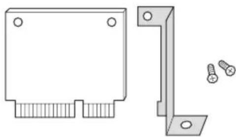
1.3 WiFi-802.11ac Module and ASRock WiFi 2.4/5 GHz Antenna
WiFi-802.11ac + BT Module
This motherboard comes with an exclusive WiFi 802.11 a/b/g/n/ac + BT v4.0 module that offers support for WiFi 802.11 a/b/g/n/ac connectivity standards and Bluetooth v4.0. WiFi + BT module is an easy-to-use wireless local area network (WLAN) adapter to support WiFi + BT. Bluetooth v4.0 standard features Smart Ready technology that adds a whole new class of functionality into the mobile devices. BT 4.0 also includes Low Energy Technology and ensures extraordinary low power consumption for PCs. The 2T2R WiFi solution sets a WiFi high speed standard and offers max link rate up to 867Mbps.
* The transmission speed may vary according to the environment.
* The WiFi + BT module is supported under Windows ^® 8.1 / 8.1 64-bit / 8 / 8 64-bit / 7 / 7 64-bit only.

text_image
WiFi + BT Module ASRock WiFi 2.4/5 GHz Antenna Antenna PortsWiFi Module and SMA Wi-Fi Antenna Cables Installation Guide
natural_image
Technical drawing of a mechanical bracket and corner joint with screws (no text or symbols)Step 1
Prepare the WiFi Module, WiFi Module Bracket, and the two screws (M2*3) that come with the package. Prepare a Phillips #0 screwdriver.
natural_image
Mechanical component diagram showing a lever and pin assembly (no text or symbols)Step 2
Attach the WiFi Module Bracket to the WiFi card, aligning the screw hole on the WiFi card with the screw hole on the bracket. Use the screw to attach the bracket and the WiFi card, but do not tighten the screw.
natural_image
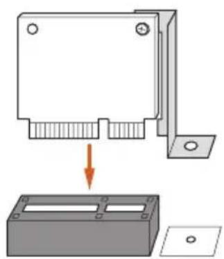
Diagram showing a mechanical assembly with a bracket and a base plate, no text or symbols presentStep 3
Insert the WiFi Module Card into the vertical mini PCI Express slot (MPCIE1).

natural_image
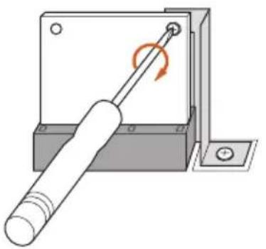
Mechanical assembly diagram showing a screwdriver inserted into a housing with a rotating knob (no text or symbols)Step 4
Tighten the screw that holds the card in place.
natural_image
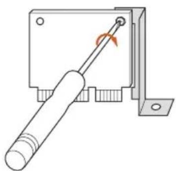
Mechanical assembly diagram showing a rotating shaft and housing component (no text or symbols)Step 5
Tighten the screw that attaches the WiFi Module Bracket to the WiFi card (installed in Step 2).
Step 6
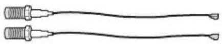
Prepare the SMA Wi-Fi Antenna Cables that come with the package.
natural_image
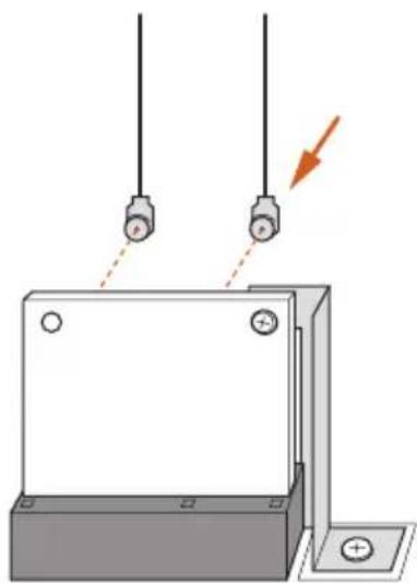
Diagram of a mechanical or electrical component with two hanging connectors and a downward arrow indicating force or direction (no text or symbols present)Step 7
Attach the SMA Wi-Fi Antenna Cables to the WiFi Module.
natural_image
Diagram of a mechanical assembly with wires and components, enclosed in an orange circle (no text or symbols)
natural_image
Pure electrical circuit lines without any symbolsStep 8
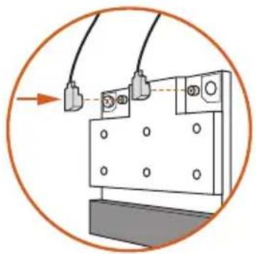
Insert the RP-SMA Wi-Fi Antenna Connectors to the antenna ports on the I/O shield
natural_image
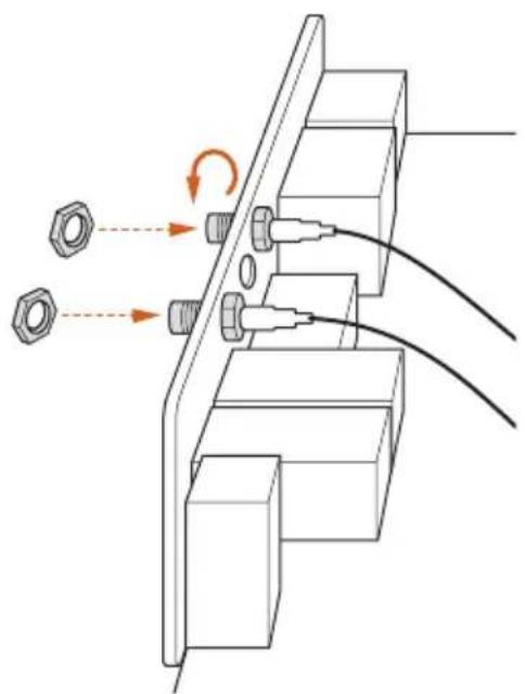
Technical diagram of a mechanical assembly with bolts and wires, no visible text or symbolsStep 9
Fasten the screw nuts to secure the antenna connectors.
Chapter 2 Installation
This is an Mini-ITX form factor motherboard. Before you install the motherboard, study the configuration of your chassis to ensure that the motherboard fits into it.
Pre-installation Precautions
Take note of the following precautions before you install motherboard components or change any motherboard settings.
- Make sure to unplug the power cord before installing or removing the motherboard components. Failure to do so may cause physical injuries and damages to motherboard components.
- In order to avoid damage from static electricity to the motherboard's components, NEVER place your motherboard directly on a carpet. Also remember to use a grounded wrist strap or touch a safety grounded object before you handle the components.
- Hold components by the edges and do not touch the ICs.
- Whenever you uninstall any components, place them on a grounded anti-static pad or in the bag that comes with the components.
- When placing screws to secure the motherboard to the chassis, please do not over-tighten the screws! Doing so may damage the motherboard.
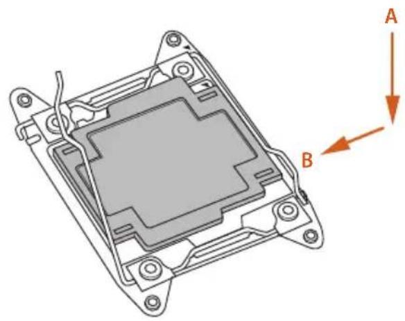
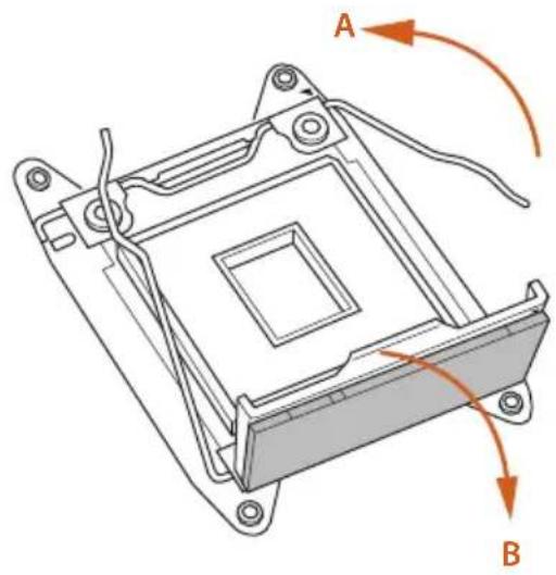
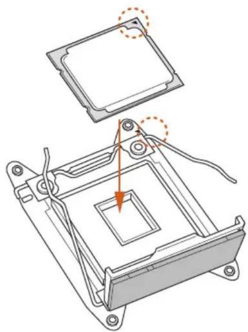
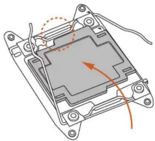
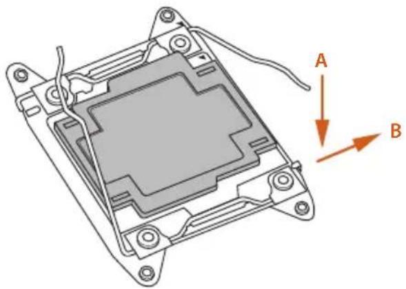
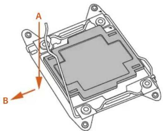
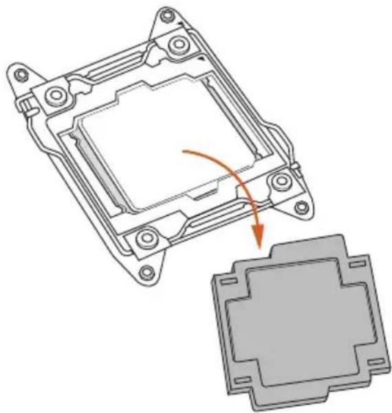
2.1 Installing the CPU

-
Before you insert the 2011-3-Pin CPU into the socket, please check if the PnP cap is on the socket, if the CPU surface is unclean, or if there are any bent pins in the socket. Do not force to insert the CPU into the socket if above situation is found. Otherwise, the CPU will be seriously damaged.
-
Unplug all power cables before installing the CPU.
CAUTION:
Please note that X99 platform is only compatible with the LGA 2011-3 socket, which is incompatible with the LGA 2011 socket (for X79 platform).
1

natural_image
3D diagram of a mechanical component with labeled arrows A and B indicating directional movement (no text or symbols beyond labels)2
natural_image
Technical line drawing of a mechanical component with labeled points A and B (no text or symbols beyond labels)3
natural_image
Technical line drawing of a mechanical component with labeled parts A and B, showing internal structure and mounting points (no text or symbols beyond labels)4
natural_image
Technical diagram of a computer processor's internal structure showing mounting and disassembly components (no text or labels)5
natural_image
Technical diagram of a mechanical component with highlighted internal structure and orange arrows indicating motion (no text or symbols)6
natural_image
Technical line drawing of a mechanical component with labeled points A and B, showing internal structure and mounting brackets (no text or symbols beyond labels)7
natural_image
Technical diagram of a mechanical component with labeled parts A and B, showing internal structure and mounting holes (no text or symbols beyond labels)8
natural_image
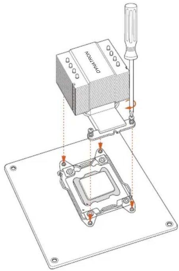
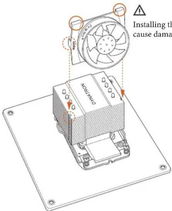
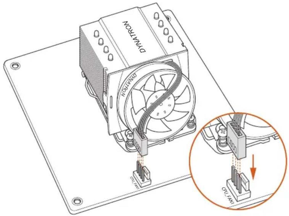
Technical illustration of a mechanical component with an arrow indicating a transformation or assembly (no text or symbols present)2.2 Installing the CPU Fan and Heatsink

- Before you installed the heatsink, you need to spray thermal interface material between the CPU and the heatsink to improve heat dissipation.
- This motherboard supports this free bundled CPU cooler or other CPU coolers for Narrow ILM (LGA 2011/LGA2011-v3 platform).
1
text_image
DTM PRON2
text_image
DVM-TRON Installing the cause damaInstalling the CPU fan upside down may cause damage.
3
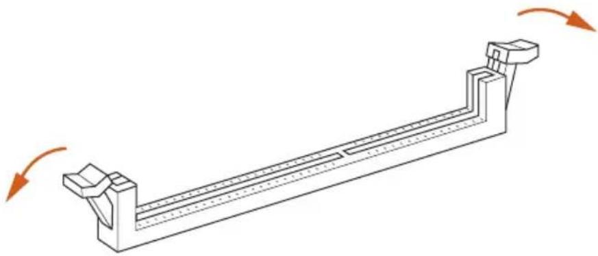
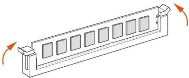
This motherboard provides two 288-pin DDR4 (Double Data Rate 4) DIMM slots, and supports Dual Channel Memory Technology.

- For dual channel configuration, you always need to install identical (the same brand, speed, size and chip-type) DDR4 DIMM pairs.
- It is unable to activate Dual Channel Memory Technology with only one memory module installed.
- It is not allowed to install a DDR, DDR2 or DDR3 memory module into a DDR4 slot; otherwise, this motherboard and DIMM may be damaged. otherwise, this motherboard and DIMM may be damaged.

The DIMM only fits in one correct orientation. It will cause permanent damage to the motherboard and the DIMM if you force the DIMM into the slot at incorrect orientation.
1
natural_image
Technical line drawing of a mechanical support structure with rotational arrows indicating motion (no text or symbols)2

natural_image
Illustration of hands assembling a mechanical component with a highlighted section (no text or symbols)3
natural_image
Isometric line drawing of a rectangular electronic component with multiple square slots and directional arrows indicating rotation (no text or symbols)2.4 Expansion Slots (PCI Express Slots)
There is 1 PCI Express slot and 1 mini-PCI Express slot on the motherboard.

Before installing an expansion card, please make sure that the power supply is switched off or the power cord is unplugged. Please read the documentation of the expansion card and make necessary hardware settings for the card before you start the installation.
PCIe slot:
PCIE1 (PCIe 3.0 x16 slot) is used for PCI Express x16 lane width graphics cards.
mini-PCIe slot:
MPCIE1 (mini-PCIe slot) is used for WiFi module.
2.5 Jumpers Setup
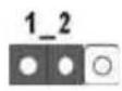
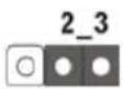
The illustration shows how jumpers are setup. When the jumper cap is placed on the pins, the jumper is "Short". If no jumper cap is placed on the pins, the jumper is "Open". The illustration shows a 3-pin jumper whose pin1 and pin2 are "Short" when a jumper cap is placed on these 2 pins.
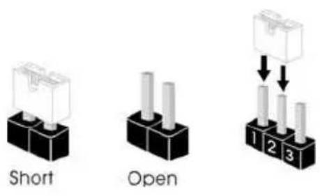
Clear CMOS Jumper (CLRCMOS1)
(see p.6, No. 19)
Clear CMOSDefault
CLRCMOS1 allows you to clear the data in CMOS. To clear and reset the system parameters to default setup, please turn off the computer and unplug the power cord from the power supply. After waiting for 15 seconds, use a jumper cap to short pin2 and pin3 on CLRCMOS1 for 5 seconds. However, please do not clear the CMOS right after you update the BIOS. If you need to clear the CMOS when you just finish updating the BIOS, you must boot up the system first, and then shut it down before you do the clear-CMOS action. Please be noted that the password, date, time, and user default profile will be cleared only if the CMOS battery is removed.

- The Clear CMOS Switch has the same function as the Clear CMOS jumper.
- If you clear the CMOS, the case open may be detected. Please adjust the BIOS option "Clear Status" to clear the record of previous chassis intrusion status.
2.6 Onboard Headers and Connectors

Onboard headers and connectors are NOT jumpers. Do NOT place jumper caps over these headers and connectors. Placing jumper caps over the headers and connectors will cause permanent damage to the motherboard.
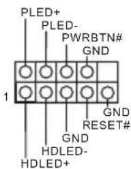
System Panel Header (9-pin PANEL1) (see p.6, No. 9)
text_image
PLED+ PLED- PWRBTN# GND 1 GND RESET# GND HDLED- HDLED+Connect the power switch, reset switch and system status indicator on the chassis to this header according to the pin assignments below. Note the positive and negative pins before connecting the cables.

PWRBTN (Power Switch):
Connect to the power switch on the chassis front panel. You may configure the way to turn off your system using the power switch.
RESET (Reset Switch):
Connect to the reset switch on the chassis front panel. Press the reset switch to restart the computer if the computer freezes and fails to perform a normal restart.
PLED (System Power LED):
Connect to the power status indicator on the chassis front panel. The LED is on when the system is operating. The LED keeps blinking when the system is in S1/S3 sleep state. The LED is off when the system is in S4 sleep state or powered off (S5).
HDLED (Hard Drive Activity LED):
Connect to the hard drive activity LED on the chassis front panel. The LED is on when the hard drive is reading or writing data.
The front panel design may differ by chassis. A front panel module mainly consists of power switch, reset switch, power LED, hard drive activity LED, speaker and etc. When connecting your chassis front panel module to this header, make sure the wire assignments and the pin assignments are matched correctly.
Power LED Header
(3-pin PLED1)
(see p.6, No. 6)

PLED- PLED+ PLED+
Serial ATA3 Connectors
(SATA3_0_1:
see p.6, No. 10)
(SATA3_2_3:
see p.6, No. 11)
(SATA3_4:
see p.6, No. 17)
(SATA3_5:
see p.6, No. 16)
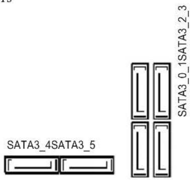
text_image
SATA3_4SATA3_5 SATA3_0_1SATA3_2_3Please connect the chassis power LED to this header to indicate the system's power status.
These six SATA3
connectors support SATA data cables for internal storage devices with up to 6.0 Gb/s data transfer rate. The SATA3_4, SATA3_5 are shared with the SATA Express connector (SATAE_4_5).
* RAID is supported on SATA3_0 \~ SATA3_5 ports only.
Serial ATA Express
Connector
(SATAE_4_5:
see p.6, No. 15)
SATA3_4 SATA3_5SATAE_4_5
Please connect either
SATA or PCIe storage devices to this connector. The SATA Express connector is shared with the SATA3_4 and the SATA3_5.
USB 2.0 Header
(9-pin USB3_4)
(see p.6, No. 8)
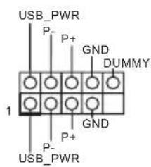
text_image
USB_PWR P- P+ GND DUMMY 1 P+ GND P- USB_PWRBesides two USB 2.0 ports on the I/O panel, there is one header on this motherboard. This USB 2.0 header can support two ports.
USB 3.0 Header (19-pin USB3_5_6) (see p.6, No. 14)

text_image
IntA_P_D+ IntA_P_D- GND IntA_P_SSIX+ GND IntA_P_SSRX+ Vbus Vbus IntA_P_SSRX- IntA_P_SSRX+ GND IntA_P_SSIX+ GND IntA_P_D- InA_P_D+ 1Besides four USB 3.0 ports on the I/O panel, there is one header on this motherboard. This USB 3.0 header can support two ports.
Front Panel Audio Header (9-pin HD_AUDIO1) (see p.6, No. 18)
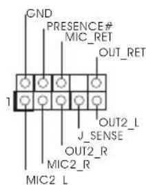
text_image
GND PRESENCE# MIC_RET OUT_RET 1 J_SENSE OUT2_L J_SENSE MIC2_R MIC2_LThis header is for connecting audio devices to the front audio panel.

- High Definition Audio supports Jack Sensing, but the panel wire on the chassis must support HDA to function correctly. Please follow the instructions in our manual and chassis manual to install your system.
- If you use an AC'97 audio panel, please install it to the front panel audio header by the steps below:
A. Connect Mic_IN (MIC) to MIC2_L.
B. Connect Audio_R (RIN) to OUT2_R and Audio_L (LIN) to OUT2_L.
C. Connect Ground (GND) to Ground (GND).
D. MIC_RET and OUT_RET are for the HD audio panel only. You don't need to connect them for the AC'97 audio panel.
E. To activate the front mic, go to the "FrontMic" Tab in the Realtek Control panel and adjust "Recording Volume".
Chassis Speaker Header (4-pin SPEAKER1) (see p.6, No. 12)
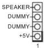
Please connect the chassis speaker to this header.
Chassis Fan Connectors (4-pin CHA_FAN1) (see p.6, No. 13)
Please connect fan cables to the fan connectors and match the black wire to the ground pin. CHA_FAN fan speed can be controlled through UEFI or A-Tuning.
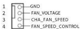
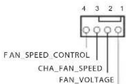
(3-pin CHA_FAN2) (see p.6, No. 4)
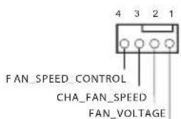
text_image
FAN_SPEED_CONTROL CHA_FAN_SPEED FAN_VOLTAGECPU Fan Connector (4-pin CPU_FAN1) (see p.6, No. 7)

This motherboard provides a 4-Pin CPU fan (Quiet Fan) connector. If you plan to connect a 3-Pin CPU fan, please connect it to Pin 1-3.
ATX Power Connector (24-pin ATXPWR1) (see p.6, No. 1)
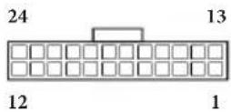
This motherboard provides a 24-pin ATX power connector. To use a 20-pin ATX power supply, please plug it along Pin 1 and Pin 13.
ATX 12V Power Connector (8-pin ATX12V1) (see p.6, No. 5)
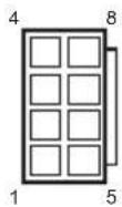
This motherboard provides an 8-pin ATX 12V power connector. To use a 4-pin ATX power supply, please plug it along Pin 1 and Pin 5.
Chassis Intrusion Header (2-pin CI1) (see p.6, No. 2)

This motherboard supports CASE OPEN detection feature that detects if the chassis cove has been removed. This feature requires a chassis with chassis intrusion detection design.
TPM Header (17-pin TPMS1) (see p.6, No. 20)

text_image
PCICLK FRAME PCIRST# LAD3 +3V LAD0 +3VSB GND 1 GND SMB_CLK_MAIN SMB_DATA_MAIN LAD2 LAD1 GND S_PWRDWN# SERIRQ# GNDThis connector supports Trusted Platform Module (TPM) system, which can securely store keys, digital certificates, passwords, and data. A TPM system also helps enhance network security, protects digital identities, and ensures platform integrity.
2.7 Smart Switches
The motherboard has a Clear CMOS Switch, allowing users to clear the CMOS values.
Clear CMOS Switch
(CLRCBTN)
(see p.8, No. 14)
Clear CMOS Switch
allows users to quickly
clear the CMOS values.

This function is workable only when you power off your computer and unplug the power supply.
2.8 M.2\_SSD (NGFF) Module Installation Guide
The M.2, also known as the Next Generation Form Factor (NGFF), is a small size and versatile card edge connector that aims to replace mPCIe and mSATA. The Ultra M.2 Socket (M2) can accommodate either a M.2 SATA3 6.0 Gb/s module or a M.2 PCI Express module up to Gen3 x4 (32 Gb/s).
Installing the M.2\_SSD (NGFF) Module
natural_image
Pure technical line drawing of a rectangular component with internal features and a small symbol at the bottom right (no text or labels)Step 1
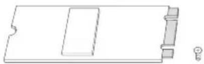
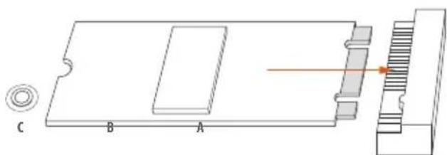
Prepare a M.2_SSD (NGFF) module and the screw.
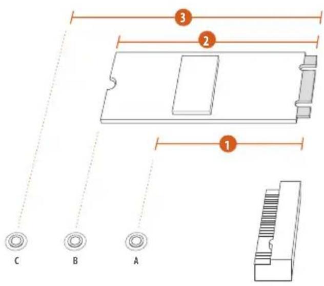
text_image
C B A 1 2 3Step 2
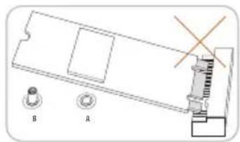
Depending on the PCB type and length of your M.2_SSD (NGFF) module, find the corresponding nut location to be used.
No.123
Nut Location A B C
PCB Length 4.2cm 6cm 8cm
Module Type Type 2242
Type2260 Type 2280

natural_image
Three circular diagrams labeled A, B, and C showing different mechanical or electrical configurations with directional arrows (no text or symbols beyond labels)
Step 3
Move the standoff based on the module type and length.
The standoff is placed at the nut location C by default. Skip Step 3 and 4 and go straight to Step 5 if you are going to use the default nut.
Otherwise, release the standoff by hand.


Step 4
Peel off the yellow protective film on the nut to be used. Hand tighten the standoff into the desired nut location on the motherboard.
natural_image
Technical diagram of a mechanical assembly with labeled components A and B (no text or symbols beyond labels)Step 5
Align and gently insert the M.2 (NGFF) SSD module into the M.2 slot. Please be aware that the M.2 (NGFF) SSD module only fits in one orientation.
natural_image
Technical diagram of a mechanical assembly with labeled components A, B, and C, showing internal components and a highlighted section (no text or symbols beyond labels)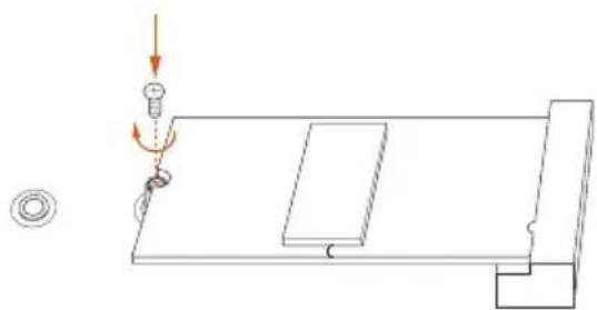
natural_image
Pure technical diagram showing a mechanical setup with a spring, pulley, and base plate (no text or symbols)Step 6
Tighten the screw with a screwdriver to secure the module into place. Please do not overtighten the screw as this might damage the module.
M.2\_SSD (NGFF) Module Support List
PCIe Interface SATA Interface
Plector PX-AG256M6e ADATA AXNS381E-128GM-B
Plector PX-AG512M6e ADATA AXNS381E-256GM-B
SanDisk SD6PP4M-128G Crucial CT120M500SSD4/120G
SanDisk SD6PP4M-256G Crucial CT240M500SSD4/240G
Samsung XP941-512G (MZHPU512HCGL) Intel SSDSCKGW080A401/80G
Samsung SH2280S3/480G Kingston RBU-SNS8400S3/180GD
Samsung SM951 (MZHPV256HDGL)
For the latest updates of M.2_SSD (NFGG) module support list, please visit our website for details: http://www.asrock.com
1 Einleitung
Serial-ATA-III-Anschlüsse
(SATA3_0_1:
siehe S. 1, Nr. 10)
(SATA3_2_3:
siehe S. 1, Nr. 11)
(SATA3_4:
siehe S. 1, Nr. 17)
(SATA3_5:
siehe S. 1, Nr. 16)
SATA3_4SATA3_5
SATA3_0_1SATA3_2_3
- FCC, CE, WHQL - ErP/EuP Ready (alimentation ErP/EuP ready requise)
- 6 x Connettori SATA3 6,0 Gb/s, supportano RAID (RAID 0, RAID 1, RAID 5, RAID 10, Intel Rapid Storage Technology 13), NCQ, AHCI e Hot Plug
conector SATA Express
(SATAE_4_5).
* RAID é compatível
conector SATA Express
é compartilhado com
o Soquete SATA3_4 e
SATA3_5.
Suportes USB 2.0
(USB3_4 de 9 pinos)
(ver p.1, N.° 8)

text_image
USB_PWR P- P+ GND DUMMY 1 P+ GND P- USB_PWR(3-pin CHA_FAN2) (bkz sf.1, No. 4)
text_image
FAN_SPEED_CONTROL CHA_FAN_SPEED FAN_VOLTAGEtext_image
Short OpenClear CMOS 점퍼
(CLRCMOS1)
If you need to contact ASRock or want to know more about ASRock, you're welcome to visit ASRock's website at http://www.asrock.com; or you may contact your dealer for further information. For technical questions, please submit a support request form at http://www.asrock.com/support/tsd.asp
ASRock Incorporation
2F., No.37, Sec. 2, Jhongyang S. Rd., Beitou District,
Taipei City 112, Taiwan (R.O.C.)
ASRock EUROPE B.V.
Bijsterhuizen 11-11
6546 AR Nijmegen
The Netherlands
Phone: +31-24-345-44-33
Fax: +31-24-345-44-38
ASRock America, Inc.
13848 Magnolia Ave, Chino, CA91710
U.S.A.
Phone: +1-909-590-8308
Fax: +1-909-590-1026
For the following equipment:
Motherboard
| (Product Name) |
| X99E-ITX/ac / ASRock |
| (Model Designation / Trade Name) |
ASRock Incorporation
| (Manufacturer Name) |
| 2F., No.37, Sec. 2, Jhongyang S. Rd., Beitou District, Taipei City 112, Taiwan (R.O.C.) |
(Manufacturer Address)
is herewith confirmed to comply with the requirements set out in the Council Directive on the Approximation of the Laws of the Member States relating to Electromagnetic Compatibility Directive (2004/108/EC) and Safety Directive (2006/95/EC), the following standards are applied:
EN 55022: 2006+A1:2007
EN 61000-3-2: 2009
EN 61000-3-3:2008
EN 55024: 1998 + A1:2001 + A2:2003
IEC 61000-4-2: 2008;
IEC 61000-4-3: 2010; IEC 61000-4-4: 2010;
IEC 61000-4-5: 2005; IEC 61000-4-6: 2008;
IEC 61000-4-8: 2009; IEC 61000-4-11: 2004;
☑ EN 60950-1:2005 + A1:2009
IEC 60950-1: 2006 + A11:2009 + A1:2010 + A12:2011
The following manufacturer / importer or authorized representative established within the EUT is responsible for this declaration:
ASRock EUROPE B.V.
| (Company Name) |
| Bijsterhuizen 3151 6604 LV Wijchen The Netherlands |
(Company Address)
Person responsible for making this declaration:

(Name, Surname)
A.V.P
(Position / Title)
April 3, 2015
(Date)