21084 - Compressor Eufab - Free user manual and instructions
Find the device manual for free 21084 Eufab in PDF.

User questions about 21084 Eufab
0 question about this device. Answer the ones you know or ask your own.
Ask a new question about this device
Download the instructions for your Compressor in PDF format for free! Find your manual 21084 - Eufab and take your electronic device back in hand. On this page are published all the documents necessary for the use of your device. 21084 by Eufab.
USER MANUAL 21084 Eufab
natural_image
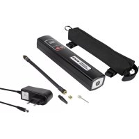
Exterior view of a black EUFAB electric pressure charger with digital display and tool accessories (no readable text or symbols beyond branding)© EAL GmbH, 21084 12.2022
D Art.-Nr.: 21084
DUAL POWER KOMPRESSOR
12V/230V
Operating instructions 8
FR Réf. art. 21084
COMPRESSEUR DOUBLE PUISSANCE
12 V / 230 V
natural_image
3D model of a rectangular electronic device with labeled ports (no text or symbols beyond labels)
text_image
Diagram of a device rear panel with numbered labels pointing to different components
natural_image
Interior view of a black plastic automotive chassis with internal components and mounting holes (no text or symbols visible)natural_image
Coiled black cable with two connectors and a numbered label (13) on the left, no visible text or symbols beyond the label.natural_image
Coiled black cable with a terminal plug and label (14), no readable text or symbols beyond the label
Bild 1: Übersicht
6.2 BETRIEB DES KOMPRESSORS
natural_image
Close-up of a black mechanical tool with a curved arrow indicating motion (no text or symbols visible)Bild 2
natural_image
Two black mechanical components with a downward arrow indicating motion (no text or symbols)Bild 3
natural_image
Close-up of a black mechanical component with a curved arrow indicating rotation or movement (no text or symbols visible)Bild 4
natural_image
Close-up of a black mechanical tool with curved handle and lever (no visible text or symbols)Bild 5
text_image
Technical diagram of a mechanical component with numbered parts labeled 18, 19, and 20Read the operating instructions through carefully prior to initial use and observe all of the safety notes!
Not observing such may lead to personal injuries, damages to the device or to your property!
Store the original packaging, the receipt and these instructions so that they may be consulted at a later date! When passing on the product, please include these operating instructions as well.
Please check the contents of package for integrity and completeness prior to use!
1. PROPER USE OF THE PRODUCT
The dual power compressor is designed for universal use e.g. for pumping car, motorbike and bicycle tyres, sport balls and, inflatable toys.
It may be connected to the 12 V on-board network of a vehicle or the 230 V household network. The manometer can be used during the filling process to monitor the pressure.
This device is not designed to be used by children or persons with limited mental abilities or without experience and/or lack of required specialist knowledge. Keep children away from the device.
The device is not designated for commercial use.
Use according to the intended purpose also includes the observance of all information in these operating instructions, particularly the observance of the safety notes. Any other utilisation is considered to be contrary to the intended purpose and may lead to material damages or personal injuries. EAL GmbH assumes no liability for damages resulting from improper use.
2. SCOPE OF DELIVERY
1 x Dual Power Compressor
1 x Car connection cable for 12 V on-board socket
1 x Connection cable for 230 V house socket
2 x Fuse, fast 15 A 250 V, 6 x 30
1 x Adapter ø 5 mm
1 x Adapter ø 8 mm
1 x Ball adapter
1 x Operating instructions
3. SPECIFICATIONS
Input voltage: 230 V 50 Hz AC 12 V DC
Maximum pressure: 10.3 bar / 150 psi
Max. Power: 120 W
Dimensions (L x W x H): approx. 22 x 13 x 7.5 [cm]
Weight (without accessories): approx. 0.950 kg
Length of air hose: approx. 0.50 m
Length of 12 V-cable: approx. 3.50 m
Length of 230 V-cabl: approx. 1.50 m
4. SAFETY PRECAUTIONS

- The warning symbol indicates all instructions which are important for safety. Always follow these, otherwise you could injure yourself or damage the device.
• Children may not play with the device. - Cleaning and user maintenance may not be carried out by children without supervision.
- Do not treat packaging material carelessly. This may become a dangerous plaything for a child!
- Only use this product for its designated purpose!
- Do not manipulate or disassemble the device!
- For the objects to be inflated, do not increase the air pressure beyond the recommendations of the manufacturer!
- Protect the compressor and its components from damp!
- Do not leave an operating compressor unattended!
- Keep children away and do not allow children to operate this device!
- Never cover the ventilation slots of the compressor during operation.
- If the compressor emits unusual noises or overheats, switch it off immediately and give it at least 20 minutes to cool down!
- Check the compressor before use. Damaged, cracked or broken components should be repaired only by qualified technicians!
- Never expose the compressor to frost, rain or temperatures above 30^ or below - 30^ !
- Never use on people or animals!
- Make sure that the hose and cable are not exposed to sharp edges, oil or objects that are too hot!
- When filling, always pay attention to the correct air pressure (consult the operating instructions of your vehicle for information). The compressor is able to supply a pressure of up to 10.3 bar. If the pressure is too high, there is a risk of explosion and injury.
- Never allow the compressor to operate for longer than 10 minutes without a pause, otherwise there is a risk of overheating. Switch the compressor off after 10 minutes of use and allow it to cool down fully (at least 20 minutes) before starting it up again.
- The compressor may discharge the battery of your vehicle if the motor is switched off.
- If you use the compressor with the vehicle motor running, ensure good ventilation in the garage or hall. There is a risk of poisoning!
- Separate the compressor from the power supply when it is not in use.

- For your own safety, only use accessories and spare parts that are stated in these instructions or that are recommended by the manufacturer!
5. EXPLANATIONS OF SYMBOLS

Complies with EC directives
Labelled electrical products may not be disposed of in the household waste
Devices with this symbol may only be operated indoors (dry environment)

Insulated housing (protection class II).

Read the operating instructions
6. OPERATING INSTRUCTIONS
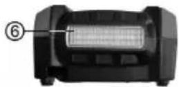
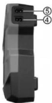
6.1 OVERVIEW
1 ON / OFF switch
2 Switch for LED work light
3 Display with setting buttons
4 12 V input
5 230 V input
6 LED work light
7 Air hose with autovalve connection
natural_image
3D model of a rectangular electronic device with labeled ports (no text or symbols beyond labels)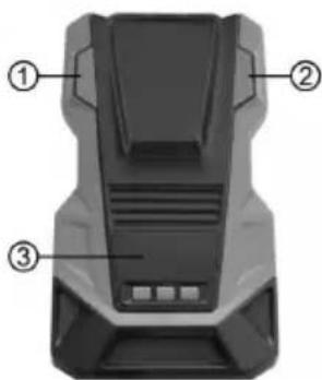
text_image
Diagram of a device rear panel with numbered labels pointing to different components
natural_image
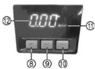
Interior view of a black automotive battery pack with internal compartments and a labeled component (no text or symbols)8 (+) button
9 (R) button for setting units
10 (-) button
11 Unit for pressure
12 Pressure indicator
13 12 V car connection cable
text_image
0.00 ⑫ ⑪ ⑧ ⑨ ⑩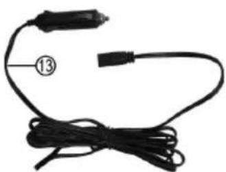
natural_image
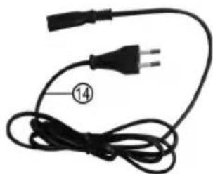
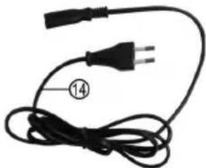
Coiled black cable with two connectors, labeled with number 13 (no text or symbols on the cable itself)14 230 V connection cable
15 Ball adapter
16 Adapter ∅ 8 mm
17 Adapter ∅ 5 mm
natural_image
Coiled black electrical plug with terminal connector, labeled with number 14 (no text or symbols on the cable itself)
Figure 1: Overview
6.2 OPERATING THE COMPRESSOR
Make sure that the compressor is switched off before connecting it. The ON / OFF switch (position1 in the overview) must not be depressed.
In order to be able to work with the compressor, first take the air hose (Position 7 in the overview) from its holder on the back of the unit.
6.2.1 CONNECTING THE COMPRESSOR

CAUTION
Do not connect the compressor to both the 230 V household connection and the 12 V socket of your vehicle at the same time.
CONNECTION TO THE 12 V VEHICLE SOCKET:
Insert the appliance plug of the 12 V vehicle connection cable (position 13 in the overview) into the 12 V input (position 4 in the overview) of the compressor. Then insert the vehicle plug of the connection cable into the vehicle socket. On some vehicles, the ignition must be switched on for the on-board socket to be active.
The compressor may discharge the battery of your vehicle if the motor is switched off. If you use the compressor with the vehicle motor running, ensure good ventilation in the garage or hall. There is a risk of poisoning!
CONNECTION TO THE 230 V DOMESTIC SOCKET:
Plug the appliance plug of the 230 V connection cable (position 14 in the overview) into the 230 V input (position 5 in the overview) of the compressor. Then insert the plug of the connection cable into the house socket.
After the compressor is electrically connected, the display (position 3 in the overview) is activated.
6.2.2 PRESETTING THE AIR PRESSURE
Select the unit in which the air pressure is to be displayed by pressing the (R) button (position 9 in the overview). By pressing repeatedly, the following units can be set: PSI - BAR - kg/cm². By pressing the (+) button (position 8 in the overview) the value can be increased, by pressing the (-) button (position 10 in the overview) the value can be decreased. overview) the value can be lowered.
During the setting process, the display fl ashes. If no more settings are made, the display shows the value 0.00 continuously after approx. 3 seconds.

The last settings are saved. After switching on again, they are set again. If you now want to work with other values, you must carry out a new presetting.
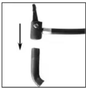
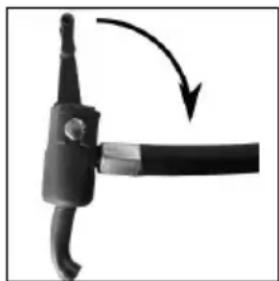
6.3 FILLING A TYRE USING THE CAR VALVE (SCHRADER VALVE)
Open the lock on the valve connection
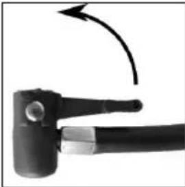
natural_image
Close-up of a black mechanical tool with a curved arrow indicating rotation (no text or symbols visible)Figure 2
Place the valve connection on the valve
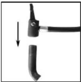
natural_image
Close-up of a black cable with a pointed tip and a separate curved component, showing a downward arrow (no text or symbols)Figure 3
Lock the valve connection
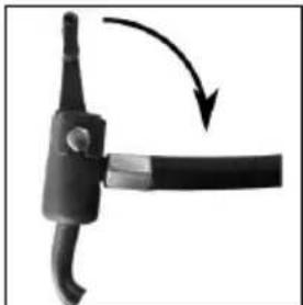
natural_image
Close-up of a black mechanical component with a curved arrow indicating rotation or movement (no text or symbols)Figure 4
You can now fill the tyre using the compressor
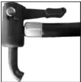
natural_image
Close-up of a black mechanical tool with curved handle and lever (no visible text or symbols)Figure 5
Press the ON / OFF switch (position 1 in the overview) to start the fi lling process. During the fi lling process, the current air pressure is shown in the display. When the preset
pressure is reached, the compressor switches off automatically.
switches off automatically. After switching off, press the ON/OFF switch.

When filling, always pay attention to the correct air pressure (consult the operating instructions of your vehicle for information). The compressor is able to supply a pressure of up to 10.3 bar. If the pressure is too high, there is a risk of explosion and injury.

Never allow the compressor to operate for longer than 10 minutes without a pause, otherwise there is a risk of overheating. Switch the compressor off after 10 minutes of use and allow it to cool down fully (at least 20 minutes) before starting it up again. Never leave the compressor to operate unattended.
After fi lling a tyre, check the tyre pressure again using a separate air pressure tester (e.g. at a fi lling station, vehicle workshop).
6.4 USING THE ADAPTER
Open the lock of the valve connection (Figure 2). Insert the appropriate adapter for the required purpose into the valve connection. Lock the valve connection (Figure 4). Insert the adapter into the fi lling connection of your leisure equipment (ball, infl atable toys etc.). Depending on version, it is possible that the adapter will need to be held firmly during the fi lling process. Remove the adapter from the valve connection by proceeding in reverse order, as described above.
6.5 CONVERSION TABLE PSI / BAR / KG/CM ^4
The units are converted as follows:
$$ 1 \mathrm{psi} = 0. 0 6 9 \mathrm{bar} = 0. 0 7 0 3 \mathrm{kg} / \mathrm{cm} ^ {2} $$
$$ 1 \mathrm{bar} = 1. 0 1 9 7 \mathrm{kg} / \mathrm{cm} ^ {2} = 1 4. 5 0 4 \mathrm{psi} $$
$$ 1 \mathrm{kg} / \mathrm{cm} ^ {2} = 1 4. 2 2 3 \mathrm{psi} = 0. 9 8 1 \mathrm{bar} $$
| psi bar kg/cm2 | |
| 10 0.7 | 0.7 |
| 20 1.4 | 1.4 |
| 30 2.1 | 2v1 |
| 40 2.8 | 2.8 |
| 50 3.5 | 3.5 |
| 60 4.1 | 4.2 |
| 70 4.8 | 4.9 |
| 80 5.5 | 5.6 |
| 90 6.2 | 6.3 |
| 100 6.9 | 7.0 |
| 110 7.6 | 7.7 |
| 120 8.3 | 8.4 |
| 130 9.0 | 9.1 |
| 140 9.7 | 9.8 |
| 150 10 | 4 10.5 |
| psi bar kg/cm2 | ||
| 0.5 | 7 | 0.5 |
| 1.0 | 15 1.1 | |
| 1.5 | 22 1.6 | |
| 2.0 | 29 2.2 | |
| 2.5 | 36 2.7 | |
| 3.0 | 44 3.3 | |
| 3.5 | 51 3.8 | |
| 4.0 | 58 4.4 | |
| 4.5 | 65 4.9 | |
| 5.0 | 73 5.5 | |
| 5.5 | 80 6.0 | |
| 6.0 | 87 6.6 | |
| 6.5 | 94 7.1 | |
| 7.0 102 | 7.7 | |
| 7.5 109 | 8.2 | |
| 8.0 116 | 8.8 | |
| 8.5 123 | 9v3 | |
| 9.0 131 | 9v9 | |
| 9.5 138 | 10v4 | |
| 10.0 | 145 11.0 | |
| psi | bar | kg/cm2 |
| 0.5 | 7 | 0.5 |
| 1.0 | 14 | 1.0 |
| 1.5 | 21 | 1,5 |
| 2.0 | 28 | 2.0 |
| 2.5 | 36 | 2.5 |
| 3.0 | 43 | 2.9 |
| 3.5 | 50 | 3.4 |
| 4.0 | 57 | 3.9 |
| 4.5 | 64 | 4.4 |
| 5.0 | 71 | 4.9 |
| 5.5 | 78 | 5.4 |
| 6.0 | 85 | 5.9 |
| 6.5 | 92 | 6.4 |
| 7.0 | 100 | 6.9 |
| 7.5 | 107 | 7.4 |
| 8.0 | 114 | 7.8 |
| 8.5 | 121 | 8.3 |
| 9.0 | 128 | 8.8 |
| 9.5 | 135 | 9.3 |
| 10.0 | 142 | 9.8 |
6.6 LED WORK LIGHT
The LED work light (position 6 in the overview) is switched on and off by pressing the switch (position 2 in the overview).
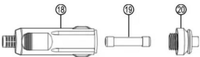
6.7 REPLACING THE FUSES
Rotate the tip (Position 20 in Figure 6) of the 12 V plug (Position 18 in Figure 6) anti-clockwise until it comes away from the plug and then remove. The fuse (Position 19 in Figure 6) is exposed and can be removed from the plug. Replace the fuse with another of the same strength (here glass fuse, fast 15 A 250 V, 6 x 30) and screw the tip back into the plug, Figure 6.
text_image
Technical diagram of a mechanical component with numbered parts labeled 18, 19, and 20Figure 6: Fuse in 12 V plug
6.8 TROUBLESHOOTING
| Error Possible cause Measure | ||
| The compressor does not workt | The connection cable is not connected correctly. | Check the connection of the cables and connect them correctly. |
| For vehicle operation: No voltage at the on-board socket. | Switch on the ignition of the vehicle. Check the fuse for the boron socket and replace it if necessary. | |
| The fuses in the plug of the 12 V car cable has tripped. | Replace the defective fuse, see section 6.7 | |
7. MAINTENANCE AND CARE
7.1 MAINTENANCE
When used according to the instructions, the Dual Power Compressor is maintenance-free. Store the compressor in a dry, frost-free location.
7.2 CARE
Switch the compressor off before cleaning, separate from the power supply. Clean the housing of the compressor with a soft, dry cloth. Do not use any aggressive cleaning agents or solvent-based cleaners. Never allow liquids to penetrate the housing.
8. NOTES REGARDING ENVIRONMENTAL PROTECTION
Do not dispose of electrical appliances in household waste! Discarded electrical and electronic equipment must be collected separately and recycled in an environmentally sound manner.
Contact your municipal or city government on how to dispose of old electronic equipment.
The materials are recyclable. You are making an important contribution to protecting our environment through recycling, material recycling or other forms of re-utilising old appliances!
Dispose of the compressor in accordance with the laws and conditions in your country.
9. CONTACT INFORMATION
EAL GmbH
42115 Wuppertal, Germany
+49 (0)202 42 92 83 0
text_image
Diagram of a device with labeled ports and numbered annotations (④ and ⑤)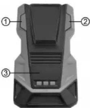
text_image
Diagram of a vehicle rear bumper with numbered labels pointing to different components
natural_image
Interior view of a black plastic automotive hood with internal compartments and a labeled component (no text or symbols)natural_image
Coiled black cable with two connectors and a numbered label (13) on the left, no visible text or symbols beyond the label.natural_image
Coiled black electrical plug with terminal connector, labeled with number 14 (no text or symbols on the cable itself)natural_image
Close-up of a black mechanical tool with a curved arrow indicating motion (no text or symbols visible)Figure 2
Placez le raccord de valve sur la valve
natural_image
Two black mechanical components with arrows indicating a transformation or assembly (no text or symbols visible)Figure 3
Verrouillez le raccord de valve
natural_image
Close-up of a black mechanical component with a curved handle and arrow indicating rotation (no text or symbols)Figure 4
natural_image
Close-up of a black mechanical tool with a curved handle and lever (no visible text or symbols)Figure 5
text_image
Technical diagram of a mechanical component with numbered parts labeled 18, 19, and 20natural_image
Black rectangular electronic device with labeled ports (no text or symbols beyond labels)
text_image
Diagram of a vehicle rear bumper with numbered labels pointing to different components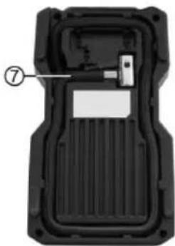
natural_image
Interior view of a black plastic automotive housing with internal compartments and a labeled component (no text or symbols)natural_image
Coiled black cable with two connectors and a label '13' on the left (no text or symbols on the cable itself)14 Aansluitkabel 230 V
15 Kogeladapter
16 Adapter ∅ 8 mm
17 Adapter ∅ 5 mm
natural_image
Coiled black electrical plug with terminal connector, labeled with number 14 (no text or symbols on the cable itself)natural_image
Close-up of a black mechanical tool with a curved arrow indicating motion (no text or symbols visible)Afbeelding 2
natural_image
Two black mechanical components with arrows indicating transformation or assembly (no text or symbols visible)Afbeelding 3
natural_image
Close-up of a black mechanical component with a curved arrow indicating rotation or movement (no text or symbols)Afbeelding 4
natural_image
Close-up of a black mechanical tool with curved handle and lever (no visible text or symbols)Afbeelding 5
text_image
Technical diagram of a mechanical component with numbered parts labeled 18, 19, and 20natural_image
3D model of a rectangular electronic device with labeled ports (no text or symbols beyond labels)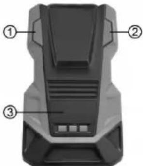
text_image
Diagram of a device rear panel with numbered labels pointing to different components
natural_image
Interior view of a black plastic automotive component with internal slots and a labeled part (no text or symbols)8 (+)
natural_image
Coiled black cable with a connector and label 13, no visible text or symbols beyond the numbernatural_image
Coiled black electrical plug with terminal connector, labeled with number 14 (no text or symbols on the plug itself)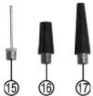
Figura 1: Panoramica
6.2 UTILIZZO DEL COMPRESSORE

natural_image
Close-up of a black mechanical tool with a curved arrow indicating motion (no text or symbols visible)Figura 2
natural_image
Two black mechanical components with arrows indicating a transformation or assembly (no text or symbols visible)Figura 3
natural_image
Close-up of a black mechanical component with a curved arrow indicating rotation (no text or symbols)Figura 4
natural_image
Close-up of a black mechanical tool with curved handle and lever (no visible text or symbols)Figura 5