16422 - Bike accessory Eufab - Free user manual and instructions
Find the device manual for free 16422 Eufab in PDF.
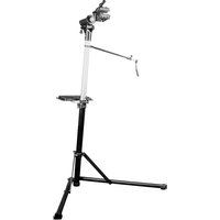
| Product type | Foldable and adjustable wall mount for bike |
| Brand | Eufab |
| Model | 16422 |
| Dimensions (unfolded) | Approx. 18 x 26 x 45 cm (W x H x D) |
| Dimensions (folded) | Approx. 42 x 26 x 10 cm (W x H x D) |
| Net weight | 1.050 kg |
| Maximum load | 30 kg |
| Support arm length | Max. 45 cm |
| Supplied items | 1 wall mount, 1 Allen key 5 mm, 4 heavy-duty wall plugs, 1 instruction manual |
| Intended use | Storage of bicycles on interior wall |
| Mounting type | Wall mounting with heavy-duty wall plugs (for stone or concrete walls) |
| Material | Steel (estimated) |
| Maintenance | Check screw connections regularly; clean with a dry cloth |
| Safety instructions | Observe maximum load; drill away from cables and pipes; check wall strength |
Frequently Asked Questions - 16422 Eufab
User questions about 16422 Eufab
0 question about this device. Answer the ones you know or ask your own.
Ask a new question about this device
Download the instructions for your Bike accessory in PDF format for free! Find your manual 16422 - Eufab and take your electronic device back in hand. On this page are published all the documents necessary for the use of your device. 16422 by Eufab.
USER MANUAL 16422 Eufab
natural_image
Black mechanical device with curved and straight ends, accompanied by six small metal fasteners (no text or symbols visible)© EAL GmbH, 16422, 12.2022
D Art.-Nr. 16422
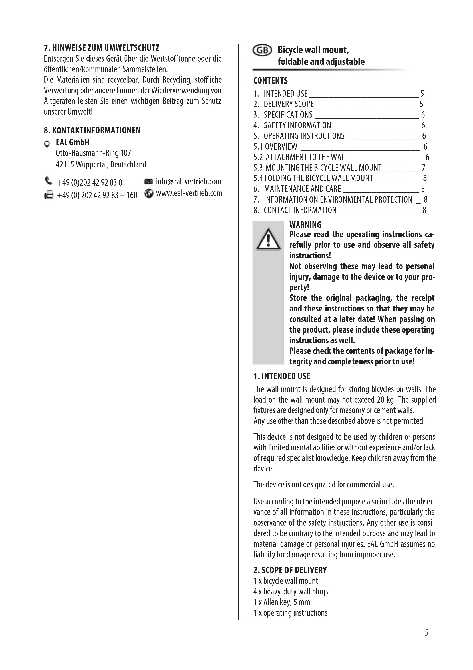
Bicycle wall mount, foldable and adjustable
Operating instructions ....5
FR Réf. 16422
1 x Inbusschlüssel, 5 mm
text_image
Technical diagram of a mechanical assembly with numbered components and exploded viewBild 1: Übersicht
natural_image
Diagram showing a drill bit with arrows pointing to a circular target, no text or symbols presentnatural_image
Diagram showing a device emitting a pipe into a circular container (no text or symbols)natural_image
Diagram showing a mechanical linkage or assembly with arrows pointing to specific points (no text or labels present)natural_image
Diagram of a mechanical component with a central shaft and bolt, set against a circular background (no text or symbols)natural_image
Diagram of a screw with a directional arrow indicating motion, set against a circular background (no text or symbols)natural_image
Technical diagram of a mechanical assembly with circular outline and labeled components (no readable text or symbols)natural_image
Technical line drawing of a mechanical component with a curved pipe and attached bracket (no text or symbols)natural_image
Technical line drawing of a mechanical component with curved and straight ends, showing rotational motion (no text or symbols)natural_image
Technical line drawing of a mechanical clamp or bracket assembly (no text or symbols)text_image
Technical diagram showing two mechanical assembly configurations with labeled parts and directional arrowsBild 15:
text_image
Technical diagram showing two mechanical assembly configurations with directional arrows and labeled partsnatural_image
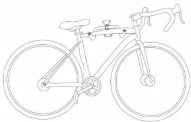
Line drawing of a bicycle with front wheel, rear wheel, and suspension bracket (no text or symbols)Bicycle wall mount, foldable and adjustable
CONTENTS
- INTENDED USE 5
- DELIVERY SCOPE 5
- SPECIFICATIONS 6
- SAFETY INFORMATION 6
- OPERATING INSTRUCTIONS 6
5.1 OVERVIEW 6
5.2 ATTACHMENT TO THE WALL 6
5.3 MOUNTING THE BICYCLE WALL MOUNT 7
5.4 FOLDING THE BICYCLE WALL MOUNT 8 - MAINTENANCE AND CARE 8
- INFORMATION ON ENVIRONMENTAL PROTECTION _ 8
- CONTACT INFORMATION 8
WARNING
Please read the operating instructions carefully prior to use and observe all safety instructions!
Not observing these may lead to personal injury, damage to the device or to your property!
Store the original packaging, the receipt and these instructions so that they may be consulted at a later date! When passing on the product, please include these operating instructions as well.
Please check the contents of package for integrity and completeness prior to use!
1. INTENDED USE
The wall mount is designed for storing bicycles on walls. The load on the wall mount may not exceed 20 kg. The supplied fixtures are designed only for masonry or cement walls.
Any use other than those described above is not permitted.
This device is not designed to be used by children or persons with limited mental abilities or without experience and/or lack of required specialist knowledge. Keep children away from the device.
The device is not designated for commercial use.
Use according to the intended purpose also includes the observance of all information in these instructions, particularly the observance of the safety instructions. Any other use is considered to be contrary to the intended purpose and may lead to material damage or personal injuries. EAL GmbH assumes no liability for damage resulting from improper use.
2. SCOPE OF DELIVERY
1 x bicycle wall mount
4 x heavy-duty wall plugs
1 x Allen key, 5 mm
1 x operating instructions
3. SPECIFICATIONS
Dimensions (W x H x D): approx. 18 (42 folded) x 26 x 35
(45 max. extended,
10 folded) [cm]
Weight: 1.050 kg
Length of support arm: max. 45 cm
Maximum load: 30 kg
4. SAFETY PRECAUTIONS

- The warning triangle sign indicates all instructions which are important for safety. Always follow these, otherwise you could injure yourself or damage the device.
• Children may not play with the device. - Cleaning and user maintenance may not be carried out by children without supervision.
- Do not treat packaging material carelessly. It may become a dangerous plaything for children!
- Only use this product for its designated purpose!
- Do not manipulate or disassemble the device!
- For your own safety, only use accessories and spare parts that are stated in these instructions or that are recommended by the manufacturer!
- Before mounting, ensure that the wall is suitable for the bike wall mount.
- The supplied fixtures are designed only for masonry or cement walls. For all other walls, please use attachment material that is suitable for the respective wall structure. If necessary, seek professional advice!
- The selection of an unsuitable installation location may result in injury or property damage.
- Before drilling any holes, ensure that you cannot damage any cables or pipes.
- Carry out the installation very conscientiously, since if the bicycle falls, it will not only result in expense consequential damages, but also an increased risk of injuries.
- Check all screw connections regularly. The screw connections may loosen over time with the loading and unloading of the wall mount.
5. OPERATING INSTRUCTIONS
5.1 OVERVIEW
text_image
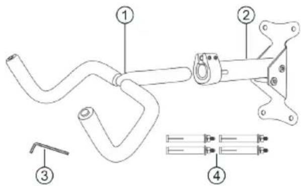
Technical diagram of a mechanical assembly with numbered components and labeled partsFigure 1: Overview
1 Support hook
2 Wall attachment with hinge mechanism
3 Allen key
4 Heavy-duty wall plug
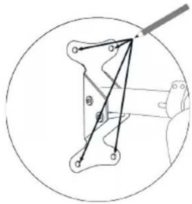
5.2 ATTACHMENT TO THE WALL
natural_image
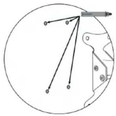
Pure mechanical linkage diagram without any text, numbers, or symbolsFigure 2: Marking the boreholes
text_image
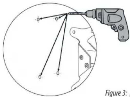
Figure 3:Figure 3: Drilling holes
text_image
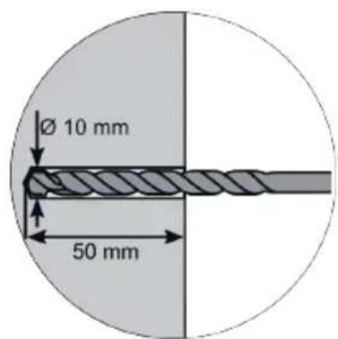
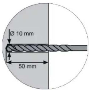
Ø 10 mm 50 mmFigure 4: Drilling depth and diameter
natural_image
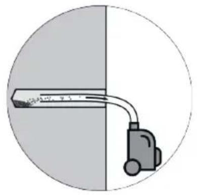
Diagram of a vacuum cleaner inside a circular chamber, showing airflow direction (no text or symbols)Figure 5: Removing the drilling dust
text_image
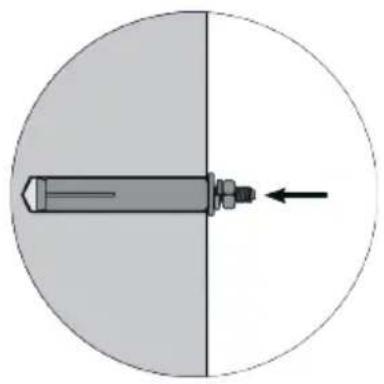
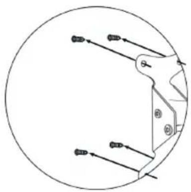
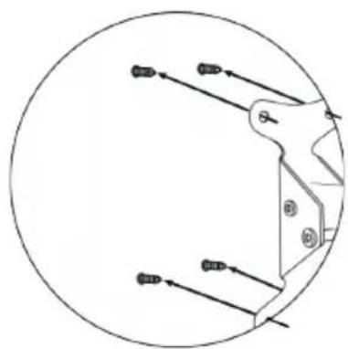
Diagram showing a mechanical linkage or alignment with labeled points and directional arrows, likely illustrating a mechanical or kinematic concept.Figure 6: Inserting the heavy-duty wall plugs
natural_image
Diagram of a bolt and nut assembly inside a circular housing, with an arrow indicating direction (no text or symbols)Figure 7: Inserting the heavy-duty wall plugs (detail)
natural_image
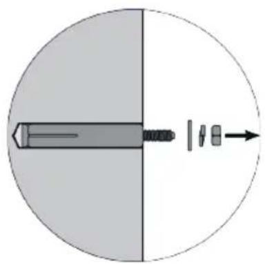
Diagram showing a screw inserted into a circular component with an arrow indicating direction (no text or symbols)Figure 8: Removing the nuts and washers
natural_image
Pure mechanical diagram showing a circular component with internal components and directional arrows (no text or symbols)Figure 9: Positioning the wall attachment
natural_image
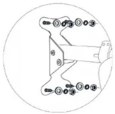
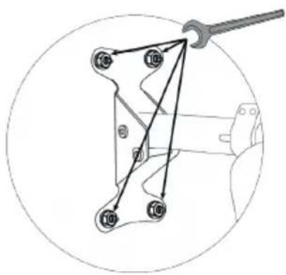
Technical line drawing of a mechanical assembly with numbered components (no text or symbols)Figure 10: Attaching the nuts and washers
flowchart
graph TD
    A["10"] --> B["18"]
    B --> C["7"]
    C --> D["16"]
    D --> E["10"]
    E --> F["9"]
    F --> G["10"]
    G --> H["10"]
    H --> I["10"]
    I --> J["10"]
    J --> K["10"]
    K --> L["10"]
    L --> M["10"]
    M --> N["10"]
    N --> O["10"]
    O --> P["10"]
    P --> Q["10"]
    Q --> R["10"]
    R --> S["10"]
    S --> T["10"]
    T --> U["10"]
    U --> V["10"]
    V --> W["10"]
    W --> X["10"]
    X --> Y["10"]
    Y --> Z["10"]
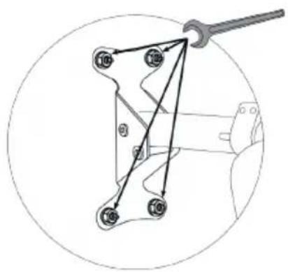
Figure 11: Tightening nuts
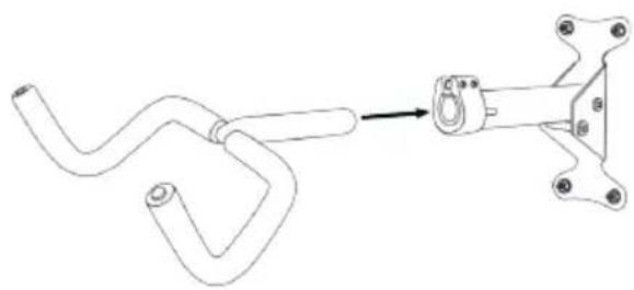
5.3 MOUNTING THE BICYCLE WALL MOUNT
natural_image
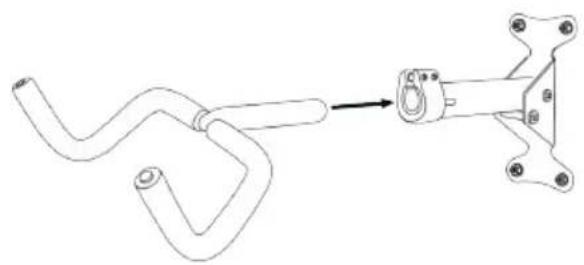
Technical line drawing of a mechanical component with a curved pipe and attached bracket (no text or symbols)Figure 12: Assembly
natural_image
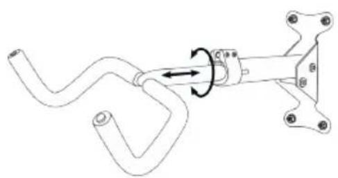
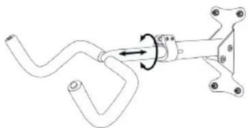
Mechanical diagram showing a rotating lever mechanism with no text or symbolsFigure 13: Alignment and adjustment
natural_image
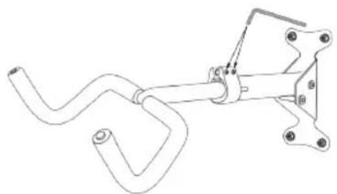
Technical line drawing of a mechanical clamp or bracket assembly (no text or symbols)Figure 14: Tightening Allen screws
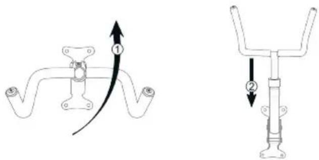
5.4 FOLDING THE BICYCLE WALL MOUNT
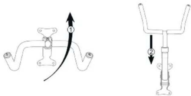
text_image
Technical diagram showing two mechanical components with labeled parts and directional arrows indicating motion or force.Figure 15: Folding the bicycle wall mount upwards
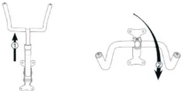
text_image
Technical diagram showing two mechanical components with directional arrows and numbered callouts indicating assembly or movement.Figure 16: Folding the bicycle wall mount downwards
natural_image
Line drawing of a bicycle with front wheel, rear wheel, and side seat (no text or symbols)Figure 17: Hanging the bike
6. MAINTENANCE AND CARE
Check all screw connections regularly. The screw connections may loosen over time with the loading and unloading of the wall mount.
The product is maintenance free and does not need any maintenance with the exception of occasional cleaning with soft, dry cloth. Do not use aggressive cleaning agents or chemical solutions since otherwise the surfaces will be damaged.
7. INFORMATION ON ENVIRONMENTAL PROTECTION
Please dispose of this device via the recycling bin or the public/municipal collection points.
The materials are recyclable. You make an important contribution to protecting our environment by recycling, recovering materials or other forms of reusing waste equipment.
8. CONTACT INFORMATION

EAL GmbH
42115 Wuppertal, Germany

+49 (0)202 42 92 83 0

text_image
Technical diagram of a mechanical assembly with numbered components and exploded viewnatural_image
Diagram showing a device connected to a vertical rod, with no visible text or symbolsnatural_image
Diagram showing a circular object with multiple arrows pointing to a mechanical component, no text or symbols present.natural_image
Diagram of a bolt inserted into a circular component with an arrow indicating direction (no text or symbols)natural_image
Diagram of a screw with directional arrows indicating movement or force (no text or symbols)natural_image
Technical line drawing of a mechanical assembly with multiple circular components and bolted joints (no text or labels)natural_image
Technical line drawing of a mechanical component with a curved pipe and attached bracket (no text or symbols)Figure 12: Assemblage
natural_image
Mechanical assembly diagram showing a rotating shaft with curved components and mounting brackets (no text or symbols)natural_image
Technical line drawing of a mechanical clamp or bracket assembly (no text or symbols)text_image
Technical diagram showing two mechanical components with directional arrows and labeled parts ① and ②.text_image
Technical diagram showing two mechanical assembly configurations with directional arrows and numbered componentsnatural_image
Line drawing of a bicycle with front wheel, suspension frame, and wheels (no text or symbols)text_image
Technical diagram of a mechanical assembly with numbered components and labeled partsAfb. 1: Overzicht
natural_image
Diagram of a vacuum cleaner inside a circular chamber, showing airflow direction (no text or symbols)text_image
Diagram showing a mechanical linkage or alignment with labeled points and directional arrows, likely illustrating a motion or kinematics concept.natural_image
Diagram of a bolt inserted into a circular component with an arrow indicating direction (no text or symbols)natural_image
Diagram showing a bolt inserted into a circular component with arrows indicating direction (no text or symbols)natural_image
Technical diagram of a mechanical assembly with multiple bolted components and a central shaft (no text or labels)natural_image
Technical line drawing of a mechanical component with a curved pipe and bracket (no text or symbols)natural_image
Mechanical diagram showing a rotating lever mechanism with no text or symbolsnatural_image
Technical line drawing of a mechanical clamp or bracket assembly (no text or symbols)text_image
Technical diagram showing two mechanical components with directional arrows and numbered calloutstext_image
Technical diagram showing two mechanical components with directional arrows and Chinese labels indicating parts of each.natural_image
Line drawing of a bicycle with front wheel, rear wheel, and suspension bracket (no text or symbols)text_image
Technical diagram of a mechanical assembly with numbered components and exploded view detailstext_image
Figura 3: HFigura 3: Praticare i fori
text_image
Ø 10 mm 50 mmnatural_image
Diagram of a vacuum cleaner inside a circular chamber, showing airflow direction (no text or symbols)natural_image
Diagram showing a circular object with multiple arrows pointing outward from a central point, and a mechanical bracket with mounting holes (no text or symbols)natural_image
Diagram of a bolt inserted into a circular component with an arrow indicating direction (no text or symbols)natural_image
Diagram of a screw with directional arrows indicating movement or force (no text or symbols)Figura 8: Rimuovere i dadi e le rondelle
natural_image
Pure mechanical diagram showing a circular component with internal components and directional arrows (no text or symbols)natural_image
Technical line drawing of a mechanical assembly with circular outline (no text or symbols)Figura 10: Applicare i dadi e le rondelle
flowchart
graph TD
    A["10"] --> B["7"]
    C["10"] --> B["7"]
    D["10"] --> B["7"]
    E["10"] --> B["7"]
    F["10"] --> B["7"]
    G["10"] --> B["7"]
    H["10"] --> B["7"]
    I["10"] --> B["7"]
    J["10"] --> B["7"]
    K["10"] --> B["7"]
    L["10"] --> B["7"]
    M["10"] --> B["7"]
    N["10"] --> B["7"]
    O["10"] --> B["7"]
    P["10"] --> B["7"]
    Q["10"] --> B["7"]
    R["10"] --> B["7"]
    S["10"] --> B["7"]
    T["10"] --> B["7"]
    U["10"] --> B["7"]
    V["10"] --> B["7"]
    W["10"] --> B["7"]
    X["10"] --> B["7"]
    Y["10"] --> B["7"]
    Z["10"] --> B["7"]
    AA["10"] --> B["7"]
    AB["10"] --> B["7"]
    AC["10"] --> B["7"]
    AD["10"] --> B["7"]
    AE["10"] --> B["7"]
    AF["10"] --> B["7"]
    AG["10"] --> B["7"]
    AH["10"] --> B["7"]
    AI["10"] --> B["7"]
    AJ["10"] --> B["7"]
    AK["10"] --> B["7"]
    AL["10"] --> B["7"]
    AM["10"] --> B["7"]
    AN["10"] --> B["7"]
    AO["10"] --> B["7"]
    AP["10"] --> B["7"]
    AQ["10"] --> B["7"]
    AR["10"] --> B["7"]
    AS["10"] --> B["7"]
    AT["10"] --> B["7"]
    AU["10"] --> B["7"]
    AV["10"] --> B["7"]
    AW["10"] --> B["7"]
    AX["10"] --> B["7"]
    AY["10"] --> AZ["7"]
    BA["10"] --> BB["7"]
    BC["10"] --> BD["7"]
    BE["10"] --> BF["7"]
    BG["10"] --> BH["7"]
    BI["10"] --> BJ["7"]
    BK["10"] --> BL["7"]
    BM["10"] --> BN["7"]
    BO["10"] --> BP["7"]
    BP --> BQ["7"]
    BR["10"] --> BS["7"]
    BT["10"] --> BU["7"]
    BV["10"] --> BW["7"]
    BX["10"] --> BY["7"]
    ZQ["10"] --> BW
    BXN["10"] --> BW
    BXU["10"] --> BW
    BXV["10"] --> BW
    BXW["10"] --> BW
    BXXN["10"] --> BW
    BXYN["10"] --> BW
    BXZN["10"] --> BW
    BXYN["10"] --> BW
    BXZN["10"] --> BW
    BXYNN["10"] --> BW
    BXZNN["10"] --> BW
    BXYNNnN(10) --> BW
    BXYNNnN(8) --> BW
    BXYNNnN(9) --> BW
    BXYNNnN(10) --> BW
    BXYNNnN(8) --> BW
    BXYNNnN(9) --> BW
    BXYNNnN(10) --> BW
    BXYNNnN(8) --> BW
    BXYNNnN(9) --> BW
    BXYNNnN(10) --> BW
    BXYNNnN(8) <--> BW
    BXYNNnN(9) <--> BW
    BXYNNnN(8) <--> BW
    BXYNNnN(9) <--> BW
    BXYNNnN(8) <--> BW
    BXYNNnN(9) <--> BW
    BXYNNnN(8) <--> BW
    BXYNNnN(9) <--> BW
    BXYNNnN(8) <--> BW
    BXYNNnN
Figura 11: Stringere i dadi
5.3 MONTAGGIO DEL PORTABICICLETTE DA PARETE
natural_image
Technical line drawing of a mechanical component with a curved pipe and attached bracket (no text or symbols)natural_image
Mechanical assembly diagram showing a curved pipe connected to a mechanical bracket with rotational arrow (no text or symbols)natural_image
Technical line drawing of a mechanical assembly with no visible text or symbolsFigura 14: Stringere le viti a brugola
5.4 RIBALTAMENTO DEL PORTABICICLETTE DA PARETE