16421 - Bike Eufab - Free user manual and instructions
Find the device manual for free 16421 Eufab in PDF.

| Product type | Bicycle mounting stand |
| Brand | Eufab |
| Model | 16421 |
| Maximum load capacity | 30 kg |
| Weight | 4.5 kg |
| Maximum working height | 1.60 m |
| Maximum frame diameter | 80 mm |
| Main materials | Steel (tubular) |
| Main functions | Holds the bicycle for maintenance, repair or assembly |
| Included accessories | Tool tray, handlebar support |
| Usage | Indoor, flat and stable floor |
| Frame clamping mechanism | Frame clamp with quick release |
| Height adjustment | Upper telescopic tube with quick clamp |
| Clamp rotation | Yes, by unlocking the rotation mechanism |
| Flatness | Foldable support for storage |
| Maintenance and cleaning | Clean with a soft cloth and warm water; avoid solvents |
| Safety instructions | Do not exceed 30 kg; do not sit on the bicycle; check for damage |
| Spare parts and repairability | Parts available from the manufacturer; do not disassemble |
| General information | Intended for private use; not industrial |
Frequently Asked Questions - 16421 Eufab
User questions about 16421 Eufab
0 question about this device. Answer the ones you know or ask your own.
Ask a new question about this device
Download the instructions for your Bike in PDF format for free! Find your manual 16421 - Eufab and take your electronic device back in hand. On this page are published all the documents necessary for the use of your device. 16421 by Eufab.
USER MANUAL 16421 Eufab
natural_image
Two black-and-white photos of a tripod-mounted surveying instrument, one with a tripod stand and the other a mounted device (no visible text or symbols)Inhalt
natural_image
Mechanical clamp assembly with curved arrow indicating rotation (no text or symbols)natural_image
Mechanical clamp device labeled 'Bild 3' with directional arrows indicating movement (no text beyond label)
GB Bicycle assembly racks for E-bikes
Item number 16421
Contents
- Proper use of the product
- Scope of delivery
- Specifications
- Safety instructions
- Operating instructions
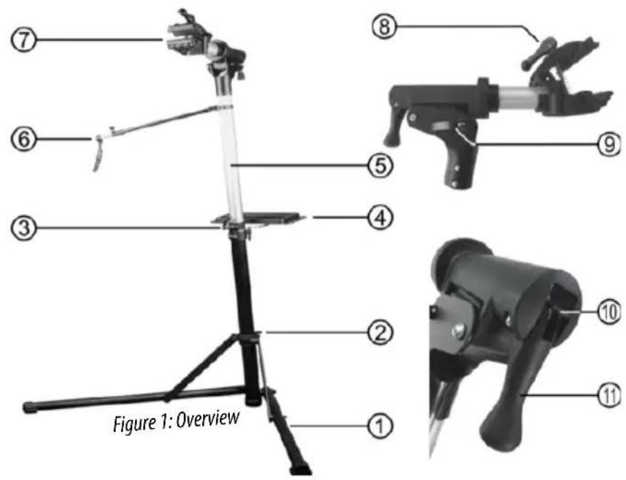
5.1 Overview
5.2 Setting up the bicycle assembly rack 6
5.3 Securing a bicycle
5.4 Attaching the handlebar bracket
5.5 Folding up the bicycle assembly rack - Maintenance and care
- Notes regarding environmental protection
- Contact information
WARNING

Please read the operating instructions carefully prior to use and observe all safety instructions!
Not observing such may lead to personal injury, damage to the device or to your property!
Store the original packaging, the receipt and these instructions so that they may be consulted at a later date! When passing on the product, please include these operating instructions as well.
Please check the contents of package for integrity and completeness prior to use!
1. Proper use of the product
The assembly rack is designed only for maintenance or assembly work, or for repairs to the bicycle.
This device is not designed to be used by children or persons with limited mental abilities or without experience and/or lack of required specialist knowledge. Keep children away from the device.
The device is not designated for commercial use.
Use according to the intended purpose also includes the observance of all information in these operating instructions, particularly the observance of the safety notes. Any other utilisation is considered to be contrary to the intended purpose and may lead to material damage or personal injuries. EAL GmbH assumes no liability for damage resulting from improper use.
2. Scope of delivery
1 x Bicycle assembly rack
1 x Tool shelf
1 x Handlebar bracket
1 x Operating instructions
3. Specifications
Maximum payload: 30 kg
Weight: 4.5 kg
Maximum working height: 1.60 m
Maximum frame height: 80 mm
4. Safety instructions

- The warning triangle indicates all instructions which are important for safety.
• Always follow these otherwise you could injure yourself or damage the device.
• Children may not play with the device. - Cleaning and user maintenance may not be carried out by children without supervision.
- Do not treat packaging material carelessly. This may become a dangerous plaything for a child!
- Only use this product for its designated purpose!
-
Do not manipulate or disassemble the bicycle assembly rack!
-
For your own safety, only use accessories and spare parts that are stated in these instructions or that are recommended by the manufacturer!
• Always set the bicycle assembly rack up on a firm, even and flat surface. There is a risk of tipping and injuries. - Never load the bicycle assembly rack with more than 30 kg. There is a risk of injuries or damage to objects.
- Prior to each use, check the bicycle assembly rack for damages, such as cracks or deformation. A damaged assembly rack may not be used.
- Never sit on a bicycle that is clamped into an assembly rack.
- When clamping the bicycle frame into place, pay attention to ensure that none of the cords or electrical lines are damaged.
- When clamping the bicycle frame, pay attention to ensure that delicate bicycles frames, such as those made from carbon or thin-walled aluminium, are not damaged.
- If possible, always clamp the bicycle frame via its centre of gravity. There is a risk of tipping and injuries.
5. Operating instructions
5.1 Overview
1 Base foot
2 Quick clamping base foot
3 Quick clamping telescopic pipe
4 Tool shelf
5 Upper telescopic pipe
6 Handlebar bracket
7 Frame clamps
8 Quick closure frame clamps
9 Locking mechanism for folding joint
10 Unlocking mechanism for rotating mechanism
11 Locking lever for rotating mechanism
text_image
Figure 1: OverviewThe bicycle assembly rack is, for the most part, already pre-assembled. You only need to mount the tool shelf and handlebar bracket.
5.2 Setting up the bicycle assembly rack
Fold the base foot out (Position 1 in the Overview). Secure the base foot in position using the quick clamp (Position 2 in the Overview). To do this, fold the lever of the quick clamp up to the pipe. If this is not secure enough, fold the lever back and rotate it clockwise 1 or 2 turns on the thread. Then fold the lever of the quick clamp back up to the pipe. Repeat this procedure until the base foot is sufficiently secured.
Pull the upper telescopic pipe out (Position 5 in the Overview). Secure the telescopic pipe with the quick clamp (Position 3 in the Overview) by folding the lever up to the pipe. If this is not secure enough, fold the lever back and rotate it clockwise 1 or 2 turns on the thread. Then fold the lever of the quick clamp back up to the pipe. Repeat this procedure until the upper telescopic pipe is sufficiently secured.
Fold the head, with the frame clamp (Position 7 in the Overview) into the working position, Figure 2. Secure the head by pushing the lever of the locking mechanism into place (Position 9 in the Overview). If this is not secure enough, fold the lever back and rotate it clockwise 1 or 2 turns on the thread. Then fold the lever back up to the pipe. Repeat this procedure until the head is sufficiently secured with the frame clamp.
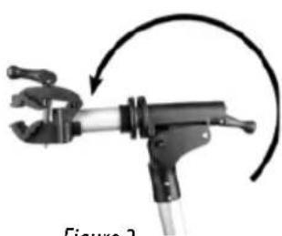
natural_image
Mechanical clamp assembly with curved arrow indicating rotation (no text or symbols)Figure 2
Fit the tool shelf (Position 4 in the Overview) into the bracket on the lower telescopic pipe.
5.3 Securing a bicycle
First open the frame clamp (Position 7 in the Overview) by folding up the lever of the quick closure (Position 8 in the Overview) and rotating anti-clockwise. Open the frame clamp just enough to enable the pipe of the bicycle frame to be inserted between the clamping jaws. If the frame clamp is opened too wide, it is not possible to secure the bicycle firmly by closing the quick closure lever. You may need a few attempts to work out how to set the frame clamp before you tension the bicycle in the assembly rack.

There is a risk of injuries if the bicycle falls out of the frame clamp.

If possible, have a second person to help you tension a bicycle in the assembly rack.
If possible, the bicycle should be placed in the assembly rack in such a way that the frame clamp is positioned over the centre of gravity of the bicycle. Now place the bicycle in the frame clamp and close the quick closure. Pay attention to ensure that none of the brake cables or electrical lines are trapped and damaged. Check to ensure that the assembly rack is safely positioned.
If you wish to tension the bicycle in a different position, or for example, by the saddle pipe, it is possible to rotate the frame clamp appropriately. To do this, release the locking mechanism from the rotating mechanism by pushing the small lever (Position 10 in the Overview) up and then folding the locking lever (Position 11 in the Overview) up. The teeth of the rotating mechanism are released, Figure 3.
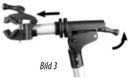
natural_image
Mechanical clamp assembly labeled 'Bild 3' with directional arrows indicating motion (no text beyond label)
CAUTION: Hold the bicycle securely before opening the teeth. The bicycle may suddenly tilt into another position. There is a risk of injury.
Set the frame clamp to the desired angle and push the locking lever back down again. Make sure that the teeth mesh cleanly again.
5.4 Attaching the handlebar bracket
In order to be able to conveniently work on your bicycle, secure the handlebar bracket (Position 6 in the Overview) with one end on the upper telescopic pipe. Undo the plastic screw on the handlebar bracket to adjust to the appropriate length. Secure the other end to the handlebar or front wheel. Tighten the plastic screw up again. The front wheel is now secured and twisting is prevented.
5.5 Folding up the bicycle assembly rack
In order to fold up the bicycle assembly rack, carry out the steps described in section 5.2 in reverse order.
6. Maintenance and care
Clean the bicycle assembly rack with a mild cleaning agent, with warm water and/or a soft cloth. Do not use solvents or similar cleaning agents since these can damage the bicycle assembly rack. All adjusting elements must be kept free from oil and grease.
Store the bicycle assembly rack in a dry location. Protect the assembly rack from direct sunlight. Store the assembly rack out of the reach of children, and securely locked.
7. Notes regarding environmental protection
Dispose of the bicycle assembly rack in accordance with the laws and conditions in your country.
8. Contact information
EAL GmbH
natural_image
Mechanical clamp tool with curved arrow indicating rotation (no text or symbols)Figure 2
natural_image
Mechanical clamp device labeled Figure 3, showing mechanical components and motion arrows (no text or symbols on the device itself)
natural_image
Mechanical clamp tool with curved arrow indicating rotation (no text or symbols)natural_image
Mechanical clamp device with directional arrows indicating motion (no text or symbols on the device itself)
natural_image
Mechanical clamp tool with curved arrow indicating rotation (no text or symbols on the diagram itself)natural_image
Mechanical clamp device with directional arrows indicating movement (no text or symbols on the device itself)