
K-SMS 1600-255 DB - Saw KAWASAKI - Free user manual and instructions
Find the device manual for free K-SMS 1600-255 DB KAWASAKI in PDF.
User questions about K-SMS 1600-255 DB KAWASAKI
0 question about this device. Answer the ones you know or ask your own.
Ask a new question about this device
Download the instructions for your Saw in PDF format for free! Find your manual K-SMS 1600-255 DB - KAWASAKI and take your electronic device back in hand. On this page are published all the documents necessary for the use of your device. K-SMS 1600-255 DB by KAWASAKI.
USER MANUAL K-SMS 1600-255 DB KAWASAKI
Translation of the original instructions Sliding mitre saw
natural_image
Close-up of a person using a power tool, no visible text or symbols on the device itself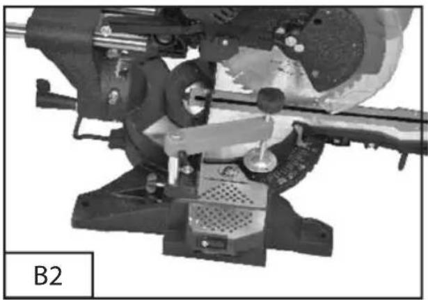
natural_image
Mechanical assembly diagram showing a cutting machine with rotating components and a base mount (no text or symbols visible)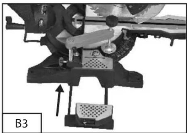
natural_image
Mechanical assembly diagram showing a lever mechanism with a labeled component B3 (no readable text or symbols)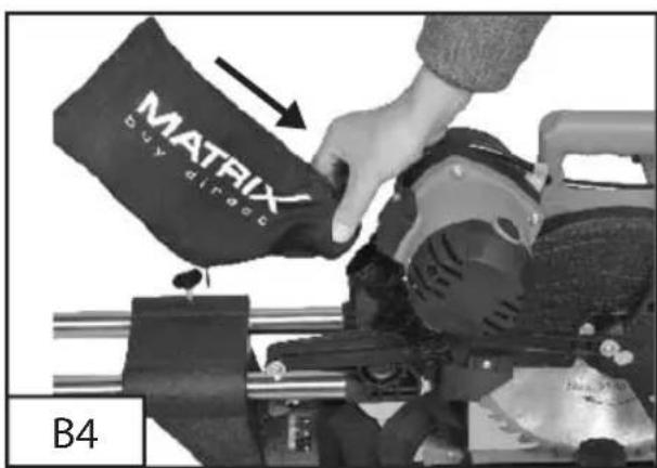
natural_image
Close-up of a mechanical device with visible gears and a labeled component 'B5' (no readable text or symbols beyond label)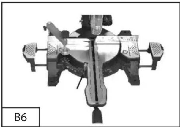
natural_image
Mechanical assembly diagram showing a central component with multiple arms and mounting brackets (no text or symbols)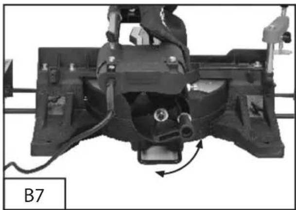
natural_image
Mechanical assembly diagram showing a motor or conveyor system with rotating components and wiring (no text or symbols visible)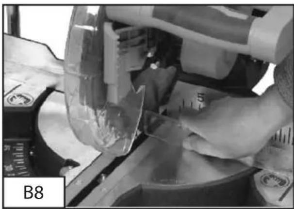
natural_image
Close-up of hands using a tool to cut a transparent object into a mechanical component (no visible text or symbols)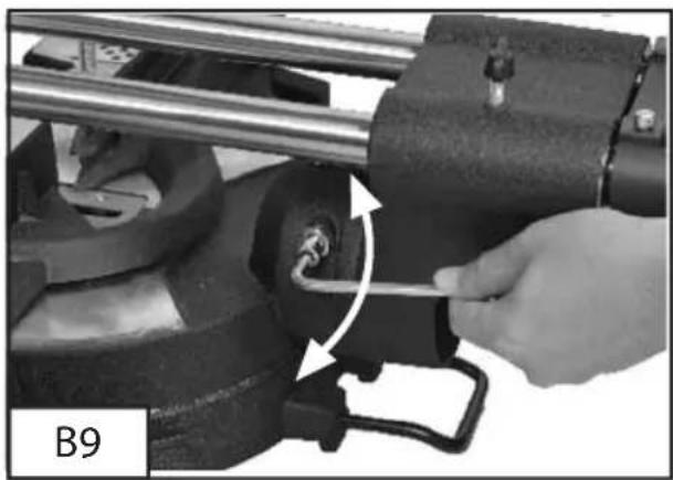
natural_image
Close-up of a hand using a tool to adjust or install a mechanical component, no visible text or symbols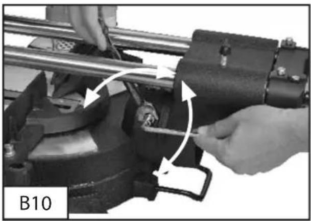
natural_image
Close-up of hands operating a mechanical assembly with rotating components (no visible text or symbols)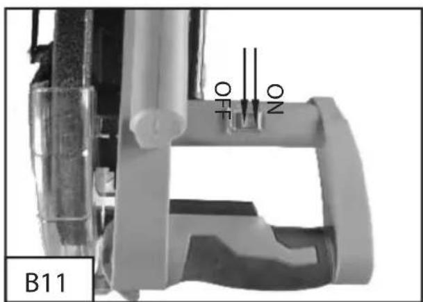
natural_image
Mechanical assembly diagram showing a vehicle suspension system with no visible text or symbols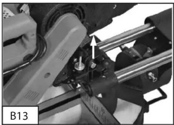
natural_image
Mechanical assembly diagram showing a vehicle suspension system with rotating components and a directional arrow (no text or symbols)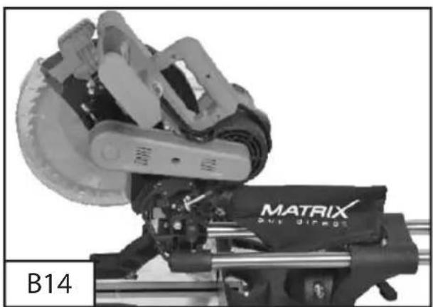
natural_image
Mechanical assembly with a multi-barrel clamp and a Matrix-branded base, labeled B14 (no readable text or symbols beyond branding)
natural_image
Mechanical assembly diagram showing a vehicle suspension system with rotating components and a labeled section B15 (no readable text or symbols)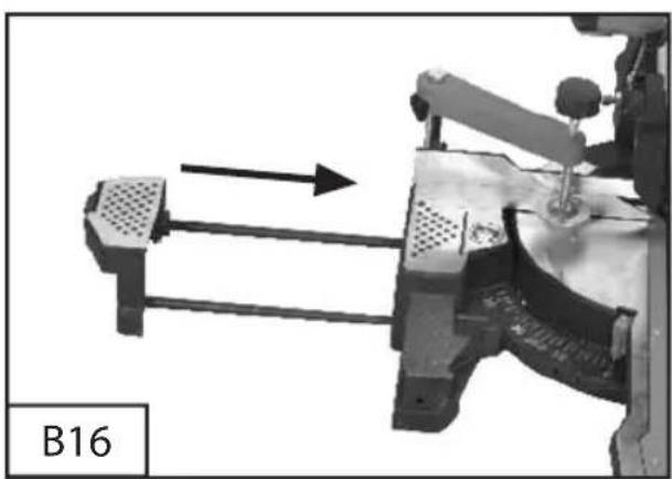
natural_image
Mechanical assembly diagram showing a lever mechanism with directional arrow (no text or symbols)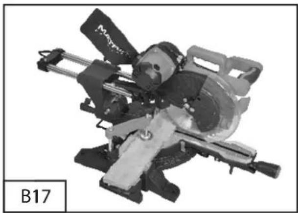
natural_image
Mechanical tool with cutaway view and labeled part B17 (no readable text or symbols on the device itself)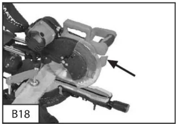
natural_image
Close-up of a cutaway view of a mechanical tool with a cutting board and blade, labeled B18 (no text or symbols on the diagram itself)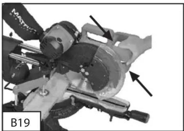
natural_image
Close-up of a mechanical device with visible components and arrows indicating features (no readable text or symbols)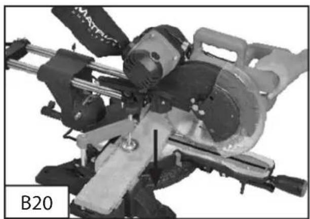
natural_image
Close-up of a mechanical cutting tool with visible blades and levers (no text or symbols)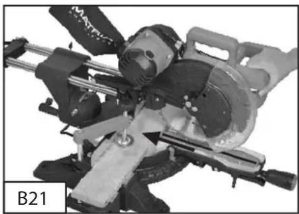
natural_image
Close-up of a mechanical cutting tool with visible blades and a labeled part B21 (no text or symbols on the tool itself)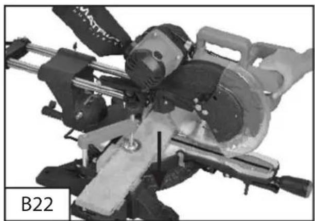
natural_image
Mechanical tool with cutaway view showing blade and blade assembly (no text or symbols visible)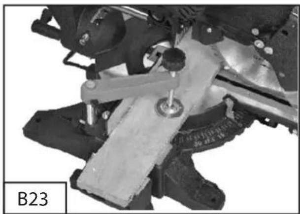
natural_image
Mechanical assembly diagram showing a lever mechanism with a base plate and mounting bracket (no text or symbols visible)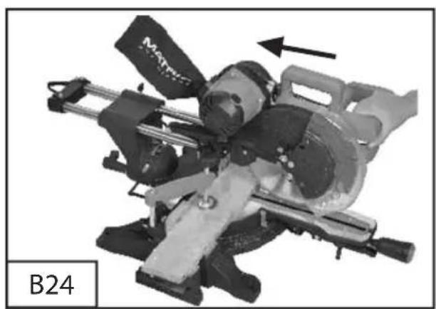
natural_image
Mechanical assembly with a cutting tool and directional arrow, labeled B24 (no readable text or symbols beyond label)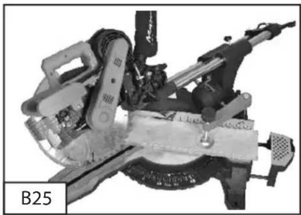
natural_image
Mechanical assembly with mechanical components and a labeled part B25 (no readable text or symbols)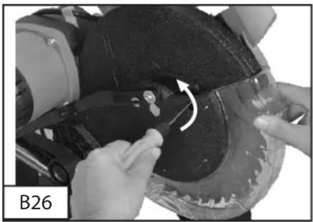
natural_image
Close-up of hands installing or adjusting a mechanical component with an arrow indicating rotation (no text or symbols visible)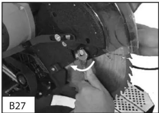
natural_image
Close-up of a mechanical assembly with a curved arrow indicating a component (no visible text or symbols)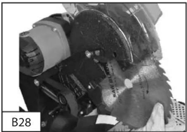
natural_image
Close-up of a mechanical component with visible teeth and a labeled part 'B28' (no readable text or symbols on the main subject)D
Inhaltsverzeichnis
- Description of symbols
- Machine components
- Accessories
- Machine components (A1/4)
- Proper usage
- General Safety instructions
- Special safety instructions
- Before starting
- Transport
- Assembly
- Maintenance and care
- Technical data
-
Environmental protection
-
Working with the crosscut and mitre saw
1. Safety instructions and warnings
The equipment complies with the safety regulations required for electrical equipment. Read through the instructions for use before starting up the equipment.
Improper use can lead to personal injury and property damage. Persons, who are not familiar with the instructions, may not operate the equipment.
Keep the instructions for use in safe custody. Children and youths are not permitted to operate the equipment.
2. Description of symbols
Pay attention to all the signs and symbols shown in these instructions and on your tool. Make a note of these signs and symbols. If you interpret the signs and symbols correctly, your work with the machine will be safer and better.

Important.
Do not look straight into the laser.
Laser class II

Important.

Read the instructions for use before starting the machine.

Wear safety goggles.

Wear ear protection.

Wear good quality, strong gloves.

Always use breathing apparatus when machining materials which generate dust.
3. Accessories
This CROSSCUT AND MITRE SAW WITH DRAG FUNCTION is supplied with the following accessories:
- Chip bag
- Clamping device
- Side support (2x)
- Hexagonal wrench
- Saw blade with 36 teeth (fitted)
4. Machine components (A1-4)
- Laser
- Laser cover
- Laser adjustment
- Sawing arm
- Release knob
- Control lever
-
Carry handle
-
ON/OFF switch for the laser light
GB
-
Top safety hood (fixed)
-
Clamping device
-
Lock for clamping device
-
Moving safety hood
-
Safety hood control arm
-
Cover for saw blade screws
-
Chip bag
-
Vertical angle lock
-
Vertical angle scale
-
Fence
-
Hexagonal wrench
-
Mitre bench
-
Mitre scale
-
Bench insert (slotted plate)
-
ON/OFF switch for machine
-
Mitre angle lock
-
Spindle locking button
-
Connection for dust extractor
-
Guide rails
-
Drag lock
-
Setting screw for cutting depth
-
Depth stop
-
Lock nut
-
Setting screw for sawing head angle
-
Stopper for 90° lock
-
Release lever for saw blade guard
-
Side supports (2x)
-
Positioning holes for side supports
(2 pairs)
5. Proper usage
This machine is designed for crosscutting wood and plastic in sizes commensurate with the machine size.
It is not suitable for cutting firewood.
Use only saw blades which are suitable for the machine. Do not use cutting discs.
The manufacture assumes no liability whatsoever for improper use or if the machine has been tampered with.
Give equal attention to the safety instructions, assembly and operating instructions as well as prevailing accident preventions regulations.
6. General safety instructions
- Keep your work area clean and well lit to prevent accidents.
- Don't use electric devices close to flammable liquids or gasses or in wet or damp environments. If you fail to observe this, there is a danger of fire or explosion.
- Never leave the device running unattended.
- Never use the device when you are tired or lack concentration or if your reactions are impaired due to consumption of alcohol or medication. Lack of attention can lead to serious injury.
- Keep the tools clean and in good working order in order to be able to work better and safer.
- Don't wear bulky clothing or jewellery.
- Make sure you can stand stably and have shoes that won't slip.
- Use a head cover if you have long hair.
- Loose clothing, jewellery, and long hair can become entangled in moving parts.
- Always wear safety goggles.
- Wear a dust mask when working with materials that produce dust.
- Wear ear protection if a lot of noise is produced.
- Persons using the machines must not be distracted.
This could cause one to lose control over the tool.
- Don't use any device that has a faulty on/off switch. An electric tool that can no longer be switched on or off is dangerous and must be repaired.
• Always switch the device on before coming into contact with the material.
- Remove keys and adjusting tools before switching on the device.
- Never overload the machine. If the speed drops, unload the machine or switch it off. You will work safer and better with the appropriate electric tool in a specific area of application.
- Stop the workpiece from turning, for example with a clamping device or a vice. Don't work on any workpiece that is too small to clamp in place. If you hold the workpiece with your hand, then you can't operate the tool safely.
- Keep electric tools out of the reach of children.
- Only use accessories recommended by the manufacturer.
- The mains voltage must correspond to the information on the machine's type plate.
- Avoid body contact to grounded elements, e.g. pipes, radiators, stoves, and refrigerators, to prevent an electric shock.
- Never carry the device by the cable. Only pull the cable from the receptacle with the plug. Protect the cable from oil, heat, and sharp edges. Damaged cables can cause an electric shock.
- Check the device and power cable for damage before starting work.
- When plugging in the power plug, make sure that the operating switch is not located in position.
- Only use approved extension cables when using the device outside.
- When using a cable drum, unwind it entirely in order to prevent the cable from heating up. The
minimum wire gauge is 1.5 mm ^4 .
- When working outside, the receptacle must be equipped with a residual current circuit-breaker.
- Pull the plug when you are not using the device or making adjustments.
- Always guide the cable away from the back of the tool.
7. Special safety instructions
- Never use the crosscut mitre saw for cutting materials other than those specified by the manufacturer.
- Only use the saw if the guards are in the correct positions and if the saw is in good condition and has been serviced correctly.
- Ensure that the equipment for swinging the arm on mitre saws is securely fastened.
- The floor around the machine must be flat, clean and clear of loose particles such as chips and off-cuts.
- Ensure that there is reasonable lighting in the workplace or room.
- The operator must have received adequate training in the use, setting and operation of the machine.
- Ensure that you only use spacing discs and spindle rings which are suitable for the purpose specified by the manufacturer.
- The laser must not be replaced by a laser of a different type. Repairs may only be carried out by the manufacturer of the laser or an authorised representative.
- Damaged or deformed saw blades must not be used.
GB
- Replace worn table inserts.
- Use only saw blades which are recommended by the manufacturer and comply with EN 847-1.
- Do not use saw blades made of high speed steel.
- The crosscut mitre saw must be connected to a dust extraction system for sawing wood.
• Always position the workpiece securely on the machine surface to prevent the workpiece moving. - Use an additional support for long workpieces (for example a table or saw stool) to prevent the machine from tipping over. Do not ask other people to hold the workpiece.
- Place the machine on a strong, flat working area before use.
- Check whether the moving parts of the machine are in perfect working order and that no parts are damaged.
- Check the direction of rotation of the motor and saw blade.
- Replace defective saw blades immediately.
- Keep your hands, fingers and arms away from the rotating saw blade.
- Do not reach behind the stop rail near the saw blade, the distance between your hand and the rotating saw blade is too small for this.
- Only saw one workpiece at a time. Workpieces placed on top of each other or side by side cannot be clamped correctly and they may jam the saw blade or move relative to each other.
- Keep the cutting track free of obstacles both at the top and bottom.
- Do not saw workpieces which contain nails or
similar foreign bodies.
• Always work to the side of the saw blade.
- Ensure that the off-cuts can be removed to the side of the saw blade so that they do not become caught in the saw blade.
• Always switch off the machine and pull the plug to rectify problems or remove jammed pieces of wood. Only then can you remove the jammed workpiece.
- Do not overload the machine so that it comes to a standstill.
- Protect the saw blade from impacts and shocks. Do not exert any lateral pressure on it.
- Caution. The saw blade will continue to turn after the machine has been switched off.
- The saw blade will become very hot during use. Do not touch it until it has cooled down.
- Select the appropriate saw blade for the material that you wish to saw.
8. Before starting
- Assemble the machine in a stable position, in other works on a workbench, a sub-frame or the like. Secure it if you wish to use the machine on a stationary basis.
- Before starting the machine, check that all covers and safety equipment are correctly fitted.
• The saw blade must be able to run freely. - Check all the moving parts to ensure that they move easily.
- Before you connect the machine, check the information on the rating plate against the mains data.
9. Transport
Only lift the mitre saw if the sawing arm is locked in its lowered position, the saw is switched off and the mains plus has been pulled.
The saw may only be lifted using the carry handle (8) or the external cast parts. Do not hold the saw by the safety hood or control lever (7) to lift it. (B1)
10. Assembly
ASSEMBLY ON THE WORKBENCH
There are holes on the foot of the saw to make it easy to install it on a workbench.
Secure the saw on a straight, flat workbench. (B2) Insert suitable screws (not supplied) through the installation holes in the foot of the saw for this purpose.
NOTE: If necessary you can also secure the saw to a piece of plywood with a minimum thickness of 13 mm. The plywood may be secured on a working sarea using clamps or transported to another workplace and secured there.
CAUTION. The fastening surface must be flat. An uneven surface may result in the saw blade jamming or imprecise cutting.
FITTING THE SIDE SUPPORT (B3)
Place the two guide rods into the side supports and secure them.
The chip bag (15) will fit on the connect for the extractor (26). To ensure efficient operation, you should empty the chip bag when it is half full. (B4)
ADJUST BENCH PERPENDICULAR TO THE SAW BLADE
Pull the mains cable out of the socket.
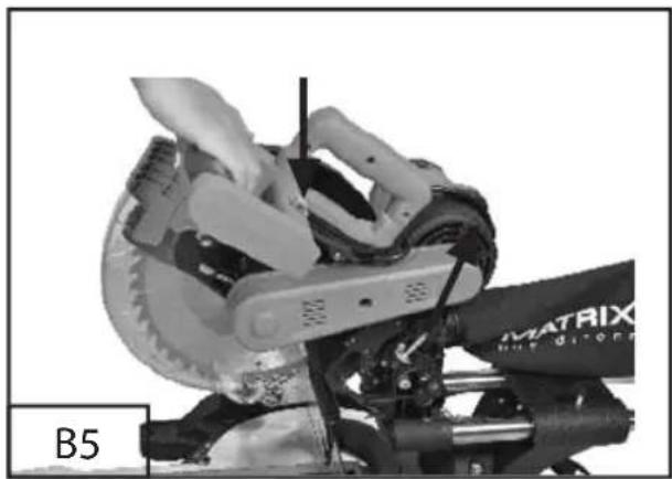
Press the sawing arm (5) into the lowered position and press the release knob (6) to lock the sawing arm in its transport position. (B5)
Release the mitre angle lock (24).
GB
Turn the mitre bench (20) until the pointer points to 0^ . (B6)
Tighten the mitre angle lock (24).
Release the vertical angle lock (16) and set the sawing arm (5) to a vertical angle of 0^ (in other words the saw blade is at an angle of 90^ to the mitre bench). Tighten the vertical angle lock (16). (B7)
Hold an angle bracket against the bench (20) and the flat part of the saw blade. (B8)
NOTE: The angle bracket must touch the flat part of the saw blade, not its teeth.
Turn the saw blade by hand and check the correct alignment between the saw blade and the bench at several points.
The edge of the angle bracket should run parallel to the saw blade.
If the saw blade is not parallel to the angle bracket, make the adjustment as follows:
- Undo the lock nuts on the sawing head vertical angle (32) using a wrench or an adjustable wrench. (B9)
- Undo the lock nut which is secured by the 0^ vertical angle setting screw (33) using a wrench or an adjustable wrench. Release the vertical angle lock (16). (B10)
- Adjust the screw on the sawing head vertical angle (32) with a screwdriver by turning it clockwise and anti-clockwise so that the saw blade is on the 90^ angle bracket.
- Undo the screw which holds the pointer on the vertical angle scale (17) and set the pointer so that it points to zero. Tighten the screw again.

- Tighten the vertical angle lock (16) and the lock nut to secure the sawing head vertical angle (32).
NOTE: The above procedure can also be used to check the angle of the saw blade relative to the bench for a vertical angle of 45^ . The 45^ vertical angle setting screw (32) is on the other side of the sawing arm.
SWITCHING ON THE LASER LINE
Switch on the ON/OFF switch for the laser light (2). (B11)
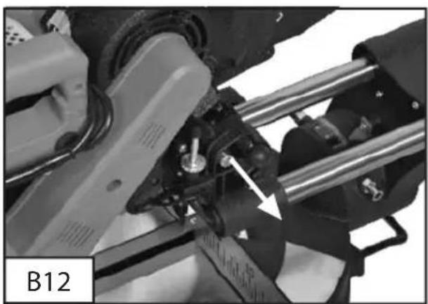
ADJUSTING THE CUTTING DEPTH
Release the swing head lock (6) by pulling it. The sawing head will swing upwards. (B12)
Set the required cutting depth using the setting screw (29). (B13)
Secure the stop screw using the lock nut (31). (B14)
SIDE SUPPORTS
Long pieces of wood can be supported using the side supports (35). (B16)
There are two positioning holes (36) on each side of the bench for the side supports.
The side supports must be completely locked in position before a workpiece is placed on them.
11. Working with the crosscut and mitre saw
WARNINGS
- Do not look directly into the laser beam. Never direct the laser beam at people or objects other than the workpiece.
-
Do not deliberately point the laser beam at people.
-
Only point the laser beam at insensitive workpieces with a dull surface. Wood or rough surfaces are ideal for this. Shiny, reflective surfaces are not suitable for using a laser since the laser beam could be directed at the user by the reflective surfaces.
- Always switch off the laser when you have finished work at the ON/OFF switch for the laser light (2). Only switch on the laser beam if there is a workpiece on the mitre saw bench.
- Mark the cutting line on the workpiece.
- Adjust the mitre and vertical angle for the cut as required.
NOTE: To make a cut to the left of the saw blade, direct the left laser line along the pencil mark. To make a cut to the right of the saw blade, direct the right laser line along the pencil mark. (B17)
1. NORMAL SAWING
1) Insert the mains plug into the socket. Switch on the ON/OFF switch for the laser light (2). (B11)
2) Clamp the workpiece and align the saw blade along the mark on the workpiece using the laser line and then switch on the motor.
3) Press the release switch (34). (B18)
4) Lower the sawing arm.
5) Press the ON/OFF switch (23). (B19)
6) When the saw blade has reached its maximum speed (after around 2 seconds), lower it slowly through the workpiece. (B20)
Press the sawing head backwards away from you as far as possible. (B21)
Switch off the ON/OFF switch for the laser light (2) after you have completed the cut.
7) Raise the sawing arm (5) and remove the saw dust on the laser using a soft brush.
NOTE: Wear safety goggles and breathing apparatus to remove the saw dust.
2. CROSS CUTS (WITHOUT DRAG FUNCTION) (B22)
The drag function is not required for sawing narrow pieces of wood. Always make sure in these cases that the drag lock (28) is secure so that the sawing arm cannot slide backwards and forwards.
1) A cross cut is made across the grain of the workpiece.
A 90° cross cut is carried out by setting the mitre bench to 0°. For mitre cross cuts the bench must be set to an angle other than zero.
2) Release the mitre angle lock (24).
Turn the mitre bench (21) until the pointer points to the required angle.
Tighten the mitre angle lock (24) again. WARNING. The mitre angle lock must be tightened before the cut is carried out. Otherwise the bench can move during sawing which can result in serious injuries.
Place the workpiece flat on the bench with one edge securely against the guide rail (18). If the board is curved place the side curving outwards against the guide rail (18). If the side which curves inwards is placed against the guide rail, the board may snap and jam the saw blade.
3) When sawing long boards, support the end of the board level with the saw bench using the side supports (35), a roller frame or a worktop. 4) If possible use the clamping device (10) to clamp the workpiece securely. The clamping device (10) can be removed after the lock (11) has been undone and then fitted
on the other side of the bench. When using the clamping device ensure that its lock is secure. Before you switch on the saw carry out a dry run of the sawing process to ensure that no problems occur. (B23)
5) Hold the control lever (7) securely and press the release switch (23). Wait until the saw blade has reached maximum speed.
Press the release switch (34) and slowly lower the saw blade into the workpiece and through the workpiece.
Let go of the release switch (23), wait until the saw blade has reached a standstill and only raise the saw blade again at this point. Do not remove the workpiece until the saw blade has reached a standstill.
3. CROSS CUTS (WITH DRAG FUNCTION) (B24)
For sawing wide workpieces the drag lock (28) must first be released.
Pull out the locking knob (6), raise the sawing arm (5) to its highest point and slide it towards you. Press the release switch (34) and slowly lower the saw blade on to the workpiece. Move the sawing head away from you as far as possible as you do so.
Press the release switch (34) and slowly lower the saw blade on to the workpiece.
Slide the saw away from you as you do so.
Let go of the release switch (23), wait until the saw blade has reached a standstill and only raise the saw blade again at this point. Do not remove the workpiece until the saw has reached a complete standstill.
4. VERTICAL ANGLE CUTS (B25)
A vertical angle cut is carried out across the grain of the workpiece with the saw blade at a certain
GB
angle to the guide rail and the mitre bench. The mitre bench must be set to 0^ and the saw blade must be set to an angle between 0^ and 45^ . Use the drag function for sawing wide workpieces.
Repeat steps 28 and 29 in point 3 Cross cuts (with drag function).
Release the vertical angle lock (16) and move the sawing arm (5) to the left to the required vertical angle (between 0° and 45°). Tighten the vertical angle lock (16).
Repeat steps 30 and 31 from point 15 Adjusting the cutting depth.
5. COMBINED MITRE CUTS
The mitre angle and the vertical angle must both be set for combined mitre cuts.
This process is used, for example, to make picture frames, for cutting strips and for making crates using angled side walls and also for roof trusses. Always test the cut first using a piece of waste wood before you cut the actual material.
Use the drag function for sawing wide workpieces.
12. Maintenance and care
CAUTION.
- Never attempt to use a saw blade which exceeds the maximum specified size for the saw. The saw blade could come into contact with the safety hood.
- Never use saw blades which are excessively thick which will prevent contact between the external saw blade washer and the flattened parts of the spindle. This means that the saw blade cannot be secured correctly to the spindle with the saw blade screw.
- Do not use the saw to cut metal or masonry.
- Please note that the spacers and spindle rings which may be required are suitable for the spindle and the saw blade you wish to use.
- The mains cable must be disconnected from the mains supply.
1. CHANGE SAW BLADES
1) Press the control lever (7) downwards and pull the release knob (6) to release the sawing arm (5). The release knob can be locked in the released position by turning it. Move the sawing arm (5) into its highest position.
2) Remove the Philips screw which secures the saw blade screw cover (14). (B26)
3) Pull the moving safety hood (12) downwards and then swing it upwards together with the saw blade screw cover (14).
4) If the moving safety hood (12) is above the top, fixed safety hood (9), the saw blade screw is accessible.
5) Hold the moving safety hood (12) in its top position and press the spindle locking button (25). Turn the saw blade until the spindle locks.
6) Remove the saw blade screw using the hexagonal wrench (19). (Turn the wrench clockwise since the saw blade screw has a left-handed thread).(B27)
7) Remove the external washer and the saw blade.
Apply a drop of oil to the internal and external washers at the places in which it is in contact with the saw blade.
Secure the new saw blade on the spindle. Ensure that the internal washer is located behind the saw blade.
CAUTION. Always fit the saw blade so that the teeth and the arrows printed on the side of the saw blade point downwards so that the saw blade will rotate in the correct direction. There is also an arrow on the top safety hood to show the direction of rotation of the saw blade. (B28)
8) Fit the external saw blade washer again. Press the spindle locking button (25) and fit the saw blade screw again.
9) Tighten the screw with the hexagonal wrench (19) (turn it anti-clockwise).
Move the moving bottom safety hood (12) and the saw blade screw cover (14) into the correct position and tighten the securing screws. Check whether the safety hood functions correctly and covers the saw blade when the sawing arm is lowered.
Connect the saw to the power supply and start the saw blade to check whether it functions correctly.
2. MAINTENANCE
- Keep the ventilation openings on the machine clean and free of blockages at all times.
- Check regularly whether dust or foreign particles have got into the ventilation grille next to the motor and in the area around the release switch. Remove the accumulated dust with a soft brush. Wear safety goggles when cleaning these areas.
- Grease all moving parts at regular intervals.
- Clean the machine's housing, if necessary, using a soft damp cloth. A mild detergent may be used but never use alcohol, petrol or other aggressive cleaning product.
- Never use discharging agent to clean plastic parts.
CAUTION. Ensure that no water gets into the
machine.
3. GENERAL INSPECTION
Check at regular intervals that all the securing screws a firmly tightened. Pay special attention to the external flange. The screws may come loose over time due to vibration.
Check the machine's mains cable and all the extension cables you use for signs of damage at regular intervals. Have the mains cable replaced by an authorised outlet.
Replace damaged extension cables.
4. LUBRICATION
After extended use the oil in the machine's gearbox must be changed. Contact an authorised outlet for this purpose.
13. Technical data
This machine has double insulation. It has two independent insulations to protect you from electric shocks.
| Voltage: | 230 V ~/50 Hz |
| Rating: | 1600 W, S6 25% 1900 W |
| Idling speed: | 6000 rpm |
| Saw blade: | 255 mm x 30 x 2,8 mm, 36 T |
| Angle of mitre bench: | -45°/0°/+45° |
| 0° x 0°: | 340 mm x 75 mm |
| 0° x 45°: | 340 mm x 45 mm |
| 45° x 0°: | 240 mm x 75 mm |
| 45°x 45°(L): | 240 mm x 45 mm |
| min: | 100 mm x 10 mm |
DETAILS OF NOISE AND VIBRATION DEVELOPMENT
A-rated noise level L_PA : 97,5 dB(A) A-rated noise rating L_WA : 106,8 dB(A) K=3 dB(A)
Vibrations 2.5 m/s^2 K=1.5 m/s^2

Use only the accessories and spare parts recommended by the manufacturer. If the device suffers a failure despite our quality controls and your care, have repair work carried out only by an authorised electrician.
14. Environmental protection
End of life electrical equipment must not be placed in household waste. Please take it to a return point. Find out about your nearest return point from your council or sales outlet.
Sommaire
MONTÁŽ NA PRACOVNÍ STŮL
INFORMATIE M.B.T. LAWAAI- EN TRILLINGSPRODUCTIE
A-geluidsdrukniveau L_PA : 97,5 dB(A) Max. A-geluidsdrukniveau L_WA : 106,8 dB(A) K=3 dB(A)
Trillingen: 2,5 m/s ^4 K=1.5 m/s ^2
GB hereby declares the following conformity under the EU Directive and standards for the following article
This appliance is a quality product. It was designed in compliance with current technical standards and made carefully using normal, good quality materials.
The warranty period is 24 months and commences on the date of purchase, which can be verified by the receipt, invoice or delivery note. During this warranty period all functional errors, which, despite the careful treatment described in our operating manual, are verifiably due to material flaws, will be rectified by our after-sales service staff.
The warranty takes the form that defective parts will be repaired or replaced with perfect parts free of charge at our discretion. Replaced parts will become our property. Repair work or the replacement of individual parts will not extend the warranty period nor will it result in a new warranty period being commenced for the appliance. No separate warranty period will commence for spare parts that may be fitted. We cannot offer a warranty for damage and defects on appliances or their parts caused by the use of excessive force, improper treatment and servicing.
This also applies for failures to comply with the operating manual and the installation of spare and accessory parts that are not included in our range
of products. In the event of interference with or modifications to the appliance by unauthorised persons, the warranty will be rendered void. Damages that are attributable to improper handling, over loading, or natural wear and tear are excluded from the guarantee.
Damages caused by the manufacturer or by a material defect will be corrected at no charge by repair or by providing spare parts. The prerequisite is that the equipment is handed over assembled, and complete with the proof of sale and guarantee.
For a guarantee claim, only use the original packaging.
That way, we can guarantee quick and smooth guarantee processing.
Please send us the appliances post-paid or request a Freeway sticker. Unfortunately we will be unable to accept appliances that are not postpaid. The warranty does not cover parts that are subject to natural wear and tear. If you wish to make a warranty claim, report faults or order spare parts or accessories, please contact the after-sales centre below:
Subject to change without prior notice.
F
GARANTIE
Tradepartner and aftersales office: