USER MANUAL PSFA15 SCHEPPACH
Günzburger Straße 69
D-89335 Ichenhausen
Verehrter Kunde
Homepage: https://www.scheppach.com/de/service
Explanation of the symbols on the product
Symbols are used in this manual to draw your attention to potential hazards. The safety symbols and the accompanying explanations must be fully understood. The warnings themselves will not rectify a hazard and cannot replace proper accident prevention measures.
| Warning - read the instruction manual to reduce the risk of injury. |
| Observe warnings and safety instructions! |
| Danger! Dangerous pressure! Can cause severe injuries or heavy property damage due to the filter tank bursting. |
| Attention: Always switch the pump off before changing the mode. |
| The product complies with the applicable European directives. |
| We have marked points in this operating manual that impact your safety with this symbol. |
Table of contents: Page:
- Introduction 23
- Device description 23
- Scope of delivery 23
- Proper use 23
- General safety information 24
- Residual risks 25
- Technical data 26
- Unpacking 26
- Assembly 26
- Assembly 26
- Start up 27
- Electrical connection 28
- Cleaning 29
- Storage 29
- Maintenance 29
- Disposal and recycling 30
- Troubleshooting 31
1. Introduction
Manufacturer:
Scheppach GmbH
Günzburger Straße 69
D-89335 Ichenhausen
Dear Customer
We hope your new tool brings you much enjoyment and success.
Note:
In accordance with the applicable product liability laws, the manufacturer of this device assumes no liability for damage to the device or caused by the device arising from:
- Improper handling,
Non-compliance with the operating manual,
- Repairs carried out by third parties, unauthorised specialists.
- Installing and replacing non-original spare parts
Application other than specified
- Failure of the electrical system in the event of the electrical regulations and VDE provisions 0100, DIN 13 / VDE0113 not being observed
Please consider:
Read through the complete text in the operating manual before installing and commissioning the device.
The operating manual is intended to help the user to become familiar with the machine and take advantage of its application possibilities in accordance with the recommendations.
The operating manual includes important instructions for safe, proper and economic operation of the device, for avoiding danger, for minimising repair costs and downtimes, and for increasing the reliability and extending the service life of the device.
In addition to the safety instructions in this operating manual, you must also observe the regulations applicable to the operation of the device in your country. Keep the operating manual package with the machine at all times and store it in a plastic cover to protect it from dirt and moisture. They must be read and carefully observed by all operating personnel before starting the work.
The device may only be used by personnel who have been trained to use it and who have been instructed with respect to the associated hazards.
The required minimum age must be observed.
In addition to the safety instructions in this operating manual and the separate regulations of your country, the generally recognised technical rules relating to the operation of such machines must also be observed.
We accept no liability for accidents or damage that occur due to a failure to observe this manual and the safety instructions.
2. Device description (Fig. 1)
- 5-way multi-valve
- Disposal outlet
- Clamping ring
- O-seal ring
- Filter tank
-
- Drain screw
- Suction connection
-
- Base plate
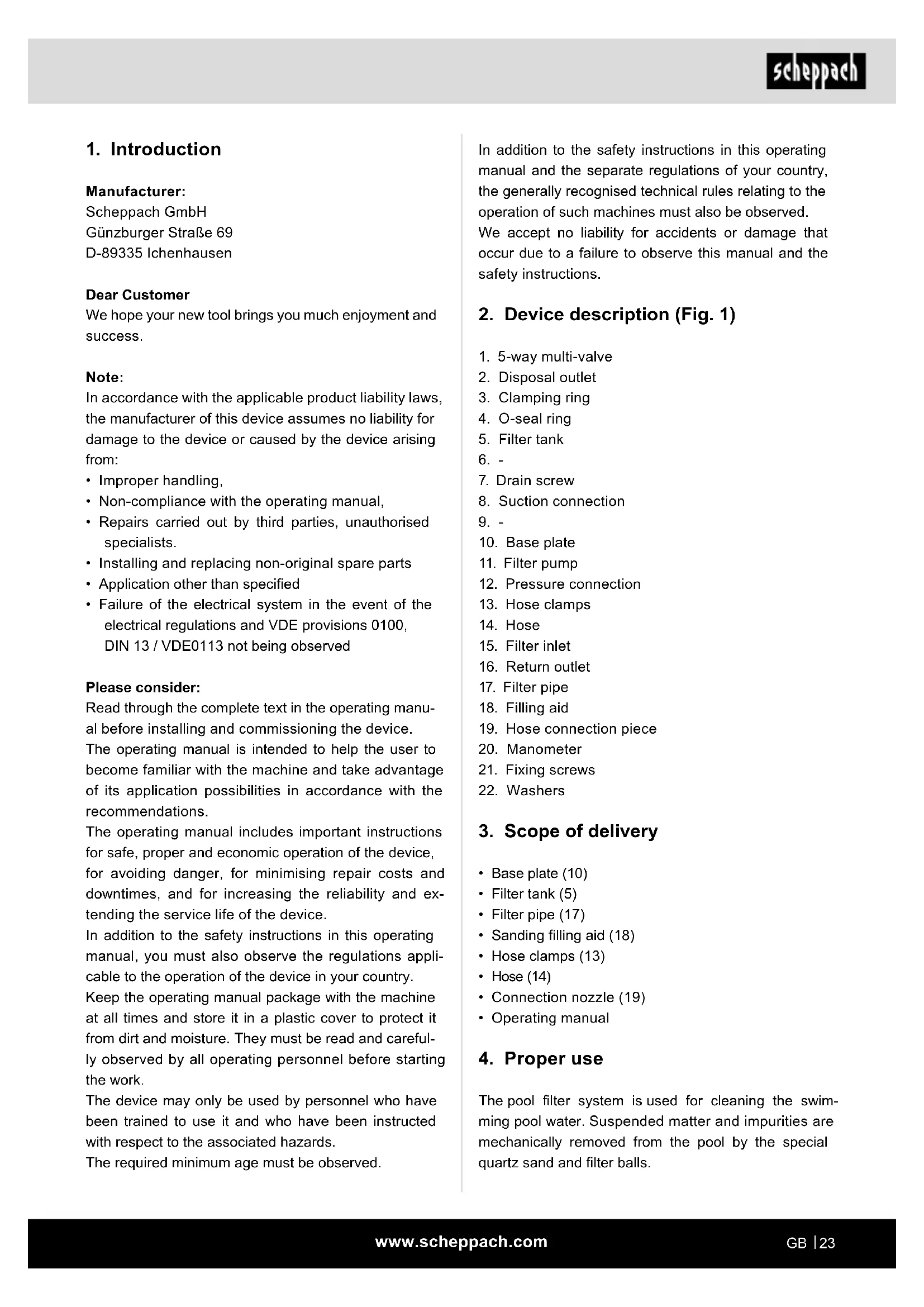
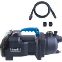
- Filter pump
- Pressure connection
- Hose clamps
- Hose
- Filter inlet
- Return outlet
- Filter pipe
- Filling aid
- Hose connection piece
- Manometer
- Fixing screws
- Washers
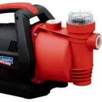
3. Scope of delivery
- Base plate (10)
- Filter tank (5)
Filter pipe (17)
- Sanding filling aid (18)
- Hose clamps (13)
Hose (14)
- Connection nozzle (19)
- Operating manual
4. Proper use
The pool filter system is used for cleaning the swimming pool water. Suspended matter and impurities are mechanically removed from the pool by the special quartz sand and filter balls.
The machine may only be used in the intended manner. Any use beyond this is improper. The user/operator, not the manufacturer, is responsible for damages or injuries of any type resulting from this.
An element of the intended use is also the observance of the safety instructions, as well as the assembly instructions and operating information in the operating manual.
Persons who operate and maintain the machine must be familiar with it and must be informed about potential dangers.
In addition, the applicable accident prevention regulations must be strictly observed.
Other general occupational health and safety-related rules and regulations must be observed.
The liability of the manufacturer and resulting damages are excluded in the event of modifications of the machine.
Area of application
- For filtering swimming pools
For pumping clear water (fresh water),
- The maximum temperature of the pumped liquid must not exceed +43^ .
- This pool filter system must not be used to pump flammable, gaseous or explosive liquids.
- The pumping of aggressive liquids (acids, lyes, silo seepage juice etc.), as well as liquids with abrasive (sanding) materials (sand) must also be avoided.
The machine may only be operated with original parts and original accessories from the manufacturer.
The safety, operating and maintenance specifications of the manufacturer, as well as the dimensions specified in the technical data, must be observed.
Please observe that our equipment was not designed with the intention of use for commercial or industrial purposes. We assume no guarantee if the equipment is used in commercial or industrial applications, or for equivalent work.
The device is intended for use by adults. Children over the age of 16 may use the tool except under supervision. The manufacturer is not liable for damage caused by an improper use or incorrect operation of this device.
WARNING! Read all safety information, instructions, illustrations and technical data for this electric tool.
Failure to follow all instructions listed below may result in electric shock, fire and/or serious injury.
Save all warnings and instructions for future reference.
Supervise children and people with disabilities.
- Keep children away from the product and all electrical cables.
Children may not play with the Product. Cleaning and servicing must not be carried out by children without supervision.
- This product can be operated by children from 8 years of age and persons with impaired physical, sensory or mental capabilities or with a lack of experience or knowledge, if they are supervised or if they have been trained in the safe use of the device and understand the related hazards.
- The product may only be assembled and disassembled by adults. Cleaning and maintenance must be carried out by an adult (over 18 years) who is aware of the danger of electric shock.
- Unplug the product before it is cleaned, removed, maintained or used for another purpose.
- The product must always be unplugged on rainy days as well as in the event of longer, unattended storage (e.g. holidays).
- The electrical connection should be accessible after the product has been installed.
- Do not bury the power cable. The power cable must be placed so that it cannot be damaged by a lawnmower, hedge trimmer or the like.
- If the connection cable of the product is damaged, it must be replaced by a qualified electrician.
- In order to avoid the risk of an electric shock, do not use an extension cable, timer or the like in order to connect the unit to the power supply. Make sure that there is a socket available in a suitable location.
- Do not put product into operation or pull the connector out of the socket if it is in water or if your hands are wet.
- Set up the product at least 3.5m from the pool.
- The device connector must be more than 4m from the pool at a minimum height of 1.2m . Position this product away from the pool in order to prevent children from climbing onto the pump to get into the pool.
- Do not operate this product if there is anyone in the pool.
- This product may only be used in connection with a degradable pool. Do not use it for built-in pools. A storable pool can be completely dismantled and stored over winter and then set up again in the summer.
- In order to prevent the risk of an accident, never enter the pool if the suction device is loose, broken, kinked, cracked, damaged or missing. Replace the loose, broken, kinked, cracked, damaged or missing suction devices immediately.
- Never play or swim in the vicinity of the suction device. Your body or hair could be sucked in and this could cause permanent injuries or cause you to drown.
- In order the prevent damage to the system and the risk of injury, always switch the pump off before changing the position of the filter valve.
- Never operate this product above the maximum working pressure which is specified on the filter container.
- Dangerous pressure. An unauthorised or improper attachment of the filter container cover can cause the cover to shoot up due to the pressure which can cause serious injury, property damage or death.
- This product may only be used for the purpose described in the operating manual.
Electrical safety instructions
- When operating the product, the power plug must be freely accessible after installation.
-
Before you put your new pool filter system into operation, have it professionally checked:
-
Earthing, connection of the neutral line and residual current circuit breaker must comply with the safety regulations of the power supply companies and function properly.
-
Protect the electrical plug connections from moisture.
If there is a risk of flooding, fit the plug connections in the flood-proof area.
-
Ensure that the mains voltage corresponds to the specifications on the type plate.
- Carry out the electrical installation in accordance with the national regulations.
-
Only connect the product to a socket with a residual current circuit breaker (FI switch) with a rated residual triggering current of up to 30mA ; Fuse at least 6 amps.
-
Before each use, always check the product, cable and plug for damages. Defective cables must not be repaired but replaced with a new ones.
- Have product damages repaired by a specialist.
- If the connection cable for the product is damaged then it must be replaced by the manufacturer or their customer services personnel or by a similarly qualified person, in order to avoid hazards.
- Do not use the cable to pull the plug out of the outlet.
- Protect the cable from heat, oil and sharp edges.
- Do not carry or attach the product by the cable.
- Use only extension cables that are splash-proof and intended for outdoor use. Always unroll a cable drum completely before use. Check the cable for damage.
- Pull out the mains plug before all work on the product, in work breaks and when not in use.
- Mains connection cables shall not have a smaller cross-section than rubber hose lines with the designation H05RN-F 3^*0.75mm^2 . The cable length must be 10m . The conductor core cross-section of the extension cable must be at least 1.5mm^2 .
Warning! This power tool generates an electromagnetic field during operation. This field can impair active or passive medical implants under certain conditions. In order to prevent the risk of serious or deadly injuries, we recommend that persons with medical implants consult with their physician and the manufacturer of the medical implant prior to operating the power tool.
6. Residual risks
The machine has been built according to the state-of-the-art and the recognised technical safety requirements. However, individual residual risks can arise during operation.
- Health hazard due to electrical power, with the use of improper electrical connection cables.
- Furthermore, despite all precautions having been met, some non-obvious residual risks may still remain.
- Residual risks can be minimised if the "Safety information" and the "Proper use" together with the operating manual as a whole are observed.
-
Avoid accidental starting of the machine: the operating button may not be pressed when inserting the plug in an outlet. Use the tool attachment that is recommended in this operating manual. This is how to ensure that your machine provides optimum performance.
-
The pool filter system must not be operated above the permitted operating pressure.
- The pool filter system must not be connected to the domestic water supply (due to overpressure).
7. Technical data
Power supply 220-240 V / 50Hz
| Wattage 225 W |
| Maximum working pressure of the pump | 2.4 bar |
| Effective filter area 0,05 m² |
| Max. flow rate for filter pump | 11280 l/h |
| Greatest delivery height 5 m Hmax |
| Recommended filter medium (not included in the scope of delivery) | Quartz sand (0.45mm-0.55mm)
Grade 20,
Filter balls |
| Recommended filter medium quantity (circa) | Quartz sand 10 kg
Filter balls 300 g |
| Container volume 14 l |
| Protection category IPX5 |
| Max. water temperature 43 °C |
| Weight 7,2 kg |
Technical changes reserved!
8. Unpacking
- Open the packaging and carefully remove the device.
- Remove the packaging material, as well as the packaging and transport safety devices (if present).
- Check whether the scope of delivery is complete.
- Check the device and accessory parts for transport damage. In the event of complaints the carrier must be informed immediately. Later claims will not be recognised.
- If possible, keep the packaging until the expiry of the warranty period.
- Familiarise yourself with the product by means of the operating instructions before using for the first time.
-
With accessories as well as wearing parts and replacement parts use only original parts. Replacement parts can be obtained from your dealer.
-
When ordering please provide our article number as well as type and year of manufacture for your equipment.
WARNING!
The device and the packaging material are not children's toys! Do not let children play with plastic bags, films or small parts! There is a danger of choking or suffocating!
9. Assembly
Before installing the pool filter system, determine its installation location. Once the filter is filled with the filter medium, it is very difficult to move. The installation surface must be absolutely even.
The location must be determined so that the suction/ skimmer line is as short as possible. If the pool is long, for example where the skimmer is on a narrow side and the nozzles are opposite to the narrow side, the pool filter system must be placed on the skimmer side.
The pump should, - if possible -, be deeper than the water surface so that it is constantly supplied with water. If it is necessary to set up above the water level, it must be ensured that the height difference between the pump and water level does not exceed 50 cm.
If the pool filter system is housed in a filter shaft, it must be ensured that the shaft cannot be flooded. For this purpose, it would be advisable to place an aggregate layer (gravel) in the area of the filter shaft or to provide a direct connection into the drain or a submersible pump with float switch. It must be ensured that the filter shaft is not completely air-tight as this can cause damage to the pump due to the formation of condensation. The size of the filter should be sufficient so that work on the pool filter system can be carried out.
10. Assembly
10.1 Installation of the pool filter system on the base plate (fig. 3 + 4)
- Place the filter tank (5) in the moulded indentation in the base plate (10).
- Position the filter pump (11) on the base plate (10) and screw it in place using the fixing screws (21) and the washers (22).
10.2. Filling the pool filter system (fig. 5, 6 and 7)
IMPORTANT: Only use quartz sand (not included in the scope of delivery) with a grain size of 0.45 - 0.55 ~mm . Note the exact grain specification. If the grain size is too small, it can cause sand to be flushed into the pool. If the grain size is too large, it diminishes the quality of the filter.
Alternatively, you can use filter balls for filling the filter tank (5) (not included in the scope of delivery).
Please consider: Before the filter tank (5) is filled with a filter medium, make sure that the filter pipe (17) and the filling aid (18) are in the filter tank (5).
-
Place the filter pipe (17) in the centre of the filter tank (5). The filling aid (18) is used to fix the filter pipe (17) in position and lock it in place. It also prevents the filter medium getting into the filter pipe (17) while filling (see Fig. 6).
-
Fill the filter tank (5) with the filter medium and ensure that no filter medium gets into the filter pipe (17).
-
The height of the content should not exceed 2/3 of the total height of the filter tank (5). This corresponds to approximately 10kg quartz sand or 300 grams of filter balls. Note:Top up with water occasionally so that the filter medium binds.
-
After the filter tank (5) has been filled, the filling aid (18) can be removed again. Save them for future refilling - such as when changing sand.
-
Make sure that the filter tank seal is clean. The fringe of the filter tank or that of the 5-way multi-valve (1) against which the seal rests must also be clean and free of any grains of sand. The filter pipe (17), which sits in the container, must be inserted in the middle and fully into the 5-way multi-valve (1).
-
Now place the 5-way multi-valve (1) incl. O-ring (4) onto the filter pipe (17) and attach it to the filter tank (5) using the clamping ring (3). (See fig. 7)
10.3 Connect filter tank to filter pump (fig. 8 + 9)
Now connect the filter pump (11) and the 5-way valve (1) to the hose (14).
-
Fit the hose clamps (13) to the hose.
-
Connect the hose (14) to the filter inlet (15) on the filter tank and to the pressure connection (12) on the pump.
-
Tighten the screws on the hose clamps (13).
10.4 Connecting the pool filter system to the pool
- Connect the suction connection (8) of the pump to the pool using a hose (not included in the scope of delivery).
- The return outlet (16) must also be connected to the inlet nozzle at the edge of the pool.
- Connect the disposal connection (2) to the drain.
NOTE!
Risk of damage!
Operating the pool filter system with too little or no water can cause damage.
- Never allow the pool filter system to run dry.
10.5 Filling the filter pump with water (fig. 10)
- Loosen the hose (14) of the pressure connection (12).
- Fill the filter pump (11) with a sufficient amount of water.
- Put the hose back on and fasten it with a hose clamp (13).
11. Start up
Attention!
Always make sure the device is fully assembled before commissioning!
NOTE!
Risk of damage!
Operating the pool filter system with too little or no water can cause damage.
- Never allow the pool filter system to run dry.
11.1. Function of the 5-way multi-valve (1) (fig. 11) Important: Disconnect the pool filter system from the mains first before actuating the valve lever!
11.1.1 Filtering
The water taken from the pool passes through the filter medium from top to bottom and is thus cleaned.
-
Set the 5-way multi-valve (1) to FILTER. The filter is now ready for mechanical water treatment of your swimming pool.
-
In order to be able to determine the time point of the BACKWASH filter cleaning, the pressure can be read on the manometer (29). If the pressure increases to 0.3 bar (max. 0.68 bar), backwashing must be carried out. It is advisable to backwash at weekly intervals, even if this value is not reached, so that the filter sand remains loose.
-
Connect your pool filter system to the mains.
11.1.2 Backwashing
The water flows through the filter medium in the opposite direction whereby the dirt from the sand is flushed out and is drained via the disposal connection (2) (which is marked at the corresponding output with "waste"). This process usually takes 2-3 minutes and must be carried out until the escaping water is clean again.
- Set the 5-way multi-valve (1) to BACKWASH.
- Connect your pool filter system to the mains.
- When clean water is conveyed, the backwash process is ended which should take about 3 minutes at most.
- Set the 5-way multi-valve (1) to FILTER or RINSE.
11.1.3 Rinsing
Using this process, residual cleaning and compacting of the filter sand is achieved. The water flows through the filter sand again from top to bottom. However, it is then not returned to the pool, but drained through the disposal connection (2), as in the case with backwashing. This process is carried out after every rinse for approx. 30 seconds.
- Set the 5-way multi-valve (1) to RINSE.
- Connect your pool filter system to the mains.
- Set the 5-way multi-valve (1) to FILTER.
11.1.4 Emptying
In this position, the water is drained directly via the disposal connection.
Ensure that this position is not suitable for completely emptying the pool, but is used, for example, to vacuum the floor after an algae infestation.
- Set the 5-way multi-valve (1) to EMPTY.
- Connect your pool filter system to the mains.
- ATTENTION: Ensure that the filter pump does not run dry. Operating the pool filter system with too little or no water can cause damage.
11.1.5 Closing
The water supply from the valve to the filter pump is closed in this position. This means that only the suction or skimmer line must be closed for pre-filter cage cleaning of the pump.
11.2 Commissioning of the pool filter system
Before commissioning, ensure there is a sufficient water level in the pool (for built-in skimmers up to the middle of the skimmer), so that water can flow through the skimmer output downwards to the pool filter system and completely fills the pre-filter cage of the pump. If the automatic inflow - is not available, for example in the event of a suspended skimmer or if the pool filter system is higher than the water level -, the pressure connection (12) of the filter pump (11) must be opened and manually filled with water before commissioning.
In regular operation, also ensure that there is water in the filter pump (11) from time to time. Dry running (without water) for a long time can cause irreparable damage which is not covered by the warranty.
- Set the handle on the 5-way multi-valve (1) to the BACKWASH position. Only now is the filter pump put into operation. Carry out the backwash process for approx. 2-3 minutes in order to remove the excess sand from the filter system.
- Unplug the pool filter system from the mains and set the 5-way multi-valve (1) to RINSE.
- Connect your pool filter system to the mains. Now start the rinse process - this takes approx. 30 seconds.
- It is best to direct the backwash and rinse water into the drain or allow it to trickle away onto the lawn.
- Unplug the pool filter system from the mains and set the 5-way multi-valve (1) to FILTER.
- Connect your pool filter system to the mains. The filter system is now in normal filter operation.
- We recommend a filter time of 2 x 4-5 hours per day in the FILTER position.
12. Electrical connection
The electrical motor installed is connected and ready for operation. The connection complies with the applicable VDE and DIN provisions.
The customer's mains connection as well as the extension cable used must also comply with these regulations.
Damaged electrical connection cable
The insulation on electrical connection cables is often damaged.
This may have the following causes:
- Pressure points, where connection cables are passed through windows or doors.
- Kinks where the connection cable has been improperly fastened or routed.
- Places where the connection cables have been cut due to being driven over.
Insulation damage due to being ripped out of the wall outlet.
- Cracks due to the insulation ageing.
Such damaged electrical connection cables must not be used and are life-threatening due to the insulation damage.
Check the electrical connection cables for damage regularly. Ensure that the connection cables are disconnected from electrical power when checking for damage.
Electrical connection cables must comply with the applicable VDE and DIN provisions. Only use connection cables of the same designation.
The printing of the type designation on the connection cable is mandatory.
For single-phase AC motors, we recommend a fuse rating of C 16A or K 16A for machines with a high starting current (from 3000 watts)!
13. Cleaning
NOTE!
Risk of damage!
Highly-concentrated water treatment agents can damage the pool filter system.
-
Do not put any water treatment agents, in particular in tablet form, into the pump strainer or the pool filter system.
-
Keep protective devices, air vents and the motor housing as free of dust and dirt as possible. Rub the product clean with a clean cloth or blow it off with compressed air at low pressure.
We recommend that you clean the product directly after every use.
- Clean the product at regular intervals using a damp cloth and a little soft soap. Do not use any cleaning products or solvents; they could attack the plastic parts of the product. Make sure that no water can penetrate the interior of the product. Water entering a power tool will increase the risk of electric shock.
14. Storage
The pool filter system and the hoses are at best completely disassembled and stored in a frost-free room at the end of the swimming pool season.
If the pool filter system is outdoors overwinter, the filter tank, filter pump and the lines must be completely emptied.
The filter medium must also be removed from the filter tank, - for example with a wet vacuum cleaner. The manometer on the multi-way valve must be disassembled and stored somewhere frost-free. Damaged caused due to frost is not covered by the warranty!
Store the product and its accessories in a dark, dry and frost-free place that is inaccessible to children. The optimum storage temperature lies between 5 and 30^ . Store the product in its original packaging. Cover the product to protect it from dust or moisture. Store the operating manual with the product.
15. Maintenance
Attention: Unplug the pool filter system from the mains before performing maintenance.
General maintenance
The swimming pool must be maintained and serviced in accordance with the relevant provisions of the manufacturer.
It must be ensured that the height of the water in the pool always reaches at least to the centre of the skimmer.
Maintaining the filter tank (5)
The fill height and composition of the quartz sand must be checked regularly. The sand must flow loosely through your hands. All the quartz sand must be replaced if lump formation occurs.
If the filter balls are heavily contaminated, the entire content must be replaced.
Maintenance of the pre-filter
The pre-filter installed in the pump must be cleaned from time to time depending on the degree of contamination.
With this product, it is necessary to note that the following parts are subject to natural or usage-related wear, or that the following parts are required as consumables.
Wearing parts*: O-seal ring
- may not be included in the scope of supply!
Accessories:
Filter balls
Connections and repairs
Connections and repair work on the electrical equipment may only be carried out by electricians.
Connection type Y
If the mains connection cable of this device is damaged, it must be replaced by the manufacturer, their service department or a similarly qualified person to avoid dangers.
Please provide the following information in the event of any queries:
Type of current for the motor
Data of machine type plate
Data of motor type plate
Spare parts and accessories can be obtained from our service centre. To do this, scan the QR code on the cover page.
16. Disposal and recycling

The device is supplied in packaging to avoid transport damages. This packaging is raw material and can thus be used again or can be reintegrated into the raw material cycle.

The device and its accessories are made of different materials, such as metals and plas
tics. Take defective components to special waste disposal sites. Check with your specialist dealer or municipal administration!
Old devices must not be disposed of with household waste!

This symbol indicates that this product must not be disposed of together with domestic waste in compliance with the Directive
(2012/19/EU) pertaining to waste electrical and electronic equipment (WEEE). This product must be handed over at the intended collection point. This can be done, for example, by returning it when purchasing a similar product or delivering it to an authorised collection point for the recycling of old electrical and electronic devices. Improper handling of waste equipment may have negative consequences for the environment and human health due to potentially hazardous substances that are often contained in electrical and electronic equipment. By properly disposing of this product, you are also contributing to the effective use of natural resources. You can obtain information on collection points for waste equipment from your municipal administration, public waste disposal authority, an authorised body for the disposal of waste electrical and electronic equipment or your waste disposal company.
17. Troubleshooting
The following table shows fault symptoms and describes remedial measures in the event of your machine failing to work properly. If you cannot localise and rectify the problem with this, please contact your service workshop.
| Fault Possible cause Remedy |
| Filter pump does not switch on | Power line not connected to the mains | Check the residual current circuit breaker and switch it back on if necessary. |
| Fuse defective Check the main | in fuse and switch it back on if necessary. |
| Power line not connected to the mains | Ensure that the connector of the filter pump is plugged in. |
| Poor water flow | Contamination of the sieve inserts in the skimmer and pre-filter | Check the skimmer and the pre-filter of the pump and clean it if necessary. |
| Suction and pressure lines blocked | Check whether the suction and pressure lines of the filter and the filter pump are free. |
| Suction line leaking, air is drawn in | Check whether air in the system is suctioned and whether the lines are leaking. |
| Filter is dirty Perform a backwashing of the pool filter system. |
| Murky pool water | Overloading of the filter due to insufficient disinfection | Check the water valve (pH and chlorine value) and adjust if necessary. |
| 5-way multi-valve not in FILTER position | Make sure that the multi-valve is set to FILTER. |
| Filter time too short Allow the | pool filter system to run/filter for a longer time |
| Backwash intervals too short | Check the pressure using the manometer and carry out a backwash if necessary. |
| There is air in the system | Leaking line Test the suction | ine for leaks |
| Not enough water in the swimming pool | Ensure that there is enough water in the swimming pool. |
| Trapped air when system is started | Open the pre-filter cover briefly or also the manometer in order to remove the air from the system. |
| Sand in the pool | Incorrect grain of the quartz sand | Check whether all outputs on the multi-way valve are occupied correctly. |
| Pump is too loud Foreign | bodies in the pump Clean the filter pump. |
Günzburger Straße 69
D-89335 Ichenhausen
Cher client,
Günzburger Straße 69
D-89335 Ichenhausen
Egregio cliente,
Günzburger Straße 69
D-89335 Ichenhausen
Geachte klant,
Günzburger Straße 69
D-89335 Ichenhausen
Estimado cliente:
Günzburger Straße 69
D-89335 Ichenhausen
Estimado cliente,
| 2000/14/EG_2005/88/EG |
| Annex V |
| Annex VI
Noise: measured LWA= xx dB(A); guaranteed LWA= xx dB(A)
P = xx KW; L/∅ = cm
Notified Body:
Notified Body No.: |
| Annex IV
Notified Body:
Notified Body No.:
Certificate No.: |
Standard references:
EN 60335-1: 2012+A11+A13+A1+A14+A2; EN 60335-2-41: 2003+A1+A2; EN 62233: 2008; EN ISO 12100:2010;
EN 55014-1:2006/A2:2011; EN 55014-2:1997/A2:2008; En 61000-3-2:2014; EN 61000-3-3:2013
This declaration of conformity is issued under the sole responsibility of the manufacturer.
The object of the declaration described above fulfils the regulations of the directive 2011/65/EU of the European Parliament and Council from 8th June 2011, on the restriction of the use of certain hazardous substances in electrical and electronic equipment.
Subject to change without notice
Documents registrar: David Rümpelein Günzburger Str. 69, D-89335 Ichenhausen
Garantie DE
Apparent defects must be notified within 8 days from the receipt of the goods. Otherwise, the buyer's rights of claim due to such defects are invalidated. We guarantee for our machines in case of proper treatment for the time of the statutory warranty period from delivery in such a way that we replace any machine part free of charge which provably becomes unusable due to faulty material or defects of fabrication within such period of time. With respect to parts not manufactured by us we only warrant insofar as we are entitled to warranty claims against the upstream suppliers. The costs for the installation of the new parts shall be borne by the buyer. The cancellation of sale or the reduction of purchase price as well as any other claims for damages shall be excluded.
Garantie FR