
DCU604 - Electric wheelbarrow MAKITA - Free user manual and instructions
Find the device manual for free DCU604 MAKITA in PDF.
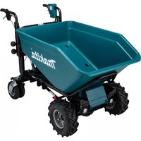
| Product Type | Electric Wheelbarrow |
| Brand | Makita |
| Model | DCU604 |
| Dimensions (L x W x H) with bucket | 1480 mm x 730 mm x 820 - 1030 mm |
| Net weight (with bucket) | 122 - 124 kg |
| Power supply | 36 V DC, Li-ion battery |
| Compatible batteries | BL1815N, BL1820B, BL1830B, BL1840B, BL1850B, BL1860B |
| Compatible chargers | DC18RC, DC18RD, DC18RE, DC18SD, DC18SE, DC18SF, DC18SH, DC18WC |
| Travel speeds | Forward: 5.0 / 3.5 / 1.5 km/h Reverse: 1.0 km/h |
| Maximum load capacity (flat ground) | 300 kg |
| Load capacity on slope (3° - 12°) | 180 kg |
| Maximum flat bucket capacity | 250 liters |
| Grade ability | 12° |
| Minimum turning radius | 1150 mm |
| Brake | Hand brake and support brake |
| Tire pressure | Front: 280 kPa (40 PSI) Rear: 525 kPa (75 PSI) |
| Protection degree | IPX4 |
| Sound level (pressure) | 70 dB(A) or less |
| Vibration (no-load operation) | 2.5 m/s² or less |
| Main functions | Forward/reverse, 3 speeds, LED lighting, audible signal, tipping discharge, rear wheel lock, handle height adjustment |
| Maintenance | Water cleaning, bolt inspection, tire inflation |
| Safety | Parking brake, battery protection system, safety key, automatic stop |
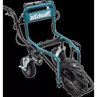
| Optional accessories | Cart, bucket, flat bucket, discharge unit, spare tires |
Frequently Asked Questions - DCU604 MAKITA
User questions about DCU604 MAKITA
0 question about this device. Answer the ones you know or ask your own.
Ask a new question about this device
Download the instructions for your Electric wheelbarrow in PDF format for free! Find your manual DCU604 - MAKITA and take your electronic device back in hand. On this page are published all the documents necessary for the use of your device. DCU604 by MAKITA.
USER MANUAL DCU604 MAKITA
| EN | Battery Powered Wheelbarrow | INSTRUCTION MANUAL 17 |
| FR | Brouette À Batterie MANUEL D’INSTRUCTIONS 32 | |
| DE | Akku-Schubkarre BETRIEBSANLEITUNG 49 | |
| IT | Carriola elettrica a batteria ISTRUZIONI PER L’USO 66 | |
| NL | Accuaangedreven kruiwagen GEBRUIKSAANWIJZING 83 | |
| ES | Carretilla Propulsada a Batería | MANUAL DE INSTRUCCIONES 99 |
| PT | Carrinho de Mão a Bateria MANUAL DE INSTRUÇÕES 116 | |
| DA | Batteridrevet trillebør BRUGSANVISNING 132 | |
| EL | Καρότσι με μπαταρία ΕΓΧΕΙΡΙΔΙΟ ΟΔΗΓΙΩΝ | 147 |
| TR | Akülü El Arabası | KULLANMA KILAVUZU 164 |
DCU603 DCU604 DCU605

natural_image
Line drawings of three different types of manual push-wet tractors with wheels and wheels (no text or symbols)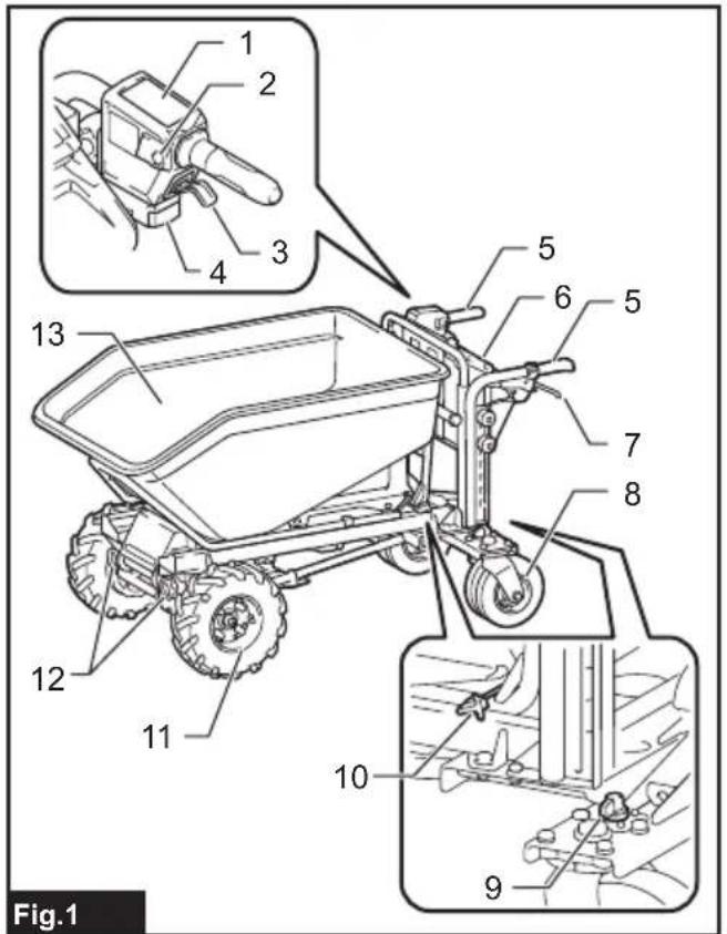
natural_image
Technical line drawings of two toy vehicle components: a wheeled cart and a multi-wheeled chassis (no text or symbols)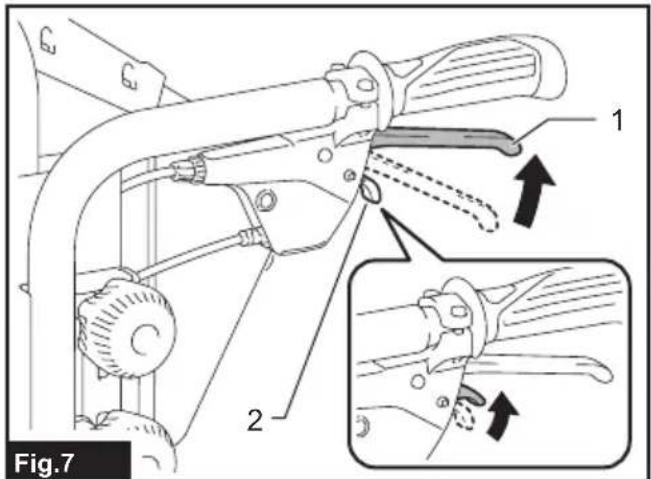


natural_image
Illustration of two workers pushing a cart with a guide, showing mechanical components and a downward arrow indicating motion (no text or symbols)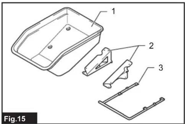

natural_image
Line drawing of a vehicle chassis with four compartments and support frames (no text or symbols)
natural_image
Technical line drawing of two plastic crates with labeled parts (1 and 2), no text or symbols present.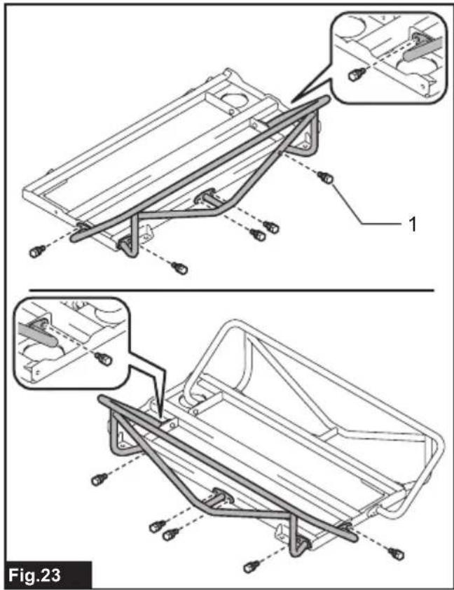
natural_image
Illustration showing two workers pushing a cart before and after a pull-up, with no text or symbols present.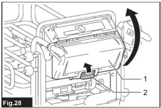
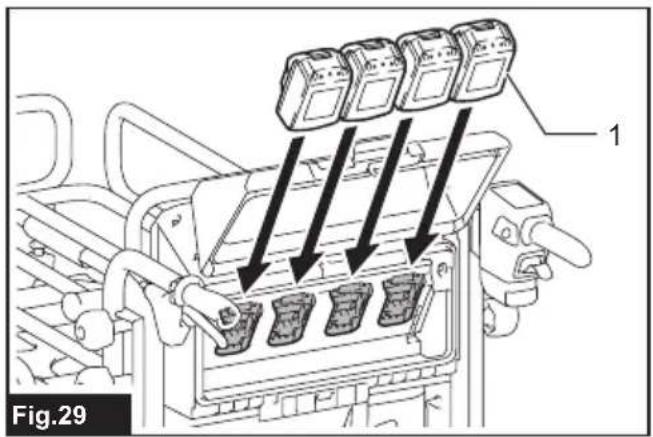
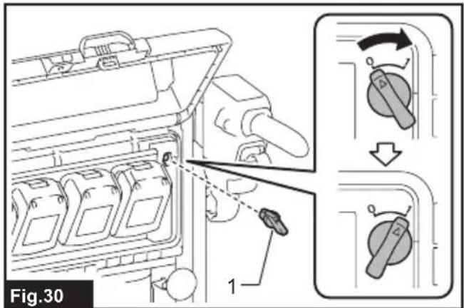
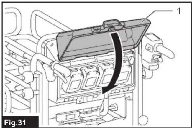
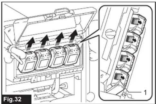
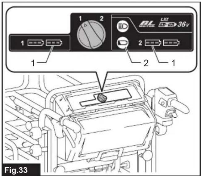
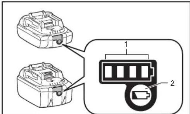
Fig.34
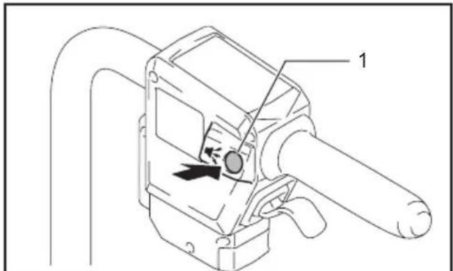
Fig.38
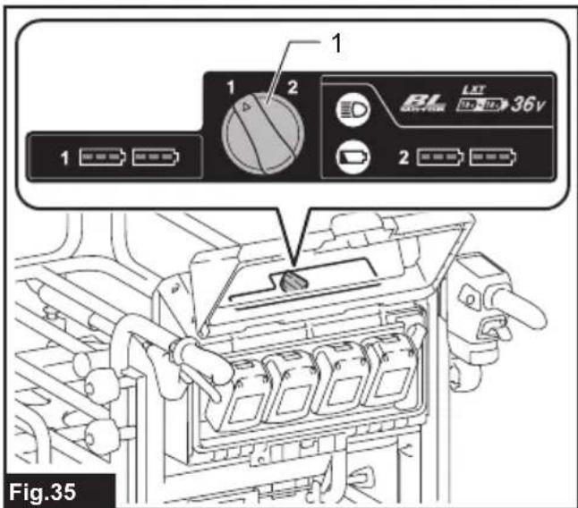
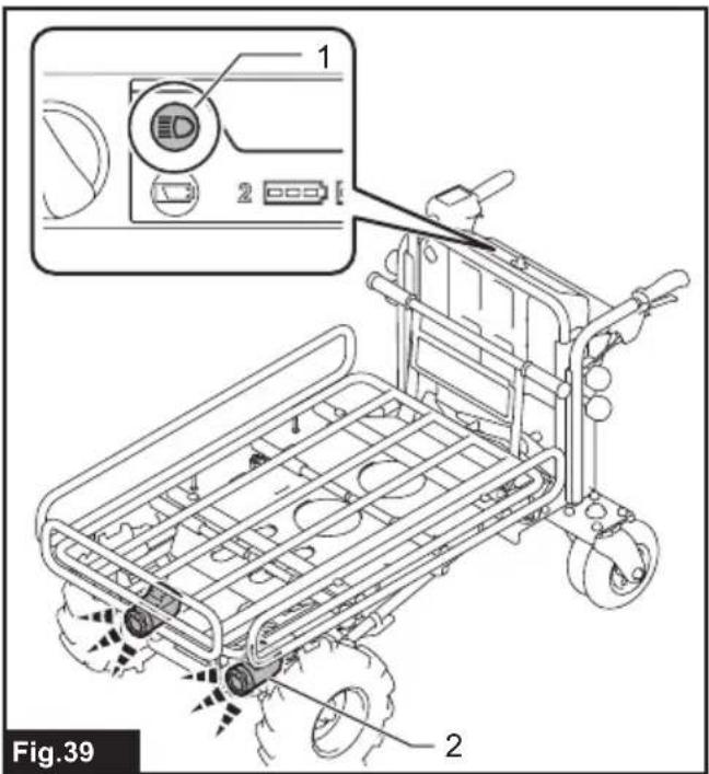
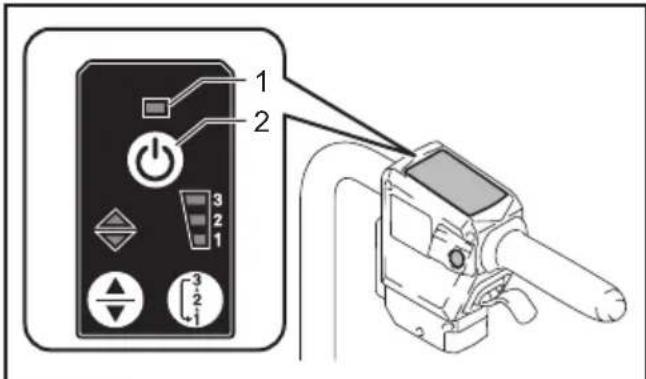
Fig.36
natural_image
Technical line drawing of a mechanical assembly with no visible text or symbols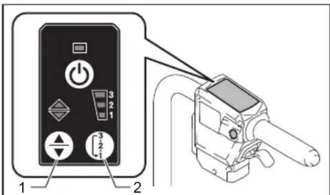
Fig.37

natural_image
Technical line drawing of a mechanical assembly with no visible text or symbols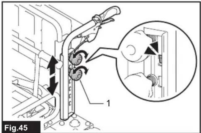
natural_image
Technical line drawing of a mechanical assembly with labeled component '1' (no text or symbols beyond label)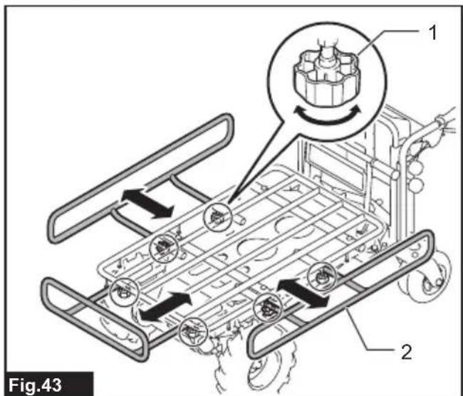
natural_image
Technical diagram showing two installation methods with a no-smoking symbol above (no text or labels present)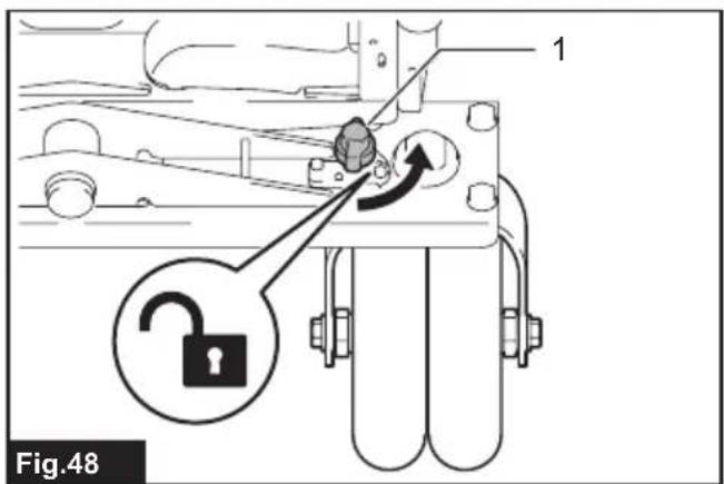
natural_image
Four-panel technical diagram showing mechanical assembly or valve configurations, with arrows indicating direction of movement (no text or symbols present)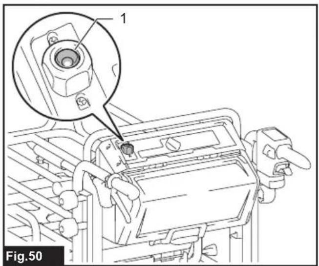
natural_image
Technical line drawing of a mechanical tool with labeled component '1' (no text or symbols beyond label)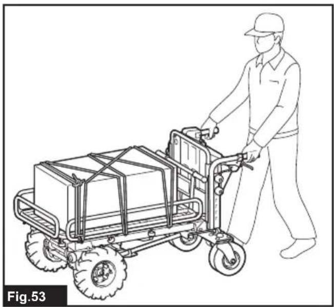
natural_image
Line drawing of a worker pushing a cart loaded with boxes (no text or symbols)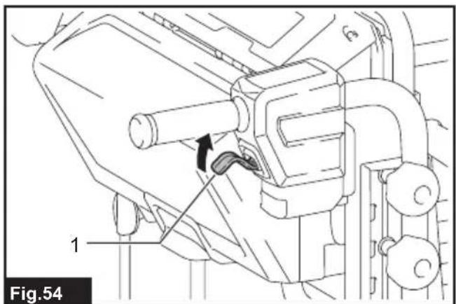
natural_image
Technical line drawing of a mechanical assembly with labeled component 1 (no text or symbols beyond label)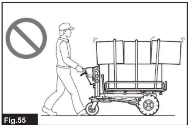
natural_image
Illustration of a worker pushing a cart with a no-smoking symbol (no text or labels)
natural_image
Illustration of a worker pushing a pallet cart with a no-smoking symbol (no text or labels)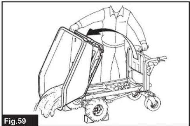
natural_image
Line drawing of a person pushing a cart with wheels, labeled Fig.59 (no text or symbols on the diagram itself)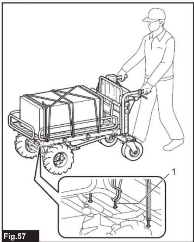
natural_image
Line drawing of a worker pushing a wheeled cart with a component, showing mechanical assembly details (no text or symbols)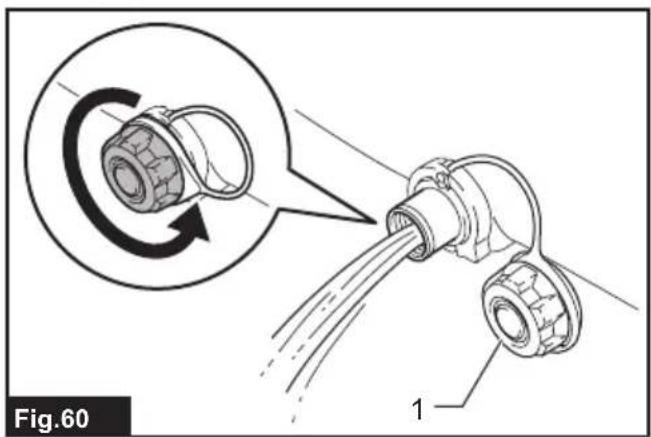
natural_image
Technical line drawing of a wheeled cart with a magnified inset showing a hand holding a tool, labeled Fig.58 (no text or symbols on the diagram itself)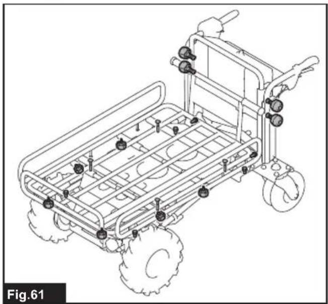
natural_image
Line drawing of a wheeled toy car with wheels and mounting feet (no text or symbols)
natural_image
Technical line drawing of a wheeled vehicle chassis with labeled components (no text or symbols beyond labels)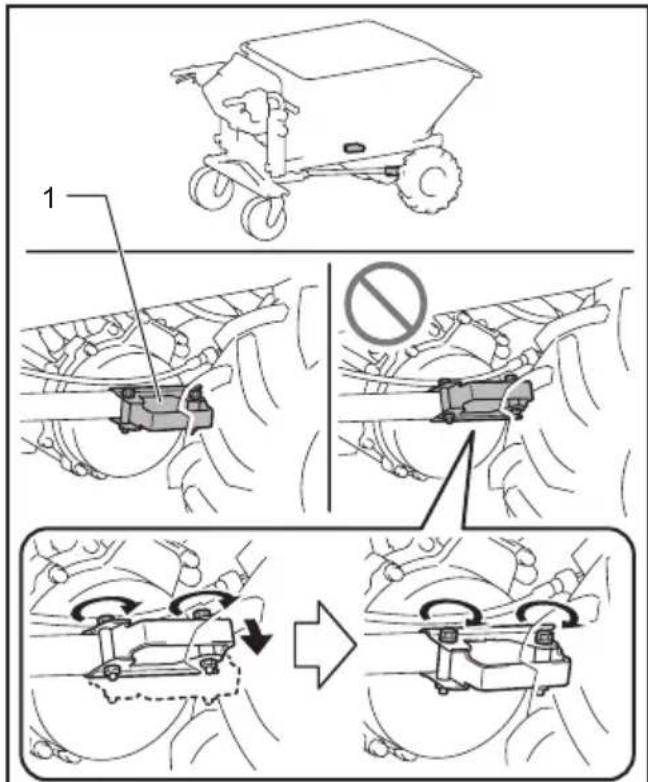
Fig.63
natural_image
Technical line drawing of a vehicle's lower body and suspension system, showing gear and brake components (no text or symbols)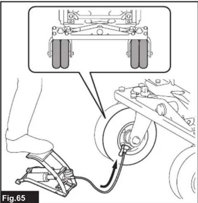
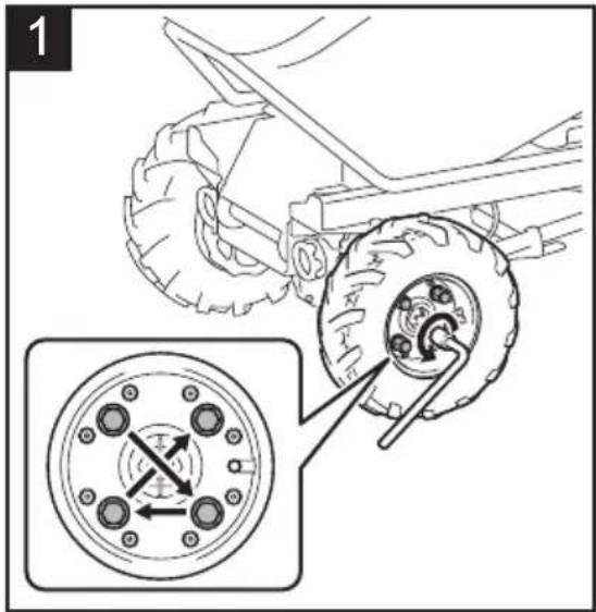
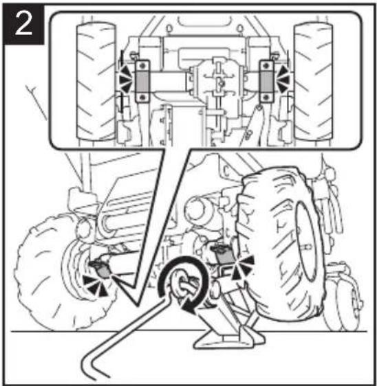
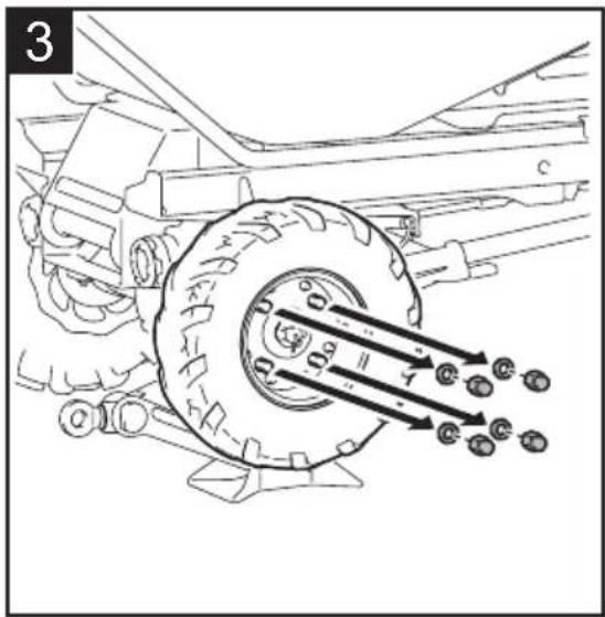
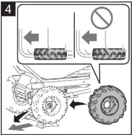
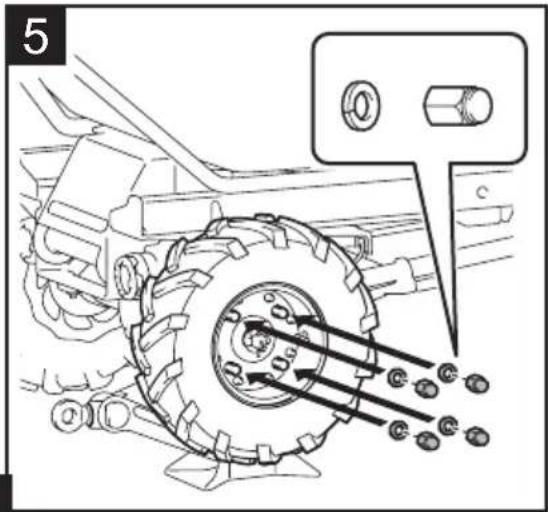
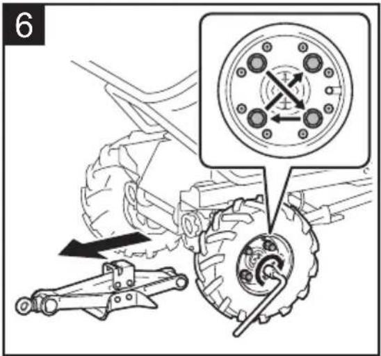
Fig.66

natural_image
Technical line drawing of a vehicle chassis with wheels and a mechanical clamp (no text or symbols)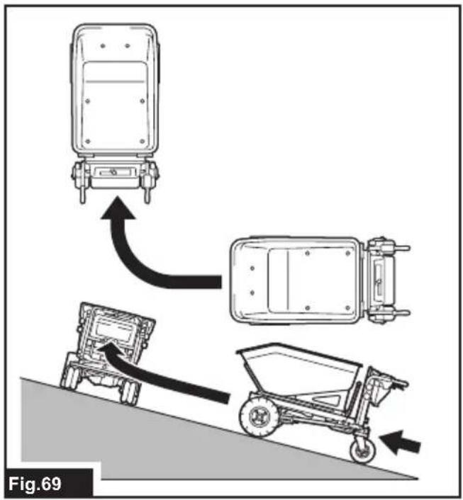
SPECIFICATIONS
| Model: DCU603 DCU604 DCU605 | ||||
| Dimensions(L x W x H) | When bucket is installed 1,480 mm | mm x 730 mm x 820 - 1,030 mm | ||
| When carrier is installed 1,450 - 1,600 mm x 730 - 1,080 mm x 820 - 1,030 mm | ||||
| When flat bucket is installed 1,440 mm x 730 mm x 820 - 1,030 mm | ||||
| Traveling speed Forward 5.0 / 3.5 / 1.5 km/h | ||||
| Maximum load capacity On flat ground 300 kg | ||||
| On slope (3° - 12°) 180 kg | ||||
| Maximum capacity of flat bucket 250 liter | ||||
| Maximum climbing capacity 12° | ||||
| Minimum turning radius * 1,150 mm | ||||
| Brake | Hand brake and support brake | |||
| Tire | Front wheel | Pneumatic tire | ||
| Rear wheel | Pneumatic tire | |||
| Rated voltage | D.C. 36 V | |||
| Net weight When bucket is installed | 122 - 124 kg | |||
| When carrier is installed | 119 - 120 kg | |||
| When flat bucket is installed | 104 - 106 kg | |||
| Protection degree | IPX4 | |||
*: Outer diameter when turning with front wheel as axis.
• Due to our continuing program of research and development, the specifications herein are subject to change without notice.
• Specifications may differ from country to country.
- The weight may differ depending on the attachment(s), including the battery cartridge. The lightest and heaviest combinations, according to EPTA-Procedure 01/2014, are shown in the table.
Applicable battery cartridge and charger
| Battery cartridge | BL1815N / BL1820B / BL1830B / BL1840B / BL1850B / BL1860B |
| Charger | DC18RC / DC18RD / DC18RE / DC18SD / DC18SE / DC18SF / DC18SH / DC18WC |
- Some of the battery cartridges and chargers listed above may not be available depending on your region of residence.

WARNING: Only use the battery cartridges and chargers listed above. Use of any other battery cartridges I chargers may cause injury and/or fire.

WARNING: Never use Portable Power Pack PDC1200 or PDC01 with this product. Using them together, cause personal injury or malfunction.
Symbols
The followings show the symbols which may be used for the equipment. Be sure that you understand their meaning before use.

Read instruction manual.

Do not change direction on slopes.

This machine cannot be used on public roads.
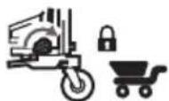
Before loading or unloading objects, lock the brake and dump unit.

Do not load or unload objects on slopes.

Do not use the machine for transporting people.

Do not dump objects on slopes. Lock the dump unit after dumping.

Load objects on the bucket or carrier evenly. Do not load objects unevenly or only on front side.

Pinch and crush hazard. Keep hands clear during operation. Do not put your hands or part of your body into the moving parts.

Maximum load capacity: 300 kg on flat ground and 180 kg on slopes (up to 12°).

Do not directly look into lamps.

Do not wash the machine with high pressure washer.

Keep bystanders away from the machine during operation.

Do not operate the machine around uneven surfaces.

Do not operate the machine when the bucket or carrier is not returned completely.

Remove ropes before dumping objects.

Always wear non-slip and protective footwear.
Lock the brake before pulling out the neutral change lever.
Lock the brake before returning the neutral change lever.
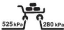
Air pressure: front tire 280 kPa and rear tire 525 kPa.

Make sure that the lock lever is locked.
Turn the lock lever toward the front of machine to unlock the dump unit.
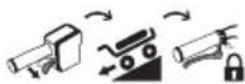
When a beep sound is emitted, lock the brake lever.
When you release the switch trigger, lock the brake lever.

Ni-MH Li-ion

Guaranteed sound power level according to EU Outdoor Noise Directive.

Sound power level according to Australia NSW Noise Control Regulation.
Intended use
The machine is intended for loading and carrying objects with battery powered assistance.
Noise
The typical A-weighted noise level determined according to EN62841-1 and EN12053 as applicable: Sound pressure level ( L_pA ): 70 dB(A) or less Uncertainty (K): 4 dB (A)
The noise level under working may exceed 80 dB (A).
NOTE: The declared noise emission value(s) has been measured in accordance with a standard test method and may be used for comparing one tool with another.
NOTE: The declared noise emission value(s) may also be used in a preliminary assessment of exposure.

WARNING: Wear ear protection.
⚠ WARNING: The noise emission during actual use of the power tool can differ from the declared value(s) depending on the ways in which the tool is used especially what kind of workpiece is processed.
⚠ WARNING: Be sure to identify safety measures to protect the operator that are based on an estimation of exposure in the actual conditions of use (taking account of all parts of the operating cycle such as the times when the tool is switched off and when it is running idle in addition to the trigger time).
Vibration
The vibration total value (tri-axial vector sum) determined according to EN62841-1:
Work mode: operation without load
Vibration emission (ah): 2.5 m/s ^2 or less
Uncertainty (K) : 1.5 m/s²
NOTE: The declared vibration total value(s) has been measured in accordance with a standard test method and may be used for comparing one tool with another.
NOTE: The declared vibration total value(s) may also be used in a preliminary assessment of exposure.

WARNING: The vibration emission during actual use of the power tool can differ from the declared value(s) depending on the ways in which the tool is used especially what kind of workpiece processed.
⚠ WARNING: Be sure to identify safety measures to protect the operator that are based on an estimation of exposure in the actual conditions of use (taking account of all parts of the operating cycle such as the times when the tool is switched off and when it is running idle in addition to the trigger time).
Declarations of Conformity
For European countries only
The Declarations of conformity are included in Annex A to this instruction manual.
SAFETY WARNINGS
General power tool safety warnings
WARNING: Read all safety warnings, instructions, illustrations and specifications provided with this power tool. Failure to follow all instructions listed below may result in electric shock, fire and/or serious injury.
Save all warnings and instructions for future reference.
The term "power tool" in the warnings refers to your mains-operated (corded) power tool or battery-operated (cordless) power tool.
Battery powered wheelbarrow safety warnings
-
While operating the machine, always wear non-slip and protective footwear. Non-skid, closed-toed safety boots and shoes will reduce the risk of injury.
-
Inspect pathway before hauling objects/materials. Familiarizing yourself with the pathway and ensuring it is wide enough to safely navigate the machine under load will help reduce losing control of the machine.
-
Use extreme caution on slippery, loose and unstable terrain. Wet and slippery surfaces, such as wet grassy areas, snow or ice, and loose and unstable terrain, such as sand or gravel surfaces, may cause the machine to lose traction and may adversely affect steering, braking and stability.
-
Do not operate the machine on excessively steep slopes. This reduces the risk of loss of control, slipping and falling which may result in personal injury. Slopes greater than the maximum recommended grade and side grades may increase the risk of instability and may adversely affect the ability to stop safely.
-
When working on slopes, always be sure of your footing, always work across the face of slopes, never up or down, and exercise extreme caution when changing direction. This reduces the risk of loss of control, slipping and falling which may result in personal injury.
-
Whenever possible, use level areas for stopping, loading and unloading and never leave machine unattended on a slope. The machine is more unstable when resting on a slope than when resting on a level surface.
-
When leaving the machine unattended, set parking brake once the machine is located in a safe stopping area. The parking brake prevents unwanted movement of the front wheel and can improve stability.
-
Ensure that ramps are clean, strong and secure. In order to reduce the risk of injury, all ramps must be clear of loose debris and strong enough to withstand the weight of anticipated loads that will be moved over them. They must have adequate blocking underneath and to both sides to eliminate deflections and side-to-side movement under load. All ramps must be wide enough to have sure footing while hauling loads across them.
- Ensure all locking screws are tightly secure before using. Locking screws on the rear wheels and open-type carrier front and side walls must be secure to prevent unwanted movement of these adjustable parts of the machine.
- Never operate the machine in an overloaded condition. Make sure the machine has the proper capacity rating for the objects or materials that have to be hauled. Excessive loads will make the machine more difficult to maneuver and stop, will increase stopping time and distance, and will increase the risk of instability.
- Never operate your machine in an over stacked condition. Stacking material above the tray rim or over the sides of the tray can cause the machine to be uncontrollably out of balance and control.
- Use containers and tie-downs to secure loads. Loose and/or insecure loads are more likely to shift which can result in loss of stability and control.
- Always maintain a firm grip on handles. Loss of control can increase the risk of personal injury.
- Remove safety key when not in use. The safety key prevents unwanted, powered use of the machine, such as by children or other untrained or unauthorized persons. Without the key, electric power cannot be turned "on".
- This machine cannot be used on public roads. Use of the wheelbarrow on a public road is unlawful and could result in local jurisdiction penalties in addition it could result in personal injury.
- Use a sturdy plate with anti-slip and detachment prevention function when loading and/or unloading this machine for transportation, or moving this machine between different levels. Make sure the plate inclination does not exceed 12^ , and operate the machine slowly and carefully. Unstable and quick operation may result in overturn and/or falling.
- Do not disassemble, repair, or modify this machine.
Preparation
-
Before operating the machine, make sure that there are no people around the machine.
-
Before operating the machine, perform the inspections referring to the section for maintenance.
Operation
- When operating the machine, stand behind the machine and hold the handles with both hands firmly.
- Do not operate the machine while riding on the machine.
-
Do not allow others to ride on the machine.
-
When operating the machine in reverse and walking backward, watch behind you and watch your step, and be careful not to slip or trip.
- Do not use the machine when visibility is poor because there is a risk of striking obstacles.
- When operating the machine on rough ground or going over the level difference of the road, decrease speed and exercise caution.
- When using the machine, avoid soft ground to prevent overturn due to the shoulder of the road collapsing.
- Do not operate the machine on upward slopes greater than 12^ .
- If you find an abnormality, stop the machine on flat ground. Before inspecting the machine, lock the brake lever, and then turn the power off.
- Before operating the machine, make sure that the handle of the dump unit is fully pulled down and completely locked. If the lock is incomplete, there is a risk of accident or injury as the carrier or bucket may be tilted and the objects fall when going downhill.
- When operating the machine near walls, be careful not to get your hands caught between the handle and the wall.
- Do not use the machine in bad weather conditions, especially when there is a risk of lightning. This decreases the risk of being struck by lightning.
- Do not touch the metal parts during use or after use as they may get hot enough to cause burns due to sunlight.
- Be careful not to entangle the cords with the load or obstacles.
- When crossing a wooden bridge, etc., make sure that the sum of the weight of product, load capacity, and operator's weight does not exceed the weight limit of the bridge, and cross the bridge carefully at a constant speed.
- Wear the gloves when operating the machine in low temperature environments. Touching the metal parts with bare hands may cause your hands to stick.
- If there are people or obstacles in the direction of travel, avoid them in advance.
- Do not scoop objects directly with the carrier or bucket. Doing so may damage the machine and cause an accident.
- When you use the machine on muddy ground, wet slope, or slippery place, pay attention to your footing.
- Do not submerge the machine into a puddle.
Operation on slopes
- Do not cross on slopes.
- Stop before the downhill, and be sure to decrease speed and exercise caution.
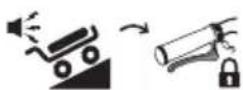
- If the speed is too fast when traveling downhill, the beep sound is emitted. In this case, slow down using the brake.
-
Exercise caution when starting or stopping the machine on slopes.
-
As the loads become less stable on slopes, firmly secure the loads with ropes.
- As the machine becomes unstable depending on the condition of the road, keep the load to a minimum.
- As the view is obscured on slopes, keep the height of the load to a minimum.
- Never stop the machine on slopes. Stop the machine on flat ground, and lock the brake lever, and then turn the power off.
- Do not change the direction or speed mode on steep slopes.
- Do not release the switch trigger on upward slopes. The machine may go in reverse and cause an accident.
- Make sure that the remaining battery capacity is enough before operating on slopes. If the remaining battery capacity is not enough, charge the battery or replace it with a charged one.
- When starting the machine on slopes, do not place your foot behind the rear wheel since the machine moves back a few centimeters.
Loading objects
- Do not overload objects. When loading objects, be sure to follow the instructions and load limits in the manual.
- Since the larger the load, the more difficult it is to operate the machine, keep the load within the range that does not affect the operation.
- Firmly secure the objects with ropes.
- Load the objects within the carrier, bucket, or flat bucket. If the objects protrude from the carrier, bucket, or flat bucket, there is a risk of accidents due to the objects falling or contact obstacles such as walls.
- Be sure that loaded objects are below eye level. If the load is too high, it is dangerous because the view is obscured. Also, there is a risk of overturning and injury because the load is likely to be unbalanced.
- Load the objects on the carrier, bucket, or flat bucket evenly. If the objects are loaded unevenly, there is a risk of overturning and injury because the load is likely to be unbalanced.
- Before loading the objects or operating the machine, make sure that the handle of the dump unit is fully pulled down and completely locked.
- Be sure to load heavy objects first to keep balance.
- Do not extend the front and side rails on steep slopes. Extend the side rails when lightweight objects are loaded.
- When extending the front and side rails, do not extend them over the extension limit. Be sure to extend the side rails so that the right and left sides are the same length, and load objects evenly.
- Load and unload objects on flat ground. Never load or unload objects on slope.
-
When lifting and tilting the carrier or bucket, hold the handles and frame firmly, and work in a stable posture.
-
When loading liquids, be careful not to spill them. Spilling them may cause slipping and cause an injury.
Transportation of machine
- Use the ladder rails that are at least 4 times as long as the height of the truck bed, with fixtures suitable for the bed, with a non-slip surface and sufficient width, and capable of withstanding the weight of the machine and operator. Read the instruction manual of the ladder rails carefully before use.
- Before loading the machine, unload all objects from the machine and remove mud and other debris from the tires. Install the ladder rails on a flat and stable surface.
-
Before loading or unloading the machine, make sure that there are no people around the machine and the ladder rails. Load or unload the machine at low speed, taking care to prevent the machine from falling off the ladder rails, and not to hit your head on the ceiling of the truck. Use extreme caution when loading or unloading the machine backward.
-
When transporting the machine, lock the brake lever, turn the power off, remove the batteries and lock key, and fix the machine securely.
Maintenance and storage
- Before storage or attempting to perform inspections or maintenance, always be sure to stop the machine on flat ground and lock the brake lever, and turn off the machine, and remove the lock key and battery cartridges.
- Do not leave the machine unattended outdoors in the rain.
- When storing the machine, avoid direct sunlight and rain, and store it in a place where it does not get hot or humid.
Battery tool use and care
- Recharge only with the charger specified by the manufacturer. A charger that is suitable for one type of battery pack may create a risk of fire when used with another battery pack.
- Use power tools only with specifically designated battery packs. Use of any other battery packs may create a risk of injury and fire.
- When battery pack is not in use, keep it away from other metal objects, like paper clips, coins, keys, nails, screws or other small metal objects, that can make a connection from one terminal to another. Shorting the battery terminals together may cause burns or a fire.
- Under abusive conditions, liquid may be ejected from the battery; avoid contact. If contact accidentally occurs, flush with water. If liquid contacts eyes, additionally seek medical help. Liquid ejected from the battery may cause irritation or burns.
- Do not use a battery pack or tool that is damaged or modified. Damaged or modified batteries may exhibit unpredictable behaviour resulting in fire, explosion or risk of injury.
-
Do not expose a battery pack or tool to fire or excessive temperature. Exposure to fire or temperature above 130 °C may cause explosion.
-
Follow all charging instructions and do not charge the battery pack or tool outside the temperature range specified in the instructions. Charging improperly or at temperatures outside the specified range may damage the battery and increase the risk of fire.
Electrical and battery safety
- Do not dispose of the battery(ies) in a fire. The cell may explode. Check with local codes for possible special disposal instructions.
- Do not open or mutilate the battery(ies). Released electrolyte is corrosive and may cause damage to the eyes or skin. It may be toxic if swallowed.
- Do not charge battery in rain, or in wet locations.
- Do not charge the battery outdoors.
- Do not handle charger, including charger plug, and charger terminals with wet hands.
- Do not replace the battery in the rain.
- Do not wet the terminal of battery with liquid such as water, or submerge the battery. Do not leave the battery in the rain, nor charge, use, or store the battery in a damp or wet place. If the terminal gets wet or liquid enters inside of battery, the battery may be short circuited and there is a risk of overheat, fire, or explosion.
- After removing the battery from the machine or charger, be sure to attach the battery cover to the battery and store it in a dry place.
- Do not replace the battery with wet hands.
- Avoid dangerous environment. Don't use the machine in dump or wet locations or expose it to rain. Water entering the machine will increase the risk of electric shock.
- If the battery cartridge gets wet, drain the water inside and then wipe it with a dry cloth. Dry the battery cartridge completely in a dry place before use.
SAVE THESE INSTRUCTIONS.
⚠ WARNING: DO NOT let comfort or familiarity with product (gained from repeated use) replace strict adherence to safety rules for the subject product. MISUSE or failure to follow the safety rules stated in this instruction manual may cause serious personal injury.
Important safety instructions for battery cartridge
- Before using battery cartridge, read all instructions and cautionary markings on (1) battery charger, (2) battery, and (3) product using battery.
- Do not disassemble or tamper with the battery cartridge. It may result in a fire, excessive heat, or explosion.
-
If operating time has become excessively shorter, stop operating immediately. It may result in a risk of overheating, possible burns and even an explosion.
-
If electrolyte gets into your eyes, rinse them out with clear water and seek medical attention right away. It may result in loss of your eyesight.
- Do not short the battery cartridge:
(1) Do not touch the terminals with any conductive material.
(2) Avoid storing battery cartridge in a container with other metal objects such as nails, coins, etc.
(3) Do not expose battery cartridge to water or rain.
A battery short can cause a large current flow, overheating, possible burns and even a breakdown.
- Do not store and use the tool and battery cartridge in locations where the temperature may reach or exceed 50 °C (122 °F).
- Do not incinerate the battery cartridge even if it is severely damaged or is completely worn out. The battery cartridge can explode in a fire.
- Do not nail, cut, crush, throw, drop the battery cartridge, or hit against a hard object to the battery cartridge. Such conduct may result in a fire, excessive heat, or explosion.
- Do not use a damaged battery.
- The contained lithium-ion batteries are subject to the Dangerous Goods Legislation requirements. For commercial transports e.g. by third parties, forwarding agents, special requirement on packaging and labeling must be observed. For preparation of the item being shipped, consulting an expert for hazardous material is required. Please also observe possibly more detailed national regulations. Tape or mask off open contacts and pack up the battery in such a manner that it cannot move around in the packaging.
- When disposing the battery cartridge, remove it from the tool and dispose of it in a safe place. Follow your local regulations relating to disposal of battery.
- Use the batteries only with the products specified by Makita. Installing the batteries to non-compliant products may result in a fire, excessive heat, explosion, or leak of electrolyte.
- If the tool is not used for a long period of time, the battery must be removed from the tool.
- During and after use, the battery cartridge may take on heat which can cause burns or low temperature burns. Pay attention to the handling of hot battery cartridges.
- Do not touch the terminal of the tool immediately after use as it may get hot enough to cause burns.
-
Do not allow chips, dust, or soil stuck into the terminals, holes, and grooves of the battery cartridge. It may cause heating, catching fire, burst and malfunction of the tool or battery cartridge, resulting in burns or personal injury.
-
Unless the tool supports the use near high-voltage electrical power lines, do not use the battery cartridge near high-voltage electrical power lines. It may result in a malfunction or breakdown of the tool or battery cartridge.
- Keep the battery away from children.
SAVE THESE INSTRUCTIONS.
⚠️CAUTION: Only use genuine Makita batteries.
Use of non-genuine Makita batteries, or batteries that have been altered, may result in the battery bursting causing fires, personal injury and damage. It will also void the Makita warranty for the Makita tool and charger.
Tips for maintaining maximum battery life
- Charge the battery cartridge before completely discharged. Always stop tool operation and charge the battery cartridge when you notice less tool power.
- Never recharge a fully charged battery cartridge. Overcharging shortens the battery service life.
- Charge the battery cartridge with room temperature at 10 °C - 40 °C ( 50 °F - 104 °F ). Let a hot battery cartridge cool down before charging it.
- When not using the battery cartridge, remove it from the tool or the charger.
- Charge the battery cartridge if you do not use it for a long period (more than six months).
PARTS DESCRIPTION
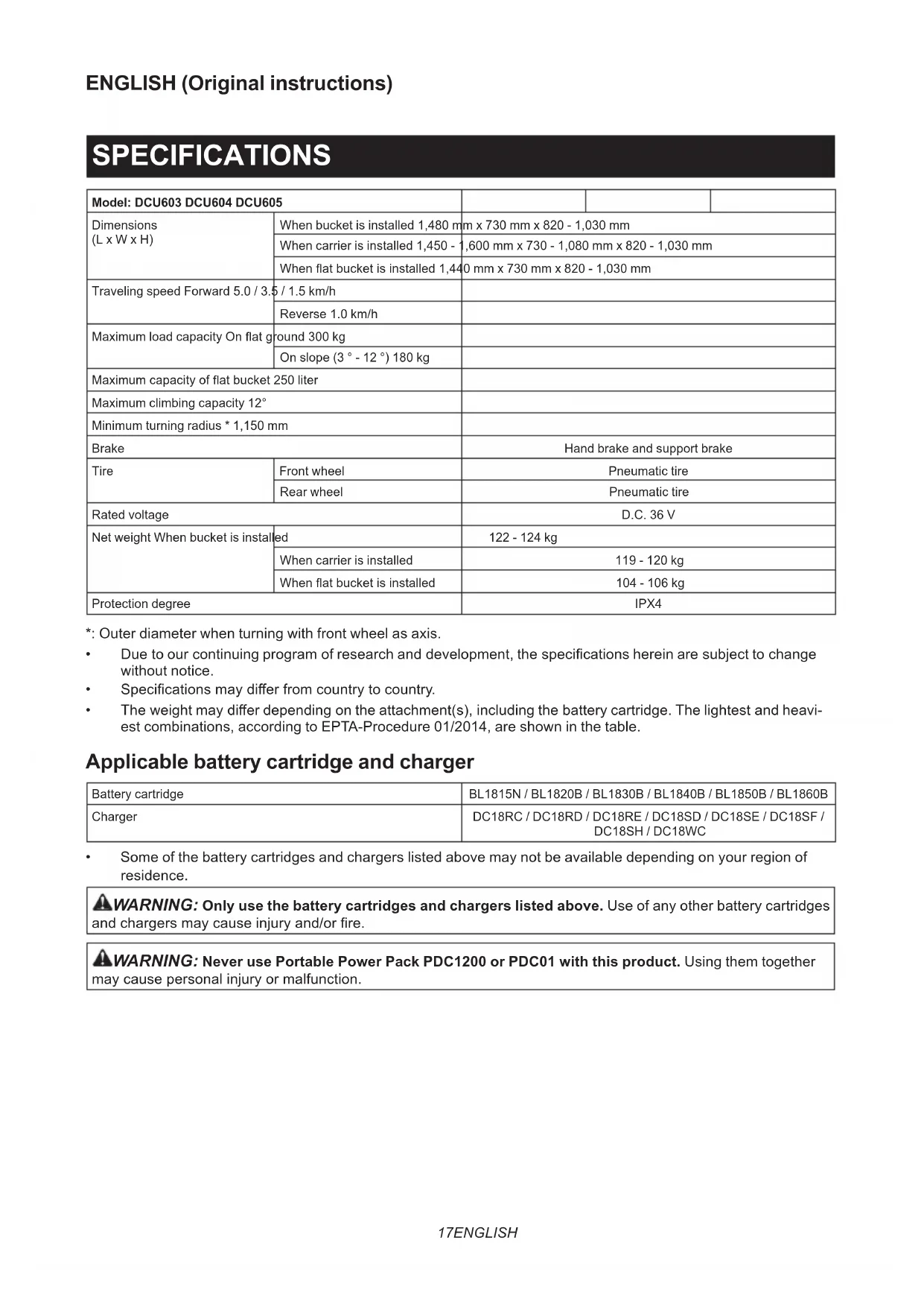
DCU603
▶ Fig.1
| 1 Control panel 2 Beep button | ||
| 3 Switch trigger 4 Rear lamp | ||
| 5 Handle 6 Battery box | ||
| 7 Brake lever 8 Rear wheel | ||
| 9 Rear wheel lock 10 Lock lever | ||
| 11 Front wheel 12 Front lamp | ||
| 13 Bucket -- |
DCU604
▶ Fig.2
| 1 Control panel 2 Beep button | ||
| 3 Switch trigger 4 Rear lamp | ||
| 5 Handle 6 Battery box | ||
| 7 Brake lever 8 Rear wheel | ||
| 9 Rear wheel lock 10 Lock lever | ||
| 11 Front wheel 12 Front lamp | ||
| 13 Carrier - - |
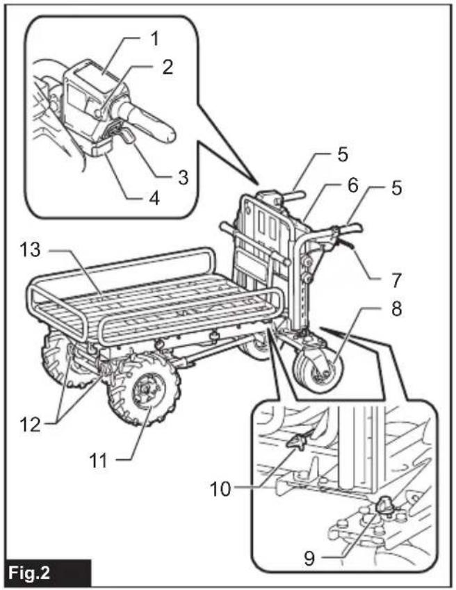
DCU605
▶ Fig.3
| 1 Control panel 2 Beep button | ||
| 3 Switch trigger 4 Rear lamp | ||
| 5 Rear wheel lock | 6 Handle | |
| 7 Battery box 8 Brake lever | ||
| 9 Rear wheel 10 Front wheel | ||
| 11 Front lamp 12 Cap | ||
| 13 Flat bucket | -- | |
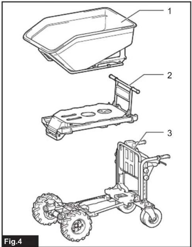
CONFIGURATION OF MACHINE
When the bucket is installed
▶ Fig.4
| 1 Bucket | 2 Dump unit |
| 3 Base unit | -- |
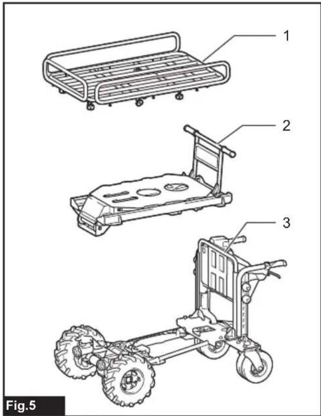
When the carrier is installed
▶ Fig.5
| 1 Carrier | 2 Dump unit |
| 3 Base unit | -- |
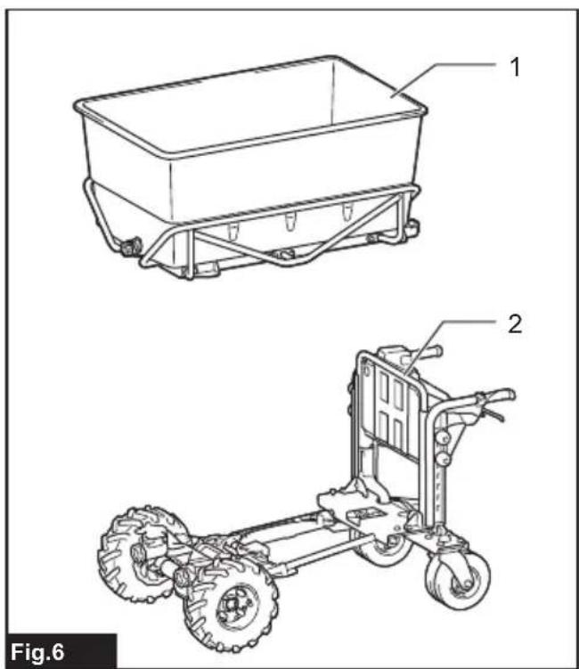
When the flat bucket is installed
▶ Fig.6
| 1 Flat bucket | 2 Base unit |
ASSEMBLY
CAUTION: Always be sure that the machine is switched off and the battery cartridges are removed before carrying out any work on the machine.
Before installing or removing the carrier, bucket, flat bucket, or dump unit, be sure to lock the brake lever. To lock the brake lever, pull and hold the brake lever, then pull the lock lever, and then release the brake lever while pulling the lock lever.
▶ Fig.7: 1. Brake lever 2. Lock lever
Installing or removing the dump unit
Optional accessory
Installing the dump unit
- Take out the dump unit and the handle from the box.
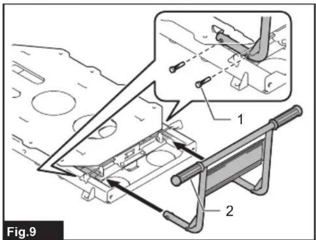
▶ Fig.8: 1. Dump unit 2. Handle - Insert the pipes of the handle into the dump unit as shown in the figure, and then tighten 4 bolts securely.
▶ Fig.9: 1. Bolt 2. Handle
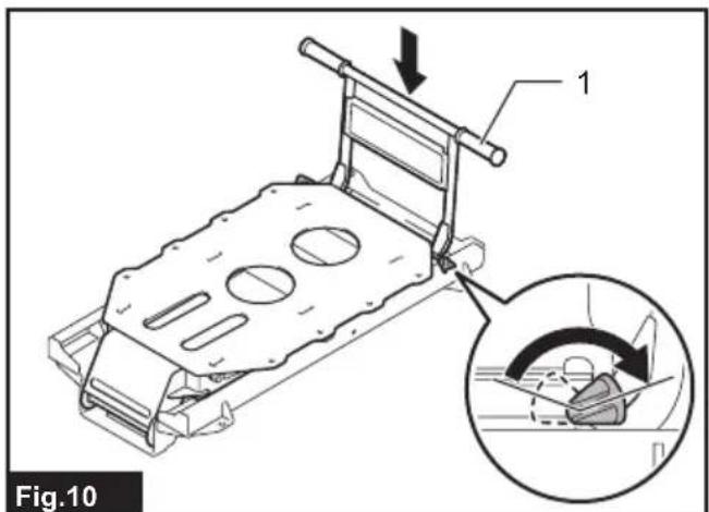
NOTE: When tightening the bolts, lift the handle slightly. - Make sure that the dump unit is locked by pulling down the handle.
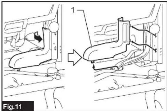
▶ Fig.10: 1. Handle - Remove the cord cover located in the lower right corner on the rear of the machine.
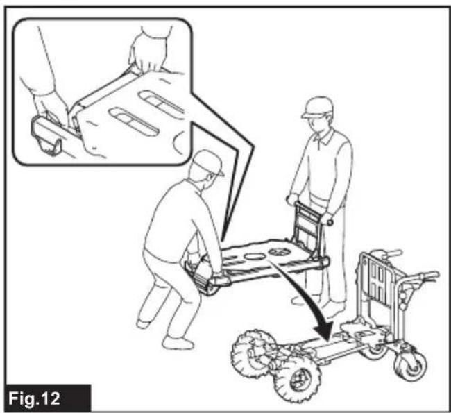
▶ Fig.11: 1. Cord cover - Place the dump unit on the base unit by holding the dump unit with two people as shown in the figure.
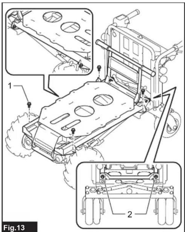
▶ Fig.12 - Temporarily tighten 2 bolts at the rear of the machine. Tighten the rest of 4 bolts securely, and then tighten 2 bolts at the rear of the machine securely.
▶ Fig.13: 1. Bolt (front) 2. Bolt (rear) - Attach the cord cover.
▶ Fig.14: 1. Cord cover
Removing the dump unit
To remove the dump unit, perform the installation procedure in reverse.
Installing or removing the bucket
Optional accessory
Installing the bucket
- Take out the bucket, stays, and front pipe from the box.
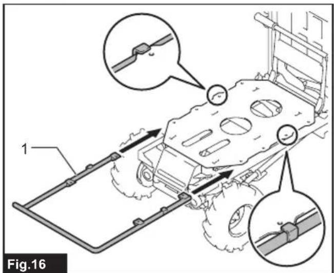
▶ Fig.15: 1. Bucket 2. Stay 3. Front pipe - Insert the front pipe between the upper frame and lower frame of the dump unit.
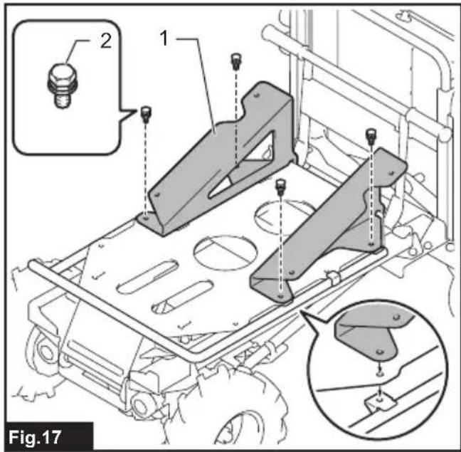
▶ Fig.16: 1. Front pipe - Place the stay on the dump unit, and then temporarily tighten the bolts with the front pipe together. Install the other stay to the dump unit in the same way.
▶ Fig.17: 1. Stay 2. Bolt - Place the bucket on the front pipe and left and right stays.
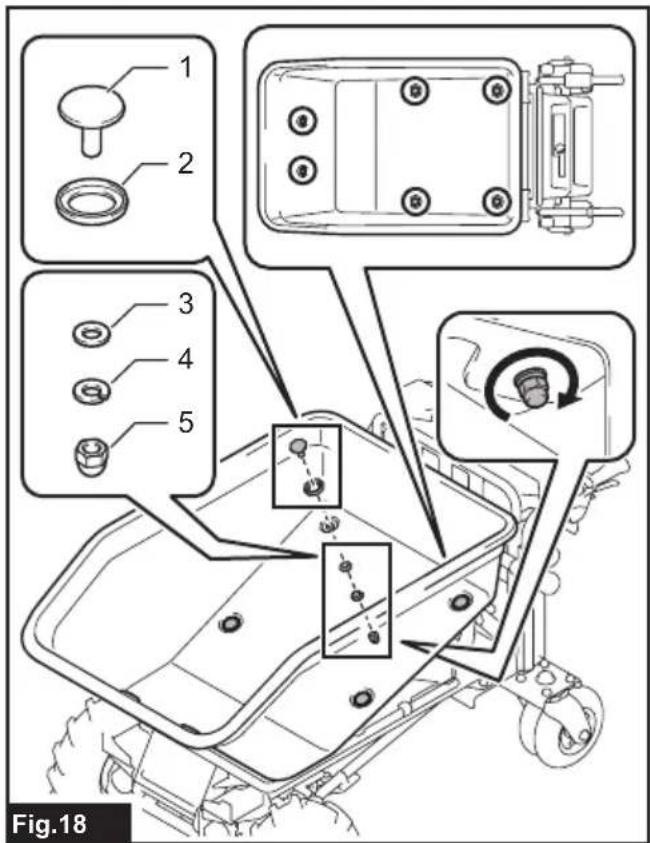
Place the rubber washer on the hole of the bucket and insert the bolt from the top. Attach the flat washer and spring washer in order to the bolt, and then tighten the nut from the bottom. Tighten the rest of the bolts and nuts in the same way.
▶ Fig.18: 1. Bolt 2. Rubber washer 3. Flat washer 4. Spring washer 5. Nut
- Securely tighten 4 bolts which were temporarily tightened in step 3.
Removing the bucket
To remove the bucket, perform the installation procedure in reverse.
Installing or removing the carrier
Optional accessory
Installing the carrier
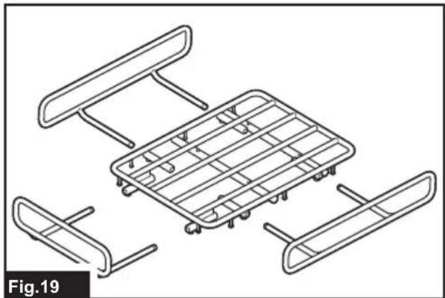
- Take out the carrier from the box, and attach the side rails and front rail to the base frame.
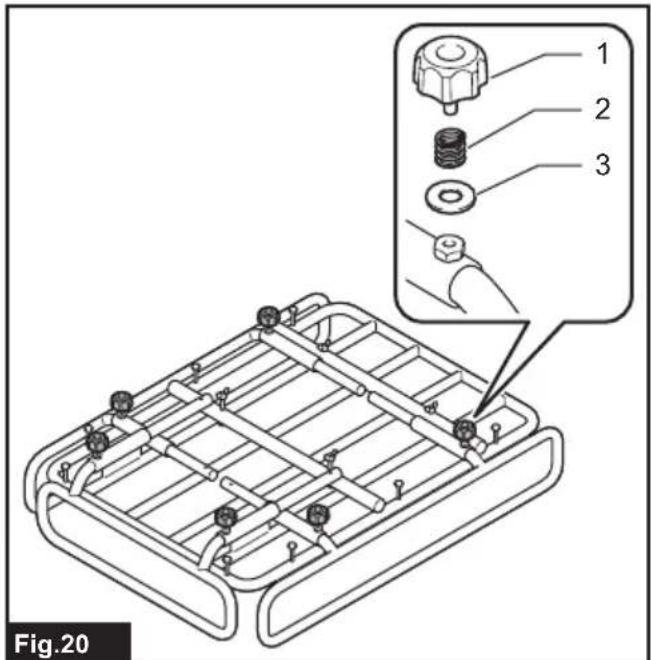
▶ Fig.19 - Tighten 6 thumb nuts together with springs and washers to fix the rails.
▶ Fig.20: 1. Thumb nut 2. Spring 3. Washer - Place the carrier on the dump unit.
Insert the bolt from the top. Attach the flat washer and spring washer in order to the bolt, and then tighten the nut from the bottom. Tighten the rest of the bolts and nuts in the same way.
▶ Fig.21: 1. Bolt 2. Flat washer 3. Spring washer 4. Nut
Removing the carrier
To remove the carrier, perform the installation procedure in reverse.
Installing or removing the flat bucket
Optional accessory
Installing the flat bucket
- Take out the flat bucket and holding frames from the box.
▶ Fig.22: 1. Flat bucket 2. Holding frame - Assemble the holding frames by tightening 12 bolts.
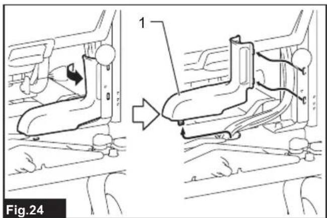
▶ Fig.23: 1. Bolt - Remove the cord cover located in the lower right corner on the rear of the machine.
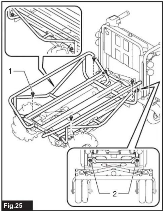
▶ Fig.24: 1. Cord cover - Place the holding frames on the base unit, and then temporarily tighten 2 bolts at the rear of the machine. Tighten the rest of 4 bolts securely, and then tighten 2 bolts at the rear of the machine securely.
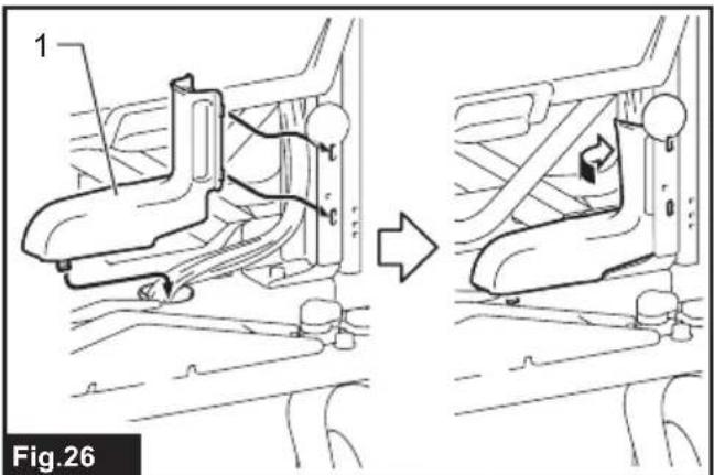
▶ Fig.25: 1. Bolt (front) 2. Bolt (rear) - Attach the cord cover.
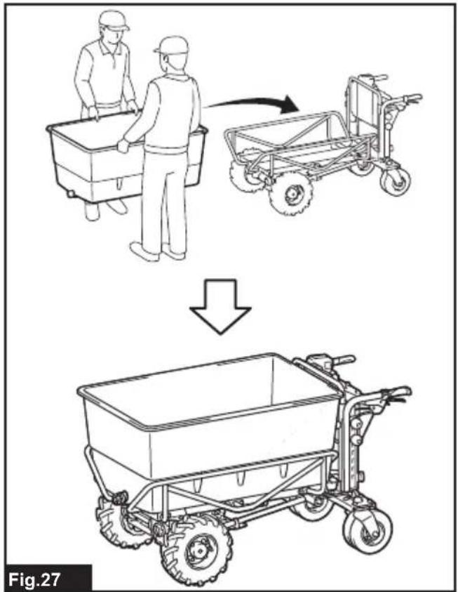
▶ Fig.26: 1. Cord cover - Hold the long sides of the flat bucket with two people as shown in the figure, and mount the flat bucket to the holding frames.
▶ Fig.27
Removing the flat bucket
To remove the flat bucket, perform the installation procedure in reverse.
FUNCTIONAL DESCRIPTION
Installing or removing battery cartridge
⚠️CAUTION: Always switch off the machine and lock the brake lever before installing or removing of the battery cartridge.
⚠CAUTION: Always install the battery cartridge fully until the red indicator cannot be seen. If not, it may accidentally fall out of the machine, causing injury to you or someone around you.
⚠️CAUTION: Do not install the battery cartridge forcibly. If the cartridge does not slide in easily, it is not being inserted correctly.
⚠️CAUTION: Do not use the high-temperature battery cartridge. When the high-temperature battery cartridge is used, the machine stops automatically before a short beep sound is emitted, and may cause an injury.
⚠️CAUTION: Be careful not to pinch your fingers when opening or closing the battery cover.
NOTICE: Make sure that the cover of the battery box is closed securely before use. Otherwise, mud, dirt, or water may cause damage to the product or the battery cartridge.
Installing the battery cartridge
- Pull up the lock lever, and then open the cover of the battery box.
▶ Fig.28: 1. Cover 2. Lock lever - Align the tongue on the battery cartridge with the slot on the battery box, and then slide the cartridge until it locks in place with a little click.
▶ Fig.29: 1. Battery cartridge - Insert the lock key in the place shown in the figure as far as it will go, and turn it clockwise.
▶ Fig.30: 1. Lock key
NOTE: To turn the lock key, insert the lock key completely.
- Close the cover of the battery box.
▶ Fig.31: 1. Cover
Removing the battery cartridge
- Pull up the lock lever, and then open the cover of the battery box.
- Pull out the battery cartridge from the battery box while sliding the button on the front of the cartridge.
▶ Fig.32: 1. Button
- Turn the lock key counterclockwise, and pull it out.
- Close the cover of the battery box.
Machine / battery protection system
The machine is equipped with a machine/battery protection system. This system automatically cuts off power to the motor to extend machine and battery life. The machine will automatically stop during operation if the machine or battery cartridge is under one of the following conditions.
A short beep sound or long beep sound is emitted before the machine stops automatically. The battery indicators and lamps on the control panel blink while the beep sound is emitted.
NOTE: To cancel the beep sound, release the switch trigger and pull the brake lever.
Overload protection
When the machine/battery is operated in a manner that causes it to draw an abnormally high current, the machine automatically stops and the main power lamp blinks in green. In this situation, turn the machine off and stop the application that caused the machine to become overloaded such as reducing the loaded objects. Then turn the machine on to restart.
Overheat protection
When the machine is overheated, the machine stops automatically and the main power lamp lights up in red. In this case, let the machine and battery cool before turning the machine on again.
Overdischarge protection
When the battery capacity is not enough, the main power lamp and the corresponding battery indicator blink in red. In this case, switch the battery cartridges, or change the battery cartridges to fully charged ones, or remove the battery cartridges from the machine and charge them.
NOTE: The main power lamp blinks in red when the battery is overheated.
Protections against other causes
NOTICE: The main power lamp blinks in green and red alternately when the abnormality occurs in the machine. In this case, refer to the section for troubleshooting.
Protection system is also designed for other causes that could damage the machine and allows the machine to stop automatically. Take all the following steps to clear the causes, when the machine has been brought to a temporary halt or stop in operation.
- Turn the machine off, and then turn it on again to restart.
- Charge the battery(ies) or replace it/them with recharged battery(ies).
- Let the machine and battery(ies) cool down.
NOTICE: If no improvement can be found or the machine stops due to a cause not described above, refer to the section for troubleshooting.
Indicating the remaining battery capacity
⚠️CAUTION: Before checking the remaining battery capacities or switching the battery cartridges, be sure to stop the machine.
⚠️CAUTION: When the battery capacity becomes low, a short beep sound is emitted. In this case, lock the brake lever, and then switch the battery cartridges to charged ones or charge the battery cartridges. If you continue to operate the machine at low battery capacity and the remaining battery capacity runs out, a long beep sound is emitted and the machine automatically stops and this may cause an accident or injury.
⚠️CAUTION: If the beep sound is emitted while operating on slopes, move the machine to a safe place, lock the brake lever, and then switch the battery cartridges to charged ones or charge the battery cartridges.
⚠️CAUTION: If the load is large and the beep sound is emitted while operating on slopes, lock the brake lever and pay attention to safety and switch the battery cartridges to charged ones. Move the machine to a safe place and lock the brake lever. Reduce the load before operating the machine again. For details, refer to the section for troubleshooting.
Checking the battery level on the battery box
▶ Fig.33: 1. Battery indicator 2. Check button
Press the check button to indicate the remaining battery capacities. The battery indicators correspond to each battery.
| Battery indicator status Remaining | battery capacity | ||
| On | Blinking | Off | |
 | 50% - 100% | ||
 | 20% - 50% | ||
 | 0% - 20% | ||
 | Empty | ||
 | Battery not installed | ||
NOTE: If you continue to pull the switch trigger even if you hear the short beep sound, the machine stops automatically. After the machine stops automatically, the beep sound continues and the support brake is enabled. To cancel the beep sound and release the support brake, release the switch trigger and pull the brake lever. Do not push the machine forcibly without releasing the support brake.
NOTE: You can check the remaining battery capacity even if the lock key is not inserted.
NOTE: The battery indicators for remaining battery capacity is just for a reference. The actual battery capacity may differ depending on the usage conditions.
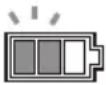
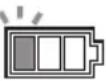
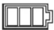
Checking the battery level on the battery cartridge
Only for battery cartridges with the indicator
▶ Fig.34: 1. Indicator lamps 2. Check button
Press the check button on the battery cartridge to indicate the remaining battery capacity. The indicator lamps light up for a few seconds.
| Indicator lamps Remaining | capacity | ||
| Lighted Off | Blinking | ||
 | 75% to 100% | ||
 | 50% to 75% | ||
 | 25% to 50% | ||
 | 0% to 25% | ||
 | Charge the battery. | ||
 + +  | The battery may have malfunctioned. | ||
NOTE: Depending on the conditions of use and the ambient temperature, the indication may differ slightly from the actual capacity.
NOTE: The first (far left) indicator lamp will blink when the battery protection system works.
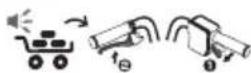
Switching the battery cartridge
▶ Fig.35: 1. Battery selection switch
The machine uses 2 battery cartridges for operation at a time. Up to 4 battery cartridges can be installed to the machine. Before operating the machine, select the battery cartridges used for operation by turning the battery selection switch.
NOTICE: If the battery cartridge is in the following condition, the machine does not work even if you switch the battery with the battery selection switch.
- The remaining capacity of at least one of the battery cartridges is empty.
- At least one of the battery cartridges is overheated.
In this case, remove the empty or overheated battery cartridge, or replace the battery cartridge with a charged one.
NOTE: If only 2 battery cartridges are installed to the machine, be sure to select the installed battery cartridges with the battery selection switch.
Control panel
⚠️CAUTION: Always lock the brake lever and turn off the machine when not in use.
Power button
▶ Fig.36: 1. Main power lamp 2. Power button
To turn on the machine, lock the brake lever and release the switch trigger, and then press the power button. The main power lamp lights up in green. To turn off the machine, lock the brake lever, and then press the power button.
NOTE: An electrical test is performed the first time the machine is driven after the machine is turned on. If a problem is detected, the main power lamp blinks in red or green alternately. In this case, refer to the section for troubleshooting.
NOTE: If the main power lamp lights up in red or blinks in red or green, refer to the instructions for machine/battery protection system or the section for troubleshooting.
NOTE: This machine employs the auto power-off function. To avoid unintentional start up, the machine will automatically shut down when the machine is stopped and not operated for a certain period after the machine is turned on.
NOTE: If you press the power button while pulling the switch trigger, the machine does not turn on. Release the switch trigger, and then press the power button.
Forward/reverse and speed button
▶ Fig.37: 1. Forward/reverse button 2. Speed button Press the forward/reverse button to switch between the forward mode and reverse mode. Press the speed button to switch between low speed, medium speed, and high speed. When the power is turned on, the forward mode and low speed are set.
NOTE: The forward/reverse button is not available while pulling the switch trigger.
NOTE: A short beep sound comes out when operating the machine in reverse.
NOTE: The speed button is not available when operating the machine in reverse.
Beep button
When you press the beep button, the beep sound is emitted.
▶ Fig.38: 1. Beep button
NOTE: The beep button is available when the machine is turned on.
NOTE: The beep button is available even if the lock key is not inserted in the battery box.
Lighting up the lamps
Press the lamp button on the battery box to light up the front lamps and rear lamp. To turn off the lamps, press the lamp button again.
▶ Fig.39: 1. Lamp button 2. Front lamp
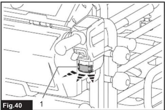
▶ Fig.40: 1. Rear lamp
NOTE: The lamps go off if the machine is not operated for a certain period.
NOTE: The lamps go off when the power is turned off.
NOTE: You can light up the lamps even if the lock key is not inserted.
Switch trigger and brake lever
CAUTION: Before installing the battery cartridge into the machine, always check to see that the switch trigger actuates properly and returns to the "OFF" position when released.
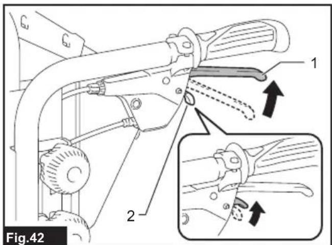
To start the machine, pull the switch trigger. Using the switch trigger, the speed can be adjusted within the set speed range. To stop the machine, release the switch trigger and pull the brake lever. To lock the brake lever, pull and hold the brake lever, then pull the lock lever, and then release the brake lever while pulling the lock lever. To release the lock, pull the brake lever.
▶ Fig.41: 1. Switch trigger
▶ Fig.42: 1. Brake lever 2. Lock lever
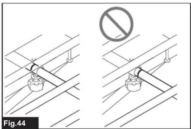
Adjusting the width of the carrier
NOTICE: Make sure that the side rails and front rail are fixed securely after tightening the thumb nuts.
Loosen 6 thumb nuts, and then slide the side rails and front rail. Tighten the thumb nuts to fix the side rails and front rail.
▶ Fig.43: 1. Thumb nut 2. Rail
⚠️CAUTION: Do not slide the rails beyond the limit mark.
▶ Fig.44
Adjusting the handle height
NOTICE: Fix the left and right handles at the same height.
The handle height can be adjusted in 7 levels. To adjust the handle height, loosen 2 knobs, then adjust the handle height by aligning the hole on the handle with the protrusion on the rear frame, and then tighten 2 knobs securely. Adjust the height of the other handle in the same way.
▶ Fig.45: 1. Knob
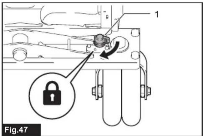
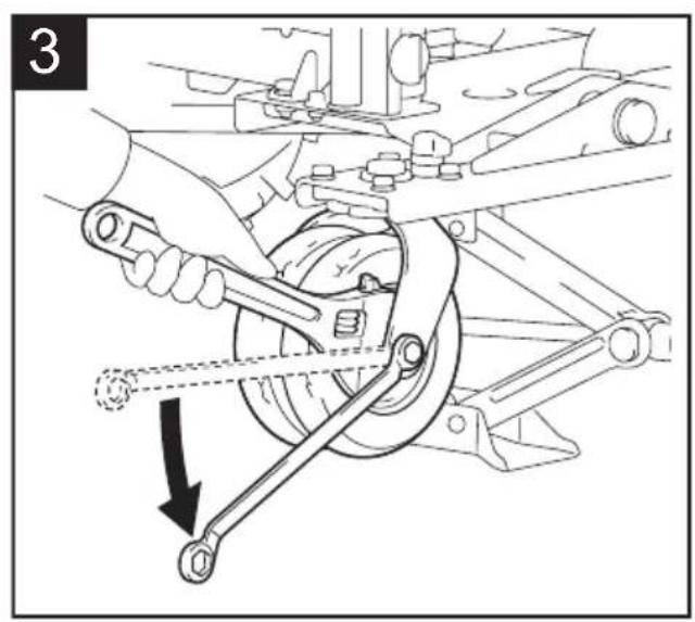
Rear wheel lock
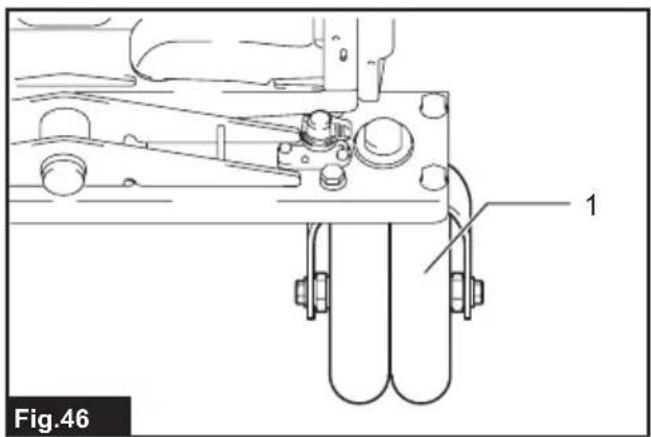
You can fix the direction of the rear wheels using the rear wheel lock.
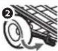
- Slightly move the machine forward so that the rear wheels face the direction shown in the figure.
▶ Fig.46: 1. Rear wheel - Rotate the rear wheel lock toward the rear.
▶ Fig.47: 1. Rear wheel lock - Lock the other rear wheel in the same way.
- Move the rear wheel back and forth or left and right slightly to make sure it is locked.
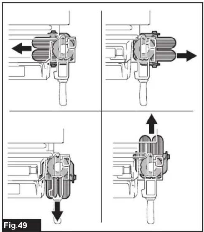
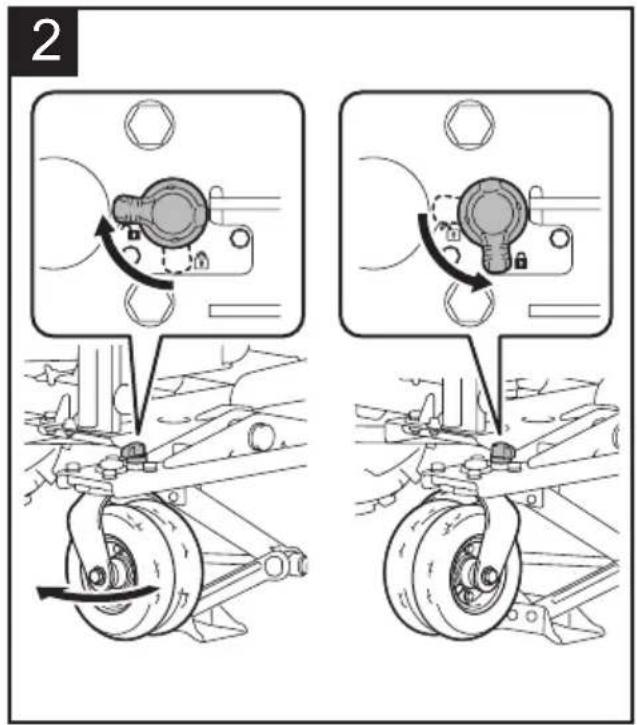
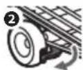
To release the rear wheel lock, rotate the rear wheel lock 90° as shown in the figure.
▶ Fig.48: 1. Rear wheel lock
NOTE: The rear wheels can be fixed in 4 different directions as shown in the figure.
▶ Fig.49
Using the level
Using the level, you can check if the ground is level.
▶ Fig.50: 1. Level
OPERATION
CAUTION: Be sure to lock the brake lever before loading, unloading, and dumping objects, or draining liquid.
Operating the machine
NOTICE: Be sure to insert the lock key before the operation. If the lock key is not inserted, a beep sound is emitted when you pull the switch trigger. The beep sound stops by releasing the switch trigger and pulling the brake lever.
NOTICE: Perform the inspection before operating the machine by referring to the section for maintenance.
- Make sure that the brake lever is locked. Install the battery cartridges, and insert the lock key and turn it clockwise.
- Select the battery cartridges with the battery selection switch.
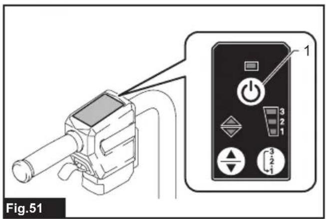
- Press the power button on the control panel to turn the power on.
▶ Fig.51: 1. Power button
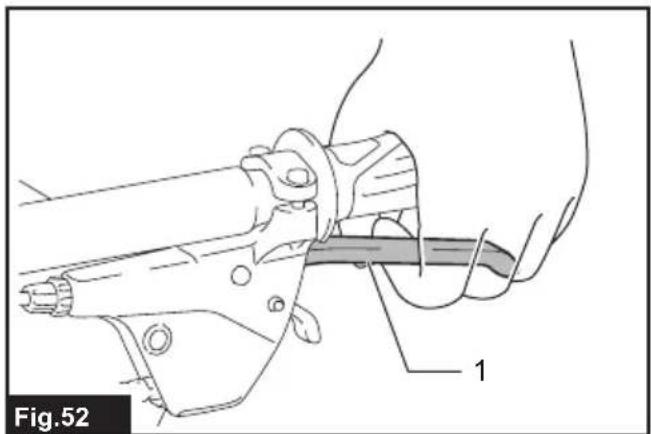
- Pull the brake lever to release the lock of the brake lever.
▶ Fig.52: 1. Brake lever - Hold the handles firmly with both hands.
▶ Fig.53 - Pull the switch trigger.
▶ Fig.54: 1. Switch trigger
Loading objects
⚠️ CAUTION: Before loading objects on the machine, make sure that the machine is turned off and the brake lever is locked.
⚠️ CAUTION: Before loading objects on the machine, make sure that the dump unit is locked.
CAUTION: Be sure to load objects within the carrier, bucket, or flat bucket. If objects are sticking out of the carrier, bucket, or flat bucket, they may fall or collapse if they touch obstacles.
▶ Fig.55
CAUTION: Be sure to load objects so that they are below eye level. If the load is too high, it is dangerous because the view is obscured. Also, there is a risk of overturning and injury because the load is likely to be unbalanced.
▶ Fig.56
CAUTION: Do not load the objects beyond the height of the bucket or flat bucket. Loading the objects beyond the height of the bucket or flat bucket may cause the load to fall or collapse.
When loading objects on the carrier, secure the objects with ropes and tie them down to the rope hooks of the carrier.
▶ Fig.57: 1. Rope hook
Dumping objects
⚠️CAUTION: Before lifting the carrier or bucket, be sure to lock the brake lever.
⚠️CAUTION: Lift the carrier or bucket on flat and stable ground. Operation on unstable ground may cause an accident or injury.
⚠CAUTION: Keep the load to a minimum. If the load is large, do not try to lift the carrier or bucket. Reduce the load, and then lift the carrier or bucket.
⚠CAUTION: When lifting or returning the carrier or bucket, never insert or place a part of your body between the dump unit and the carrier or bucket.
⚠️CAUTION: If the load is fixed by ropes or other means, untie the load before lifting the dump unit.
⚠CAUTION: Before lifting the carrier or bucket, make sure that there are no people or obstacles around the machine.
You can dump the objects by lifting and tilting the carrier or bucket.
- Stop the machine, and then lock the brake lever.
NOTICE: It is recommended to chock the front wheels to stabilize the machine.
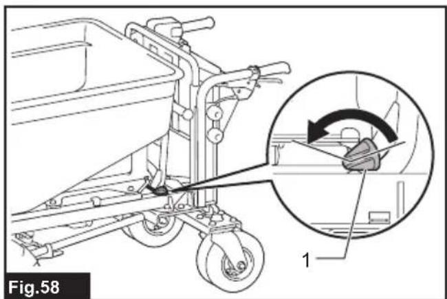
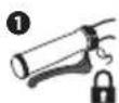
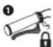
- Rotate the lock lever of dump unit toward the front of machine to unlock the dump unit.
▶ Fig.58: 1. Lock lever - Stand at the side of the machine, then hold the handle of the machine with one hand, and then hold the handle of the dump unit with the other hand.
▶ Fig.59
⚠️CAUTION: Hold the handles of the machine and dump unit firmly, and work in a stable posture.
- Tilt the carrier or bucket by lifting up the handle of the dump unit.
- Return the carrier or bucket, and then lock the dump unit by pulling down the handle of the dump unit.
⚠️CAUTION: After dumping loads, be sure to lock the dump unit by returning the dump unit to its original position.
Draining liquid
⚠️CAUTION: Before draining the liquid, be sure to lock the brake lever.
To drain the liquid inside of the flat bucket, loosen and remove the cap of the flat bucket. Tighten the cap after the draining.
▶ Fig.60: 1. Cap
NOTE: When removing the cap, be careful as the cap may be pushed out by the pressure of liquid. Be careful not to get the liquid on your face or other parts of your body.
MAINTENANCE
CAUTION: Always be sure to park the machine on flat ground and lock the brake lever before storage or attempting to perform inspections or maintenance.
CAUTION: Always be sure that the lock key and battery cartridge are removed from the machine before storage, inspections, or maintenance.
CAUTION: Always remove the lock key when the machine is not in use. Store the lock key in a safe place out of reach of children.
Inspection before operation
Perform the following inspections before operation the machine.
-
Check that the bolts, nuts, and knobs are tightened firmly.
▶ Fig.61 -
Check that the brake is working properly. If you feel the brake is not working sufficiently, perform the cleaning of the brake. If no improvement can be found, ask Makita Authorized Service Centers for repair.
- Check that the dump unit is locked when the handle of the dump unit is fully pulled down.
▶ Fig.62: 1. Handle
- Check that the tires of front and rear wheels are not damaged, and the air in the tires is sufficient.
- Check that the front lamps, rear lamp, and reflector are clean. Clean them if necessary.
- Check that the scrapers are in the correct position. If the scraper is facing upward, adjust the orientation of the scraper by loosing the bolts. When tightening the bolts, do not push the scraper toward the front of the machine.
▶ Fig.63: 1. Scraper
Cleaning the machine
NOTICE: Never use gasoline, benzine, thinner, alcohol or the like. Discoloration, deformation or cracks may result.
NOTICE: Do not use the high pressure washer for cleaning.
NOTICE: When cleaning the machine, be sure to close the cover of battery box. Otherwise, water may enter into the battery box, and cause a malfunction of machine.
Remove mud, dirt, and the like from the machine. Clean the machine with running water. After the cleaning, wipe the machine with a dry cloth.
Storage
Lock the brake lever, and remove the battery cartridges and lock key. Store the machine in a safe place out of the reach of children.
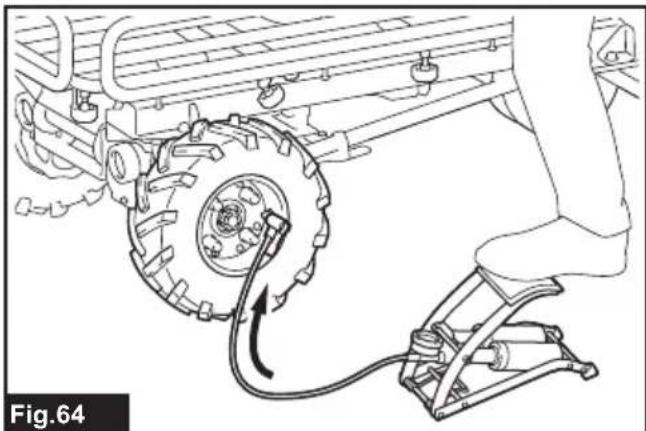
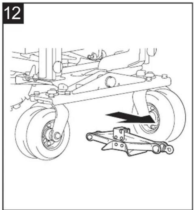
Refilling the tire with air
Check that the air in the tire for the front and rear wheels is not missing. If the air in the tire is insufficient, refill the tire with air using an inflator. The air pressure is as follows:
• Tire for front wheel: 280 kPa (40 PSI)
- Tire for rear wheel: 525 kPa (75 PSI)
Front wheel
▶ Fig.64
Rear wheel
▶ Fig.65
Replacing the tire
⚠️CAUTION: Before replacing the tires, be sure to unload all objects from the machine.
⚠️CAUTION: When replacing the tires, wear the gloves.
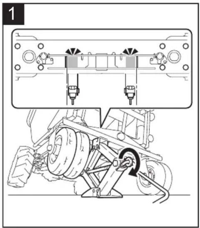
Replacing the tire of front wheel
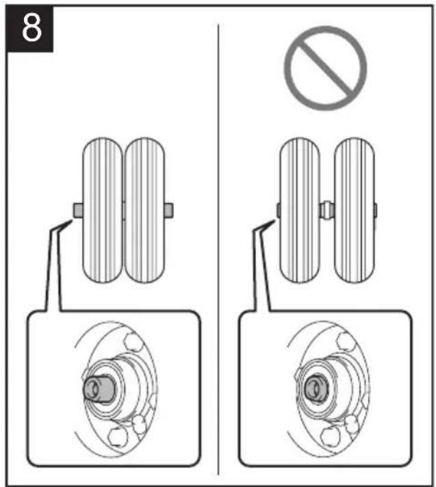
NOTE: When installing the gray tire, install it so that the valve faces outward.
▶ Fig.66
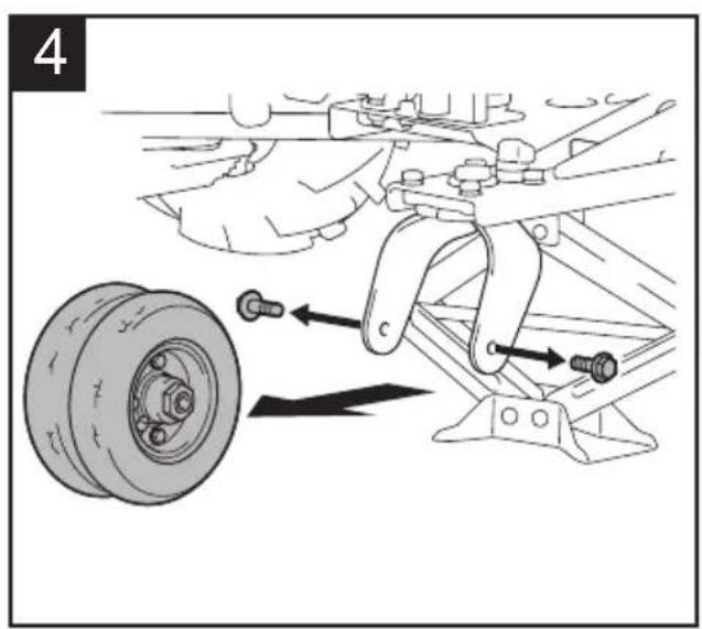
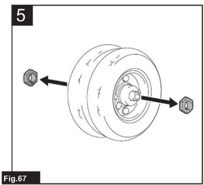
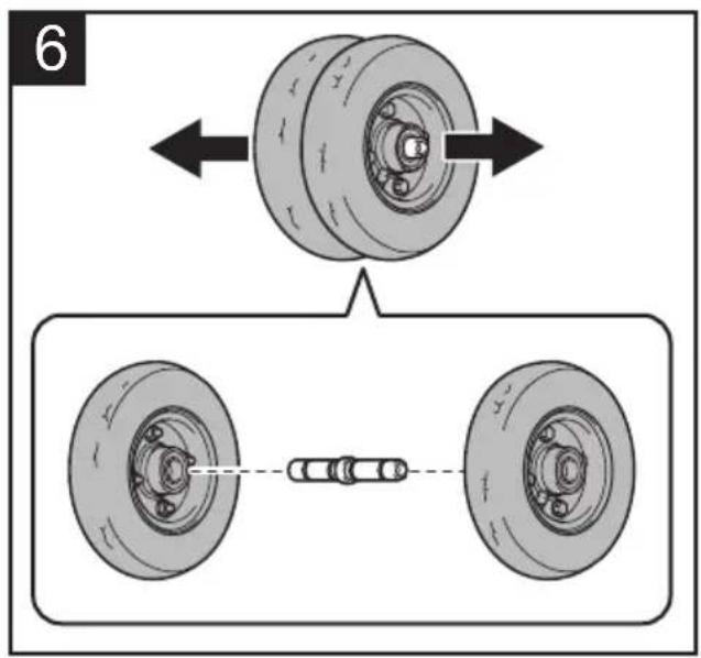
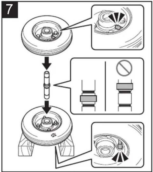
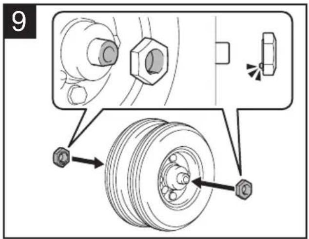
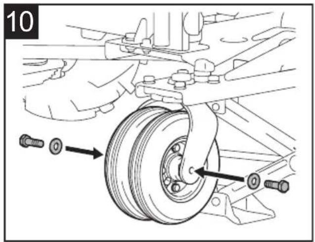
Replacing the tire of rear wheel
▶ Fig.67
▶ Fig.68
TROUBLESHOOTING
Before asking for repairs, conduct your own inspection first. If you find a problem that is not explained in the manual, do not disassemble the machine. Instead, ask Makita Authorized Service Centers, always using Makita replacement parts for repairs.
| State of abnormality | Main power lamp Cause Remedy | ||
| The machine does not turn on. | Turned off. Two battery cartridges are not installed. | Install two charged battery cartridges. | |
| Battery problem (under voltage) Recharge the battery cartridge. If recharging is not effective, replace battery cartridge. | |||
| Battery selection switch is not in the correct position. Select the correct battery using the battery selection switch. | |||
| The machine does not start. | The lamp blinks in red. Battery's charge level is low. Recharge the battery cartridge. If recharging is not effective, replace battery cartridge. | ||
| At least one of the battery is empty. Remove the empty battery, or replace it with charged one. In this case, the far left lamp of the battery indicator of the corresponding battery blinks. | |||
| The lamp blinks in green. | The lock key is not inserted. Insert the lock key and turn it clockwise. | ||
| The machine stopped due to overload. | Reduce the loaded objects. | ||
| The front or rear wheels are stuck or locked. | Remove the cause of stuck or locked wheels. | ||
| The lamp lights up in red. | The machine stopped due to overheat. | Cool down the machine and battery. | |
| The lamp blinks in red and green alternately. | The lock key is not inserted. Insert the lock key and turn it clockwise. | ||
| The machine detected an abnormality. | Turn off the machine, and then back on. | ||
| A malfunction of machine has occurred. Ask Makita Authorized Service Centers for repair. | |||
| The lamp lights up in green. | The neutral change lever is not in its original position. | Lock the brake lever, and then return the neutral change lever to its original position. | |
| The machine stops after a little use. | The lamp blinks in red. Battery's charge level is low. Recharge the battery cartridge. If recharging is not effective, replace battery cartridge. | ||
Troubleshooting for stop of machine
WARNING: Unless absolutely necessary, never disable the support brake of the machine with the neutral change lever. Since the support brake of the machine is disabled, the machine may move unintentionally and cause an accident or personal injury.
WARNING: Be sure to return the neutral change lever to its original position after pulling the lever outward.
If the machine cannot be moved when the batteries run out or a malfunction of machine has occurred, you can move the machine manually by pulling the neutral change lever outward to disable the support brake.
- Lock the brake lever.
- Unload all of the objects from the machine.
⚠️CAUTION: Be sure to unload all objects from the machine. The machine may move unintentionally if the objects are left on the machine.
- If the machine is on a slope, unlock the brake lever, and orient the machine so that the brake lever is on the upper side of the slope and the machine is parallel to the slope. Lock the brake lever.
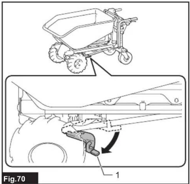
▶ Fig.69 - Make sure that the machine does not move, and pull out the neutral change lever outward.
▶ Fig.70: 1. Neutral change lever - Unlock the brake lever and move the machine manually to a safe place. Since the support brake is disabled, move the machine carefully with the brake lever so that the speed does not increase.
- After moving the machine to a safe place, lock the brake lever.
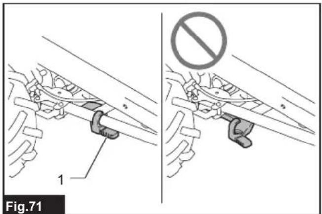
- Return the neutral change lever to its original position. Make sure that the neutral change lever is fully returned as shown in the figure.
▶ Fig.71: 1. Neutral change lever
OPTIONAL ACCESSORIES
CAUTION: These accessories or attachments are recommended for use with your Makita machine specified in this manual. The use of any other accessories or attachments might present a risk of injury to persons. Only use accessory or attachment for its stated purpose.
CAUTION: Only use the Makita accessory or attachment for the machine. Use of any other accessory or attachment may result in serious personal injury.
If you need any assistance for more details regarding these accessories, ask your local Makita Service Center.
- Carrier
- Bucket
- Flat bucket
- Dump unit
- Front tire (black)
- Front tire (gray)
- Rear tire (gray)
- Makita genuine battery and charger
NOTE: Some items in the list may be included in the tool package as standard accessories. They may differ from country to country.
SPÉCIFICATIONS
▶ Fig.10: 1. Poignée
▶ Fig.31: 1. Couvercle
⚠ WAARSCHUWING: Draag gehoorbescherming.
VEILIGHEIDSWAAR- SCHUWINGEN
▶ Fig.18: 1. Bout 2. Rubber ring 3. Platte ring 4. Veerring 5. Moer
▶ Fig.21: 1. Bout 2. Platte ring 3. Veerring 4. Moer
▶ Fig.38: 1. Pieptoonknop
▶ Fig.50: 1. Waterpas
BEDIENING
OPTIONELE ACCESSOIRES
▶ Fig.13: 1. Bolt (front) 2. Bolt (bag)
▶ Fig.17: 1. Stiver 2. Bolt
▶ Fig.25: 1. Bolt (front) 2. Bolt (bag)

- Symbols
- Intended use
- Noise
- Vibration
- Declarations of Conformity
- SAFETY WARNINGS
- General power tool safety warnings
- Save all warnings and instructions for future reference.
- Battery powered wheelbarrow safety warnings
- Preparation
- Operation
- Operation on slopes
- Loading objects
- Transportation of machine
- Maintenance and storage
- Battery tool use and care
- Electrical and battery safety
- SAVE THESE INSTRUCTIONS.
- Important safety instructions for battery cartridge
- ⚠️CAUTION: Only use genuine Makita batteries.
- Tips for maintaining maximum battery life
- PARTS DESCRIPTION
- DCU603
- DCU604
- DCU605
- CONFIGURATION OF MACHINE
- When the bucket is installed
- When the carrier is installed
- When the flat bucket is installed
- ASSEMBLY
- Installing or removing the dump unit
- Installing the dump unit
- Removing the dump unit
- Installing or removing the bucket
- Installing the bucket
- Removing the bucket
- Installing or removing the carrier
- Installing the carrier
- Removing the carrier
- Installing or removing the flat bucket
- Installing the flat bucket
- Removing the flat bucket
- FUNCTIONAL DESCRIPTION
- Installing or removing battery cartridge
- Installing the battery cartridge
- Removing the battery cartridge
- Machine / battery protection system
- Overload protection
- Overheat protection
- Overdischarge protection
- Protections against other causes
- Indicating the remaining battery capacity
- Checking the battery level on the battery box
- Checking the battery level on the battery cartridge
- Switching the battery cartridge
- Control panel
- Power button
- Forward/reverse and speed button
- Beep button
- Lighting up the lamps
- Switch trigger and brake lever
- Adjusting the width of the carrier
- Adjusting the handle height
- Rear wheel lock
- Using the level
- Operating the machine
- Dumping objects
- Draining liquid
- MAINTENANCE
- Inspection before operation
- Cleaning the machine
- Storage
- Refilling the tire with air
- Replacing the tire
- Replacing the tire of front wheel
- Replacing the tire of rear wheel
- TROUBLESHOOTING
- Troubleshooting for stop of machine
- OPTIONAL ACCESSORIES
- VEILIGHEIDSWAAR- SCHUWINGEN
- BEDIENING
- OPTIONELE ACCESSOIRES
Brand : MAKITA
Model : DCU604
Category : Electric wheelbarrow