DCU180Z - Electric wheelbarrow MAKITA - Free user manual and instructions
Find the device manual for free DCU180Z MAKITA in PDF.
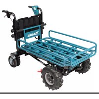
| Product type | Electric wheelbarrow |
| Brand | Makita |
| Model | DCU180Z |
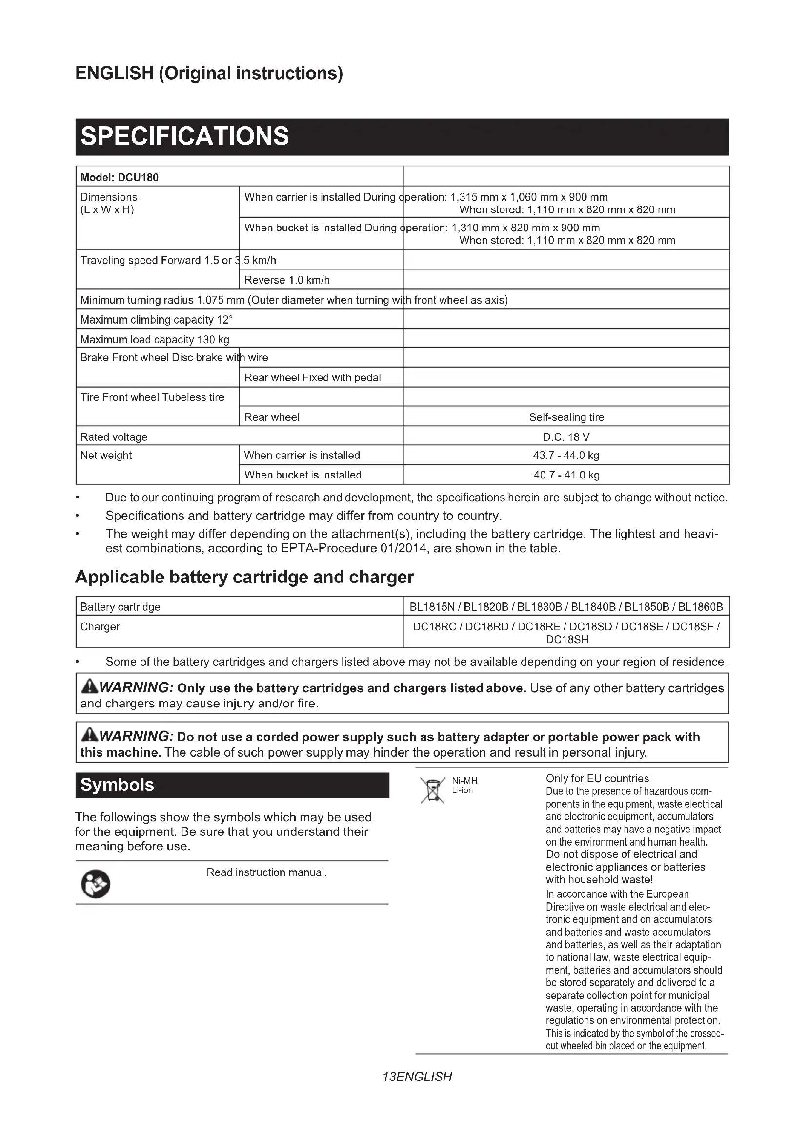
| Dimensions (trolley installed) - operation | 1 315 mm x 1 060 mm x 900 mm |
| Dimensions (trolley installed) - storage | 1 110 mm x 820 mm x 820 mm |
| Dimensions (tub installed) - operation | 1 310 mm x 820 mm x 900 mm |
| Dimensions (tub installed) - storage | 1 110 mm x 820 mm x 820 mm |
| Net weight (with trolley) | 43,7 - 44,0 kg |
| Net weight (with tub) | 40,7 - 41,0 kg |
| Maximum payload | 130 kg |
| Travel speed - forward | 1,5 or 3,5 km/h |
| Travel speed - reverse | 1,0 km/h |
| Minimum turning radius | 1 075 mm |
| Maximum slope capability | 12° |
| Power supply | 18 V DC (Li-ion battery) |
| Compatible batteries | BL1815N, BL1820B, BL1830B, BL1840B, BL1850B, BL1860B |
| Compatible chargers | DC18RC, DC18RD, DC18RE, DC18SD, DC18SE, DC18SF, DC18SH |
| Front wheel brake | Disc brake with cable |
| Rear wheel brake | Pedal lock |
| Front wheel tire | Tubeless |
| Rear wheel tire | Self-sealing |
| Sound pressure level (LpA) | 70 dB(A) or less |
| Vibration level (no load operation) | 2,5 m/s² or less |
| Maintenance and cleaning | Clean with running water, wipe dry; periodic check of bolts, brakes, and tire |
| Safety | Use on flat ground, do not overload, do not use on public roads, lock brake before any intervention |
| Spare parts and repairability | Optional accessories: trolley, tub, auxiliary wheels; genuine Makita batteries and chargers |
Frequently Asked Questions - DCU180Z MAKITA
User questions about DCU180Z MAKITA
0 question about this device. Answer the ones you know or ask your own.
Ask a new question about this device
Download the instructions for your Electric wheelbarrow in PDF format for free! Find your manual DCU180Z - MAKITA and take your electronic device back in hand. On this page are published all the documents necessary for the use of your device. DCU180Z by MAKITA.
USER MANUAL DCU180Z MAKITA
| EN | Battery Powered Wheelbarrow | INSTRUCTION MANUAL 13 |
| FR | Brouette À Batterie MANUEL D’INSTRUCTIONS 23 | |
| DE | Akku-Schubkarre BETRIEBSANLEITUNG 35 | |
| IT | Carriola elettrica a batteria ISTRUZIONI PER L’USO 47 | |
| NL | Accuaangedreven kruiwagen GEBRUIKSAANWIJZING 59 | |
| ES | Carretilla Propulsada a Batería | MANUAL DE INSTRUCCIONES 71 |
| PT | Carrinho de Mão a Bateria MANUAL DE INSTRUÇÕES 83 | |
| DA | Batteridrevet trillebør BRUGSANVISNING 95 | |
| EL | Καρότσι με μπαταρία ΕΓΧΕΙΡΙΔΙΟ ΟΔΗΓΙΩΝ 106 | |
| TR | Akülü El Arabası | KULLANMA KILAVUZU 118 |
DCU180
natural_image
Line drawings of two different agricultural tools: a two-wheeled cart and a four-wheeled wheelbarrow (no text or symbols present)
text_image
1 2 3 4 5 2 6 7 986 Fig.1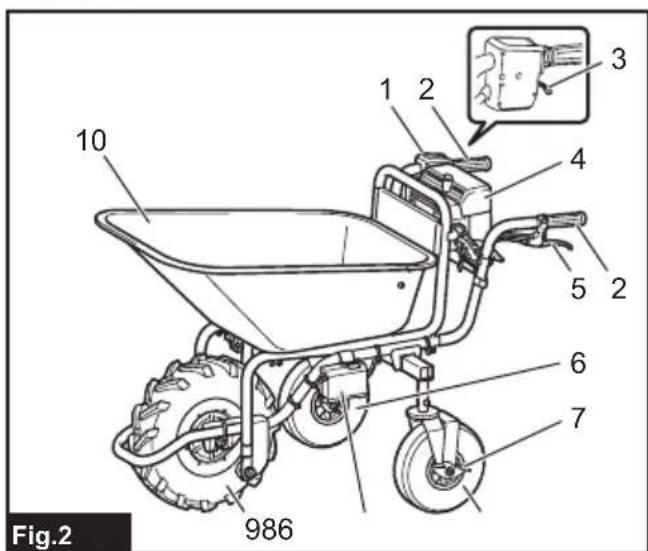
text_image
10 1 2 4 5 2 6 7 986 Fig.2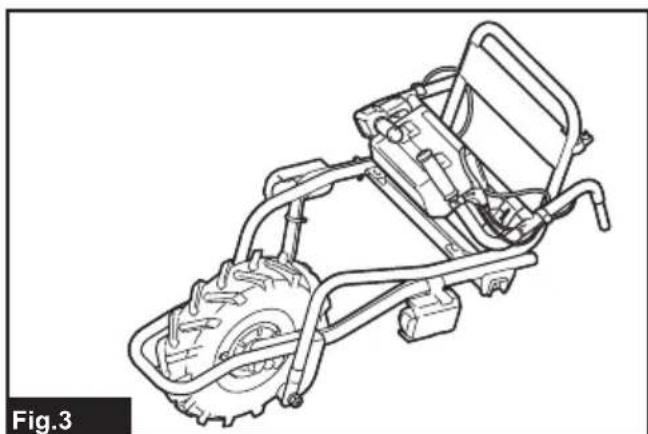
natural_image
Technical line drawing of a mechanical vehicle chassis with visible motors and suspension components (no text or symbols)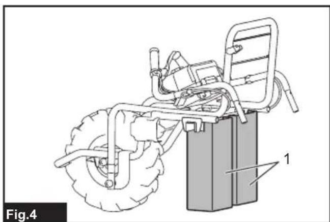
natural_image
Line drawing of a vehicle chassis with large tires and a battery, labeled 'Fig.4' (no text or symbols on the diagram itself)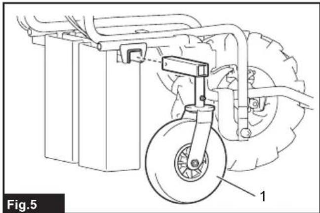
natural_image
Technical line drawing of a mechanical assembly with a wheel and attached components (no text or symbols)
natural_image
Technical line drawing of a mechanical assembly with labeled components (no text or symbols beyond label)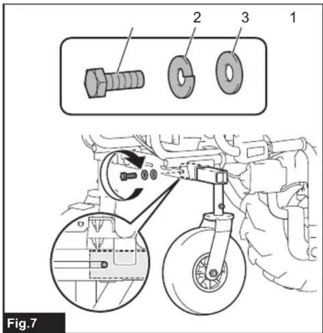
text_image
Fig.7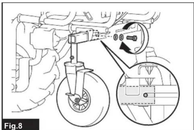
text_image
Fig.8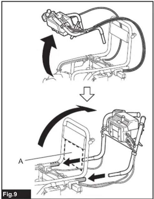
text_image
Fig.9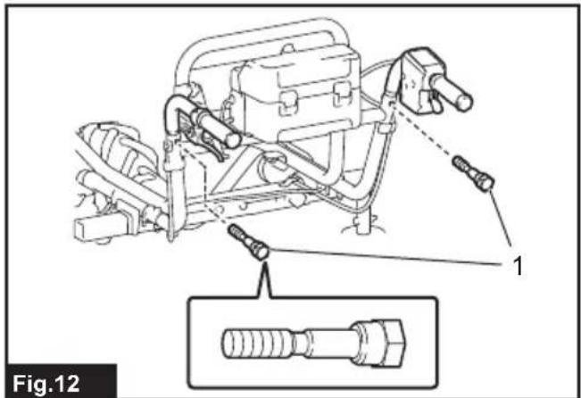
text_image
Fig.12
text_image
Fig.13
text_image
Fig.10
text_image
Fig.14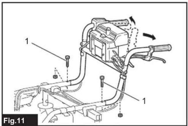
text_image
Fig.11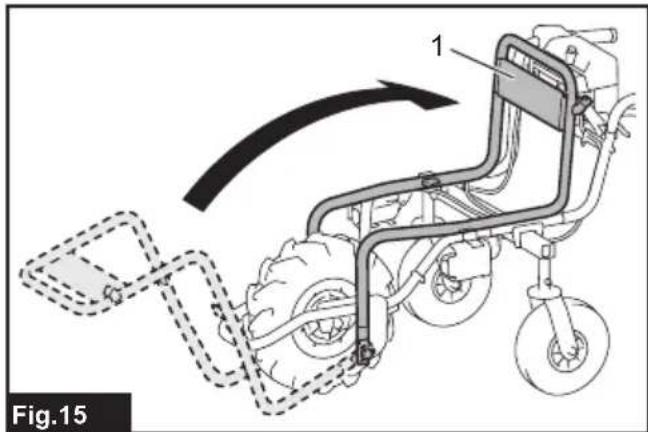
text_image
Fig.15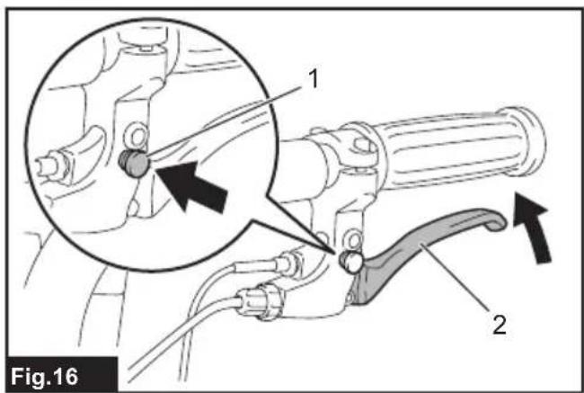
text_image
Fig.16 1 2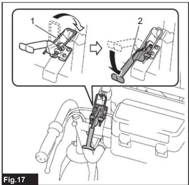
text_image
1 2 Fig.17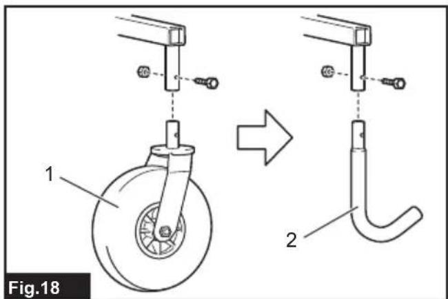
text_image
Fig.18 1 2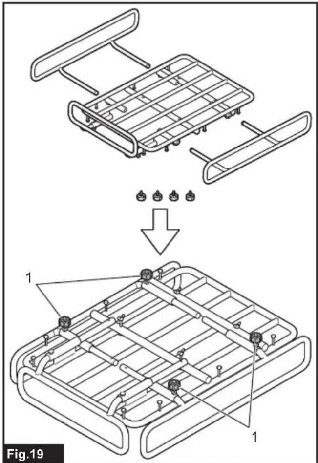
text_image
Fig.19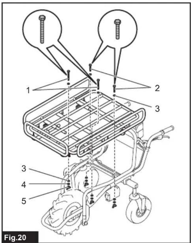
text_image
1 2 3 3 4 5 Fig.20
text_image
1 2 3 4 Fig.21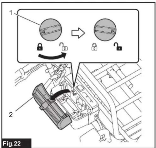
text_image
1 2 Fig.22
text_image
1 Fig.23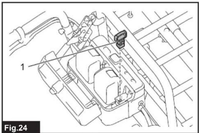
text_image
1 Fig.24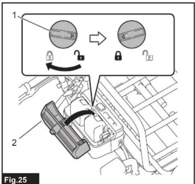
text_image
1 2 Fig.25
text_image
1 Fig.26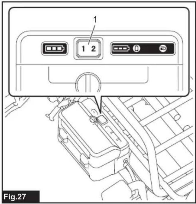
text_image
1 1 2 Fig.27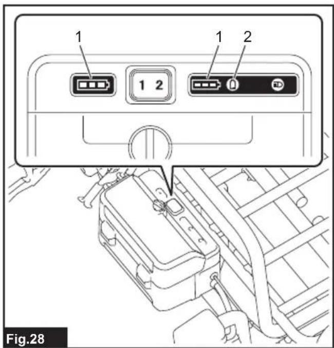
text_image
1 1 2 1 2 Fig.28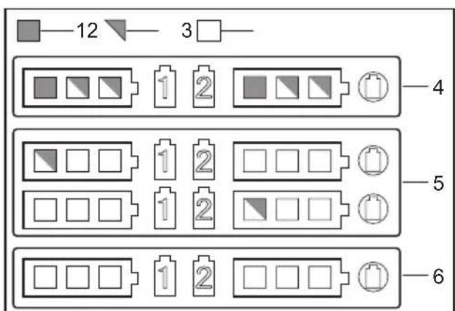
text_image
12 3 4 5 6Fig.29

text_image
Fig.30 1 2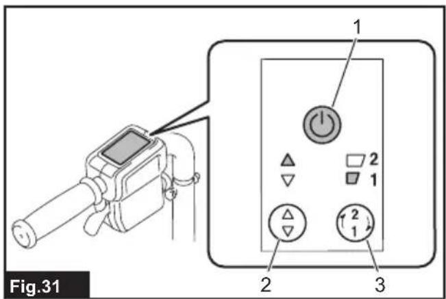
text_image
Fig.31 1 2 3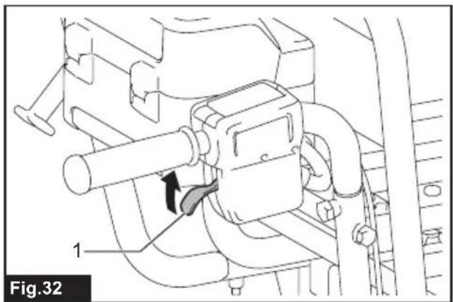
natural_image
Technical line drawing of a mechanical device with labeled parts and directional arrow (no text or symbols beyond labels)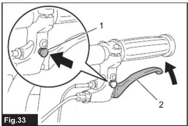
text_image
Fig.33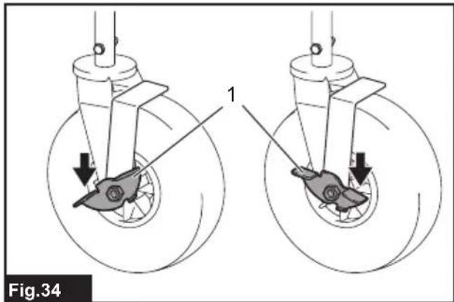
text_image
Fig.34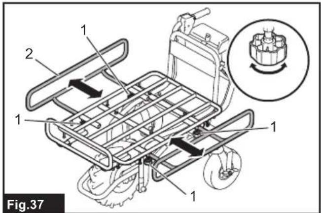
text_image
1 2 1 1 1 Fig.37
text_image
1 2 0 D 1 2 2 Fig.35
text_image
✓ No Fig.38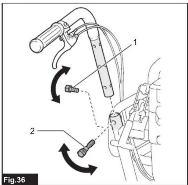
text_image
Fig.36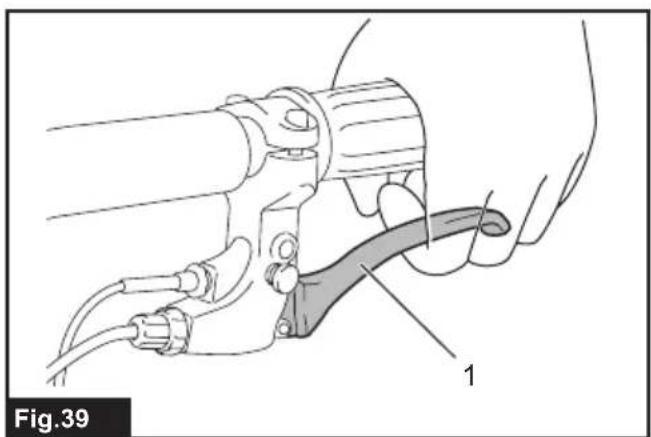
natural_image
Technical diagram of a mechanical device with labeled component '1' (no text or symbols beyond label)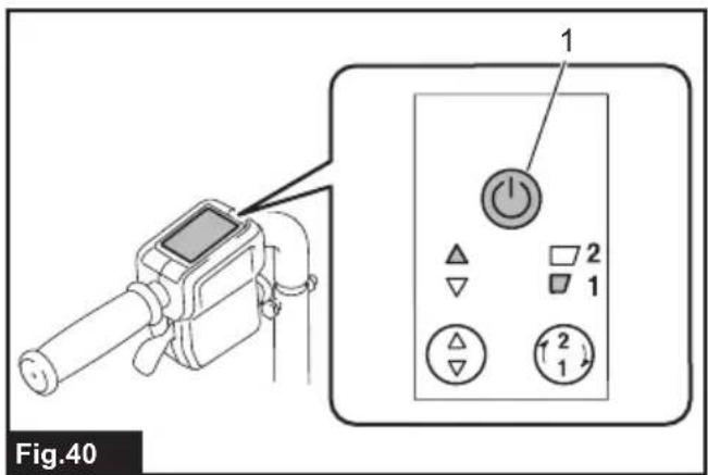
text_image
Fig.40 1 2 1 2 1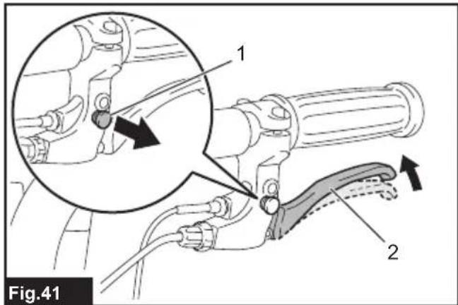
text_image
Fig.41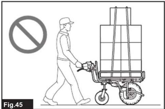
natural_image
Illustration of a worker pushing a pallet cart with a no-smoking symbol (no text or labels)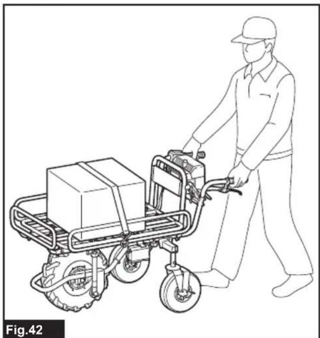
natural_image
Line drawing of a worker pushing a two-wheeled cart with boxes (no text or symbols)
natural_image
Line drawing of a worker pushing a two-wheeled cart loaded with boxes (no text or symbols)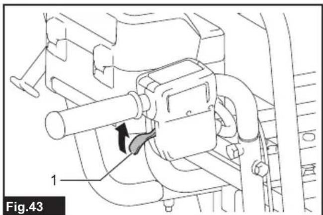
natural_image
Technical line drawing of a mechanical device with labeled component 1, showing internal components and directional arrow (no text or symbols beyond label)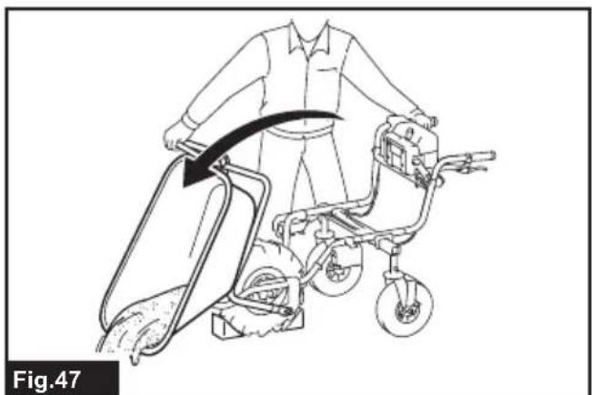
natural_image
Line drawing of a person using a tricycle with a belt, showing motion and safety instructions (no text or symbols)
natural_image
Illustration of a worker pushing a cart with a no-smoking symbol (no text or labels present)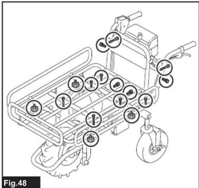
text_image
Fig.48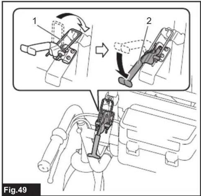
text_image
1 2 Fig.49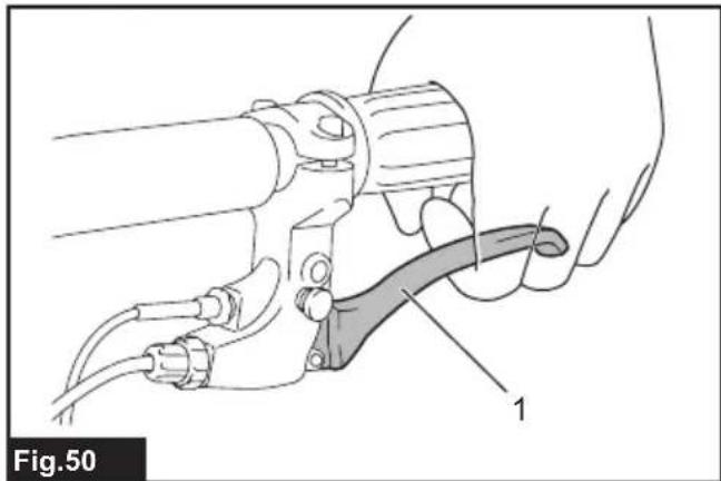
natural_image
Technical line drawing of a hand holding a tool with a curved handle, labeled 'Fig.50' (no text or symbols on the diagram itself)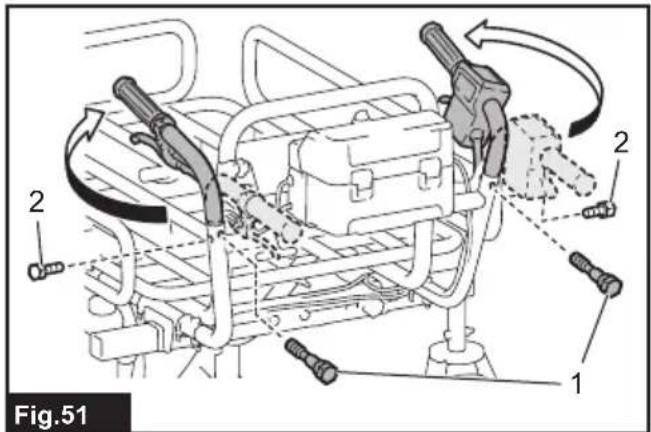
text_image
Fig.51 1 2 2 2
text_image
1 Fig.52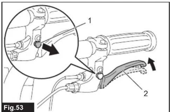
text_image
Fig.53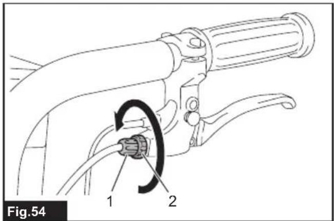
text_image
Fig.54 1 2
text_image
Fig.55
text_image
1 Fig.57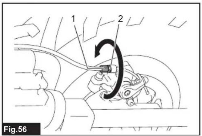
text_image
1 2 Fig.56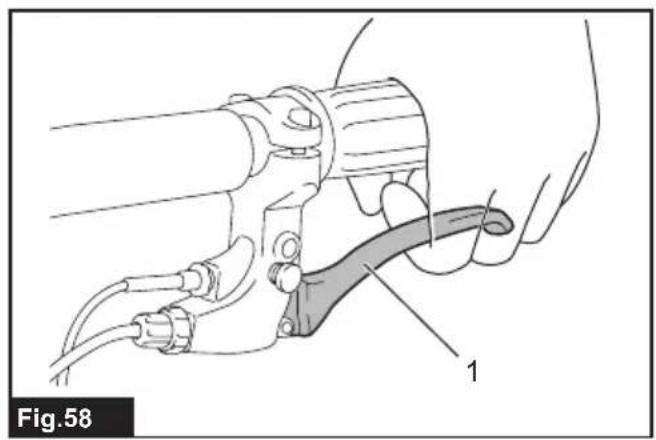
natural_image
Technical line drawing of a mechanical device with labeled component '1' (no text or symbols beyond label)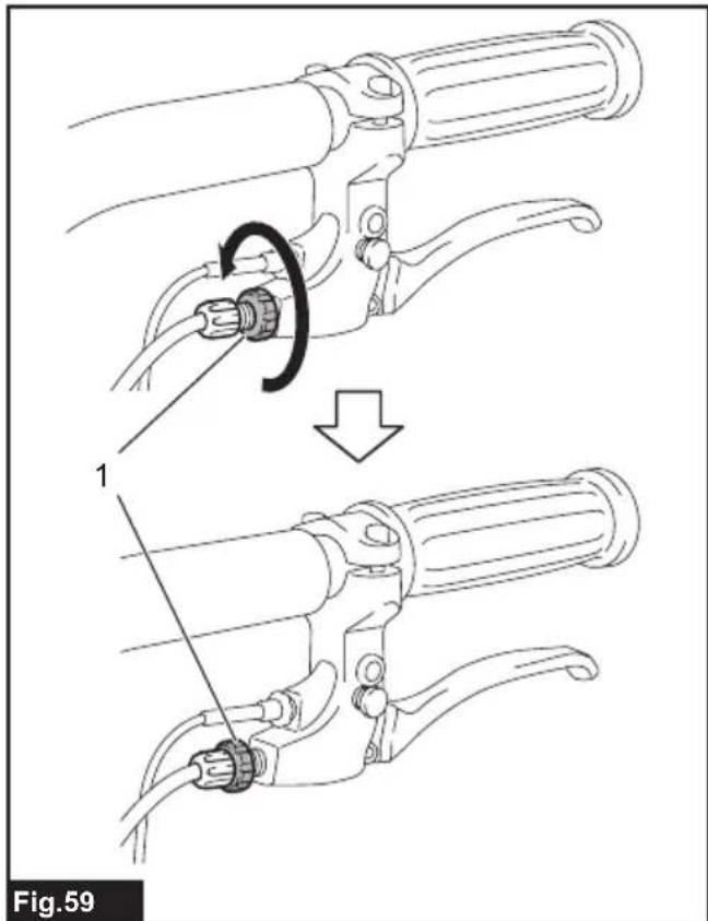
text_image
Fig.59
natural_image
Illustration of a mechanical device being adjusted for a cable, showing motion and assembly steps (no text or symbols)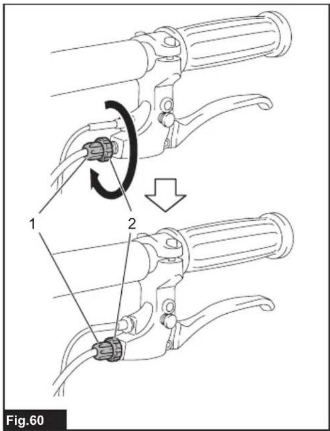
text_image
Fig.60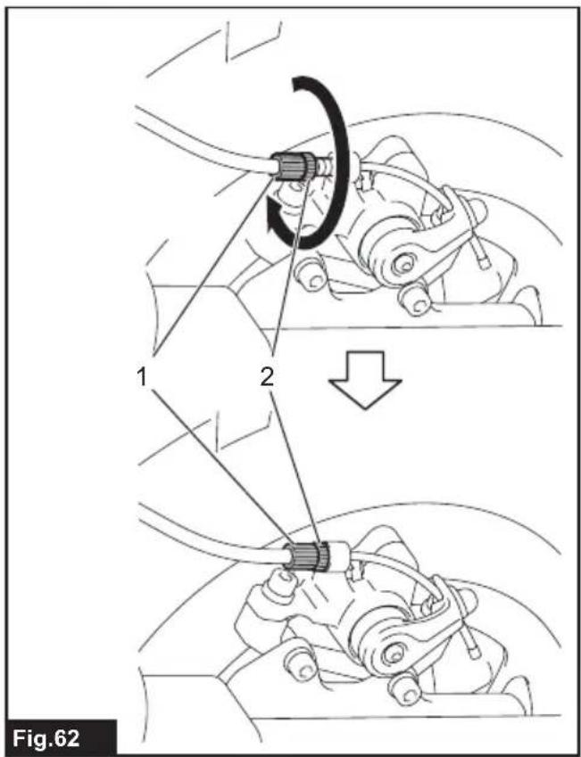
text_image
Fig.62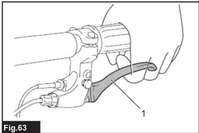
natural_image
Technical line drawing of a mechanical clamp or tool with labeled component (no text or symbols present)
text_image
Fig.64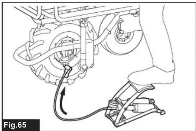
natural_image
Mechanical assembly diagram showing a car's wheel and suspension mechanism with no visible text or symbolsSPECIFICATIONS
| Model: DCU180 | ||
| Dimensions(L x W x H) | When carrier is installed During operation: 1,315 mm x 1,060 mm x 900 mmWhen stored: 1,110 mm x 820 mm x 820 mm | |
| When bucket is installed During operation: 1,310 mm x 820 mm x 900 mmWhen stored: 1,110 mm x 820 mm x 820 mm | ||
| Traveling speed Forward 1.5 or 3 | .5 km/h | |
| Reverse 1.0 km/h | ||
| Minimum turning radius 1,075 mm (Outer diameter when turning with front wheel as axis) | ||
| Maximum climbing capacity 12° | ||
| Maximum load capacity 130 kg | ||
| Brake Front wheel Disc brake with wire | ||
| Tire Front wheel Tubeless tire | ||
| Rated voltage | D.C. 18 V | |
| Net weight | When carrier is installed | 43.7 - 44.0 kg |
| When bucket is installed | 40.7 - 41.0 kg | |
• Due to our continuing program of research and development, the specifications herein are subject to change without notice.
• Specifications and battery cartridge may differ from country to country.
- The weight may differ depending on the attachment(s), including the battery cartridge. The lightest and heaviest combinations, according to EPTA-Procedure 01/2014, are shown in the table.
Applicable battery cartridge and charger
| Battery cartridge | BL1815N / BL1820B / BL1830B / BL1840B / BL1850B / BL1860B |
| Charger | DC18RC / DC18RD / DC18RE / DC18SD / DC18SE / DC18SF / DC18SH |
• Some of the battery cartridges and chargers listed above may not be available depending on your region of residence.
WARNING: Only use the battery cartridges and chargers listed above. Use of any other battery cartridges and chargers may cause injury and/or fire.
WARNING: Do not use a corded power supply such as battery adapter or portable power pack with this machine. The cable of such power supply may hinder the operation and result in personal injury.
Symbols
The followings show the symbols which may be used for the equipment. Be sure that you understand their meaning before use.


Ni-MH Li-ion
Only for EU countries Due to the presence of hazardous components in the equipment, waste electrical and electronic equipment, accumulators and batteries may have a negative impact on the environment and human health. Do not dispose of electrical and electronic appliances or batteries with household waste! In accordance with the European Directive on waste electrical and electronic equipment and on accumulators and batteries and waste accumulators and batteries, as well as their adaptation to national law, waste electrical equipment, batteries and accumulators should be stored separately and delivered to a separate collection point for municipal waste, operating in accordance with the regulations on environmental protection. This is indicated by the symbol of the crossed-out wheeled bin placed on the equipment.
 | Fully pull down the lever and check that the carrier or bucket is locked. |
 | Do not change the direction on steep slopes. |
 | Load and unload objects on flat ground. |
 | Load objects on the carrier or bucket evenly. |
 | This machine cannot be used on the public road. |
 | Do not use for transporting persons. |
| [XXZW] | Do not expose to rain. |
 | To cancel the beep sound, release the switch trigger and pull the brake lever. |
 | Do not stare into beam. |
 | Guaranteed sound power level according to EU Outdoor Noise Directive. |
 | Sound power level according to Australia NSW Noise Control Regulation |
Intended use
The machine is intended for loading and carrying objects with battery powered assistance.
Noise
The typical A-weighted noise level determined according to EN62841-1:
Sound pressure level ( L_pA ): 70 dB(A) or less Uncertainty (K): 3 dB(A)
The noise level under working may exceed 80 dB (A).
NOTE: The declared noise emission value(s) has been measured in accordance with a standard test method and may be used for comparing one tool with another.
NOTE: The declared noise emission value(s) may also be used in a preliminary assessment of exposure.
WARNING: Wear ear protection.
WARNING: The noise emission during actual use of the power tool can differ from the declared value(s) depending on the ways in which the tool is used especially what kind of workpiece is processed.
WARNING: Be sure to identify safety measures to protect the operator that are based on an estimation of exposure in the actual conditions of use (taking account of all parts of the operating cycle such as the times when the tool is switched off and when it is running idle in addition to the trigger time).
Vibration
The vibration total value (tri-axial vector sum) determined according to EN62841-1:
Work mode: operation without load
Vibration emission ( a_h ): 2.5 m/s ^2 or less Uncertainty (K): 1.5 m/s ^2
NOTE: The declared vibration total value(s) has been measured in accordance with a standard test method and may be used for comparing one tool with another.
NOTE: The declared vibration total value(s) may also be used in a preliminary assessment of exposure.
WARNING: The vibration emission during actual use of the power tool can differ from the declared value(s) depending on the ways in which the tool is used especially what kind of workpiece is processed.
WARNING: Be sure to identify safety measures to protect the operator that are based on an estimation of exposure in the actual conditions of use (taking account of all parts of the operating cycle such as the times when the tool is switched off and when it is running idle in addition to the trigger time).
EC Declaration of Conformity
For European countries only
The EC declaration of conformity is included as Annex A to this instruction manual.
SAFETY WARNINGS
General power tool safety warnings
WARNING: Read all safety warnings, instructions, illustrations and specifications provided with this power tool. Failure to follow all instructions listed below may result in electric shock, fire and/or serious injury.
Save all warnings and instructions for future reference.
The term "power tool" in the warnings refers to your mains-operated (corded) power tool or battery-operated (cordless) power tool.
Battery powered wheelbarrow safety warnings
- While operating the machine, always wear non-slip and protective footwear. Non-skid, closed-toed safety boots and shoes will reduce the risk of injury.
-
Inspect pathway before hauling objects/materials. Familiarizing yourself with the pathway and ensuring it is wide enough to safely navigate the machine under load will help reduce losing control of the machine.
-
Use extreme caution on slippery, loose and unstable terrain. Wet and slippery surfaces, such as wet grassy areas, snow or ice, and loose and unstable terrain, such as sand or gravel surfaces, may cause the machine to lose traction and may adversely affect steering, braking and stability.
-
Do not operate the machine on excessively steep slopes. This reduces the risk of loss of control, slipping and falling which may result in personal injury. Slopes greater than the maximum recommended grade and side grades may increase the risk of instability and may adversely affect the ability to stop safely.
-
When working on slopes, always be sure of your footing, always work across the face of slopes, never up or down, and exercise extreme caution when changing direction. This reduces the risk of loss of control, slipping and falling which may result in personal injury.
-
Whenever possible, use level areas for stopping, loading and unloading and never leave machine unattended on a slope. The machine is more unstable when resting on a slope than when resting on a level surface.
-
When stopping on slopes, face the machine uphill or downhill and block unbraked wheels. The machine is less stable when facing across a slope. Unbraked wheels, especially those of the castor-type, can potentially turn and roll downhill even while the front wheel parking brake is set.
-
When leaving the machine unattended, set parking brake once the machine is located in a safe stopping area. The parking brake prevents unwanted movement of the front wheel and can improve stability.
-
Ensure that ramps are clean, strong and secure. In order to reduce the risk of injury, all ramps must be clear of loose debris and strong enough to withstand the weight of anticipated loads that will be moved over them. They must have adequate blocking underneath and to both sides to eliminate deflections and side-to-side movement under load. All ramps must be wide enough to have sure footing while hauling loads across them.
-
Ensure the hopper is down and hoppers and dump-gates are securely latched when not dumping the load and when storing the machine. Unlatched hoppers or dump-gates can unexpectedly open or shift.
-
Avoid extending ramps without toe boards or railings over open spaces. Elevated open spaces and open trenches invite accidental falls and increase the potential for serious injury. Use toe boards or railings on ramps over open spaces to prevent driving the machine off the ramp.
-
Ensure all locking screws are tightly secure before using. Locking screws on the rear wheels and open-type carrier front and side walls must be secure to prevent unwanted movement of these adjustable parts of the machine.
-
Never operate the machine in an overloaded condition. Make sure the machine has the proper capacity rating for the objects or materials that have to be hauled. Excessive loads will make the machine more difficult to maneuver and stop, will increase stopping time and distance, and will increase the risk of instability.
-
Never operate your machine in an over stacked condition. Stacking material above the tray rim or over the sides of the tray can cause the machine to be uncontrollably out of balance and control.
- Use containers and tie-downs to secure loads. Loose and/or insecure loads are more likely to shift which can result in loss of stability and control.
- Always maintain a firm grip on handles. Loss of control can increase the risk of personal injury.
- Remove safety key when not in use. The safety key prevents unwanted, powered use of the machine, such as by children or other untrained or unauthorized persons. Without the key, electric power cannot be turned “on”.
- This machine cannot be used on public roads. Use of the wheelbarrow on a public road is unlawful and could result in local jurisdiction penalties in addition it could result in personal injury.
- Use a sturdy plate with anti-slip and detachment prevention function when loading and/or unloading this machine for transportation, or moving this machine between different levels. Make sure the plate inclination does not exceed 12^ , and operate the machine slowly and carefully. Unstable and quick operation may result in overturn and/or falling.
- Do not disassemble, repair, or modify this machine.
Operation
- When operating the machine, stand behind the machine and hold the handles firmly.
- Do not operate the machine while riding on the machine.
- Do not allow others to ride on the machine.
- When operating the machine in reverse and walking backward, watch behind you and be careful not to slip or trip.
- Do not use the machine when visibility is poor because there is a risk of striking obstacles.
- When operating the machine on rough ground, decrease speed and exercise caution.
- When using the machine, avoid soft ground to prevent overturn due to the shoulder of the road collapsing.
- Do not operate the machine on upward slopes greater than 12^ .
- If you find an abnormality, stop the machine on flat ground. Before inspecting the machine, pull the brake lever and lock the brake, and then turn the power off.
- Before operating the machine, make sure that the lock lever is fully pulled down and completely locked. If the lock is incomplete, there is a risk of accident or injury as the carrier or bucket may be tilted and the objects fall when going downhill.
- Be careful not to entangle the cords with the load or obstacles.
Operation on slopes
- Do not cross on slopes.
- Be sure to decrease speed and exercise caution.
- Exercise caution when starting or stopping the machine on slopes.
- As the loads become less stable on slopes, firmly secure the loads with ropes.
-
As the machine becomes unstable depending on the condition of the road, keep the load to a minimum.
-
As the view is obscured on slopes, keep the height of the load to a minimum.
- Never park the machine on steep slopes. Park the machine on flat ground, pull the brake lever and lock the brake, and then turn the power off.
- Do not change the direction or speed mode on steep slopes.
- Do not release the switch trigger on upward slopes. The machine may go in reverse and cause an accident.
- Make sure that the remaining battery capacity is enough before operating on slopes. If the remaining battery capacity is not enough, charge the battery or replace it with a charged one.
Loading objects
- Do not overload objects. When loading objects, be sure to follow the instructions and load limits in the manual.
- Firmly secure the objects with ropes.
- Load the objects within the carrier or bucket. If the objects protrude from the carrier or bucket, there is a risk of accidents due to the objects falling or contact obstacles such as walls.
- Be sure that loaded objects are below eye level. If the load is too high, it is dangerous because the view is obscured. Also, there is a risk of overturning and injury because the load is likely to be unbalanced.
- Load the objects on the carrier or bucket evenly. If the objects are loaded unevenly, there is a risk of overturning and injury because the load is likely to be unbalanced.
- Before loading the objects or operating the machine, make sure that the lock lever is fully pulled down and completely locked.
- Be sure to load heavy objects first to keep balance.
- Do not extend the front and side rails on steep slopes. Extend the side rails when lightweight objects are loaded.
- When extending the front and side rails, do not extend them over the extension limit. Be sure to extend the side rails so that the right and left sides are the same length, and load objects evenly.
- Load and unload objects on flat ground.
- When lifting and tilting the carrier or bucket, hold the handles and frame firmly, and work in a stable posture.
Maintenance
- Always be sure to park the machine on flat ground and lock the brake lever before storage or attempting to perform inspections or maintenance.
SAVE THESE INSTRUCTIONS.
⚠ WARNING: DO NOT let comfort or familiarity with product (gained from repeated use) replace strict adherence to safety rules for the subject product. MISUSE or failure to follow the safety rules stated in this instruction manual may cause serious personal injury.
Important safety instructions for battery cartridge
- Before using battery cartridge, read all instructions and cautionary markings on (1) battery charger, (2) battery, and (3) product using battery.
- Do not disassemble or tamper with the battery cartridge. It may result in a fire, excessive heat, or explosion.
- If operating time has become excessively shorter, stop operating immediately. It may result in a risk of overheating, possible burns and even an explosion.
- If electrolyte gets into your eyes, rinse them out with clear water and seek medical attention right away. It may result in loss of your eyesight.
- Do not short the battery cartridge:
(1) Do not touch the terminals with any conductive material.
(2) Avoid storing battery cartridge in a container with other metal objects such as nails, coins, etc.
(3) Do not expose battery cartridge to water or rain.
A battery short can cause a large current flow, overheating, possible burns and even a breakdown.
- Do not store and use the tool and battery cartridge in locations where the temperature may reach or exceed 50 °C (122 °F).
- Do not incinerate the battery cartridge even if it is severely damaged or is completely worn out. The battery cartridge can explode in a fire.
- Do not nail, cut, crush, throw, drop the battery cartridge, or hit against a hard object to the battery cartridge. Such conduct may result in a fire, excessive heat, or explosion.
- Do not use a damaged battery.
- The contained lithium-ion batteries are subject to the Dangerous Goods Legislation requirements.
For commercial transports e.g. by third parties, forwarding agents, special requirement on packaging and labeling must be observed.
For preparation of the item being shipped, consulting an expert for hazardous material is required.
Please also observe possibly more detailed national regulations.
Tape or mask off open contacts and pack up the battery in such a manner that it cannot move around in the packaging.
- When disposing the battery cartridge, remove it from the tool and dispose of it in a safe place. Follow your local regulations relating to disposal of battery.
- Use the batteries only with the products specified by Makita. Installing the batteries to non-compliant products may result in a fire, excessive heat, explosion, or leak of electrolyte.
-
If the tool is not used for a long period of time, the battery must be removed from the tool.
-
During and after use, the battery cartridge may take on heat which can cause burns or low temperature burns. Pay attention to the handling of hot battery cartridges.
- Do not touch the terminal of the tool immediately after use as it may get hot enough to cause burns.
- Do not allow chips, dust, or soil stuck into the terminals, holes, and grooves of the battery cartridge. It may result in poor performance or breakdown of the tool or battery cartridge.
- Unless the tool supports the use near high-voltage electrical power lines, do not use the battery cartridge near high-voltage electrical power lines. It may result in a malfunction or breakdown of the tool or battery cartridge.
- Keep the battery away from children.
SAVE THESE INSTRUCTIONS.
⚠️CAUTION: Only use genuine Makita batteries. Use of non-genuine Makita batteries, or batteries that have been altered, may result in the battery bursting causing fires, personal injury and damage. It will also void the Makita warranty for the Makita tool and charger.
Tips for maintaining maximum battery life
- Charge the battery cartridge before completely discharged. Always stop tool operation and charge the battery cartridge when you notice less tool power.
- Never recharge a fully charged battery cartridge. Overcharging shortens the battery service life.
- Charge the battery cartridge with room temperature at 10 °C - 40 °C (50 °F - 104 °F). Let a hot battery cartridge cool down before charging it.
- When not using the battery cartridge, remove it from the tool or the charger.
- Charge the battery cartridge if you do not use it for a long period (more than six months).
PARTS DESCRIPTION
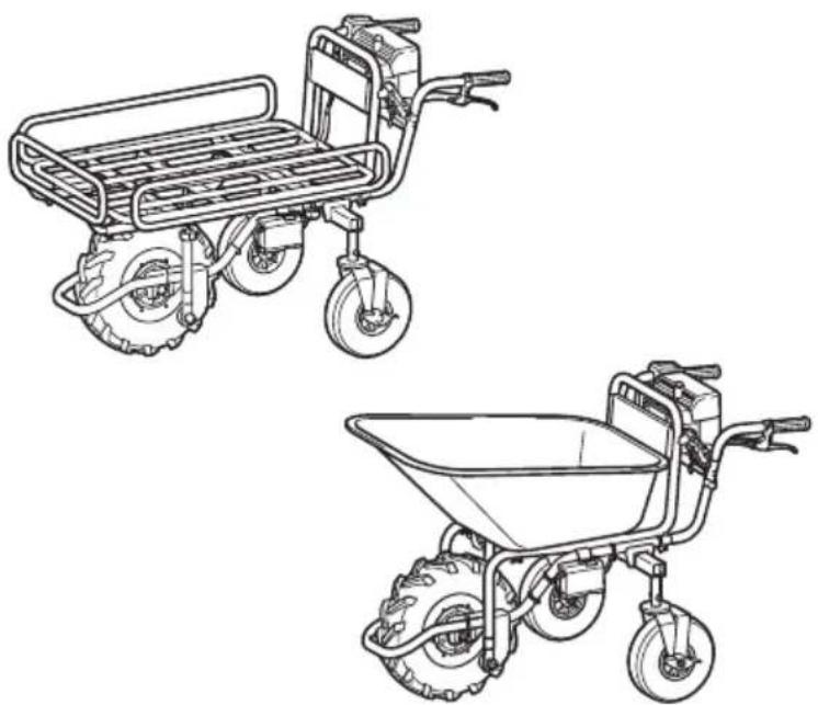
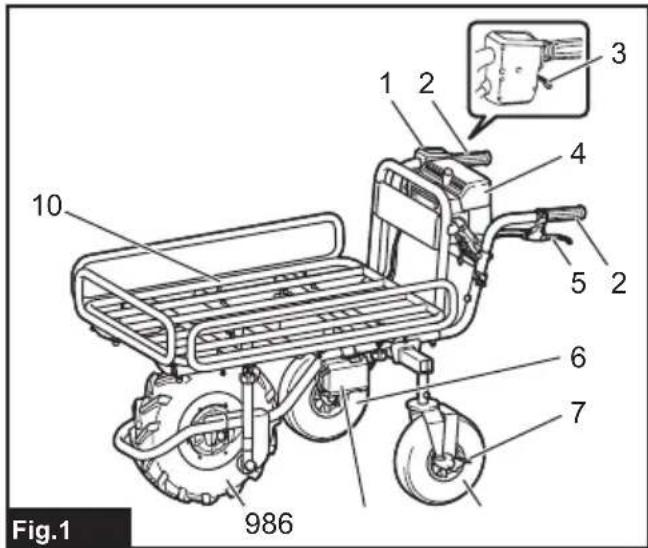
Parts description (when the carrier is installed)
▶ Fig.1
| 1 C | control panel 2 Handle | ||
| 3 S | witch trigger 4 Battery box | ||
| 5 B | rake lever for front wheel | 6 Rear wheel | |
| 7 B | rake pedal for rear wheel | 8 Lamp | |
| 9 F | ront wheel 10 Carrier | ||
Parts description (when the bucket is installed)
▶ Fig.2
| 1 Control panel 2 Handle | ||
| 3 Switch trigger 4 Battery box | ||
| 5 Brake lever for front wheel | 6 Rear wheel | |
| 7 Brake pedal for rear wheel | 8 Lamp | |
| 9 Front wheel 10 Bucket | ||
ASSEMBLY
CAUTION: Always be sure that the machine is switched off and the battery cartridge is removed before carrying out any work on the machine.
Assembling main unit
- Take out the base unit and handles from the box.
▶ Fig.3
NOTICE: Be sure to take out the base unit and handles together, so that excessive force is not applied to the cords.
- Place the packing material under the rear side of the base unit.
▶ Fig.4: 1. Packing material
3. Insert the rear wheels into the frame.
▶ Fig.5: 1. Rear wheel
▶ Fig.6: 1. Rear wheel
NOTE: The support legs can be attached instead of the rear wheels.
- Attach the spring washer and the washer to the short hexagonal bolt, and then tighten them using the wrench included in the package.
▶ Fig.7: 1. Short hexagonal bolt 2. Spring washer 3. Washer
▶ Fig.8
▶ Fig.8
NOTICE: Be sure to use the short hexagonal bolts to tighten the rear wheels.
NOTICE: Fix the rear wheels at the same position on both sides.
- Raise the handles, and then insert them into the base unit.
▶ Fig.9
NOTICE: Do not allow the cords inside area "A" in the figure. Long objects may be entangled with the cords and cause accidents.
NOTICE: Do not apply excessive force to the cords when raising and inserting the handles.
NOTICE: Be sure to raise the handles with both hands.
- Open the carrier frame toward the front.
▶ Fig.10: 1. Carrier frame
- Unfold the handles, then insert the long hexagonal bolts into the base unit, and then tighten the nuts with the wrench included in the package.
▶ Fig.11: 1. Long hexagonal bolt
- Tighten the shoulder bolts from the rear using the wrench included in the package.
▶ Fig.12: 1. Shoulder bolt
- Tighten the short hexagonal bolts from both sides using the wrench included in the package to fix the handles.
▶ Fig.13: 1. Short hexagonal bolt
NOTICE: Do not tighten the short hexagonal bolts with excessive force. Tighten them with proper force so that the handles are stably fixed.
NOTICE: Do not pinch the cords with the bolts.
- Fix the cords with the clamps.
▶ Fig.14: 1. Clamp
- Fold the carrier frame.
▶ Fig.15: 1. Carrier frame
- Press the lock button while pulling the brake lever to lock the brake.
▶ Fig.16: 1. Lock button 2. Brake lever
⚠️CAUTION: If the rear wheels are installed, press the brake pedal for the rear wheel to lock the rear wheel.
- Hook the carrier lock, and then pull down the lock lever to lock the carrier.
▶ Fig.17: 1. Carrier lock 2. Lock lever
NOTICE: Make sure that the lock lever is locked securely.
NOTICE: Do not pinch the cords with the lock lever.
NOTE: If you attach the support legs instead of the rear wheels, remove the rear wheels from the frames, and then attach the support legs to the frames.
▶ Fig.18: 1. Rear wheel 2. Support leg
Assembling and installing carrier
Optional accessory
- Take out the carrier from the box, attach the side rails to the base frame, and then tighten the thumb nuts to fix the rails.
▶ Fig.19: 1. Thumb nut
- Place the carrier on the base unit, and then insert the hexagonal bolts and washers into the frames from the top. Tighten the washers and spring washers and butterfly nuts from the bottom to fix the carrier.
▶ Fig.20: 1. Long hexagonal bolt 2. Short hexagonal bolt 3. Washer 4. Spring washer 5. Butterfly nut
NOTICE: Use the long bolts for the front, and the short bolts for the rear.
Installing bucket
Optional accessory
Place the bucket on the base unit, insert the hexagonal bolts into the frames, and then tighten the washers and spring washers and butterfly nuts from the bottom to fix the bucket.
▶ Fig.21: 1. Hexagonal bolt 2. Washer 3. Spring washer 4. Butterfly nut
FUNCTIONAL DESCRIPTION
Installing or removing battery cartridge
⚠️ CAUTION: Always switch off the machine before installing or removing of the battery cartridge.
CAUTION: Make sure that you lock the battery cover before use. Otherwise, mud, dirt, or water may cause damage to the product or the battery cartridge.
CAUTION: Always install the battery cartridge fully until the red indicator cannot be seen. If not, it may accidentally fall out of the machine, causing injury to you or someone around you.
⚠️ CAUTION: Do not install the battery cartridge forcibly. If the cartridge does not slide in easily, it is not being inserted correctly.
CAUTION: Do not use the high-temperature battery cartridge. When the high-temperature battery cartridge is used, the machine stops automatically before a short beep sound is emitted, and may cause an injury.
Installing the battery cartridge
- Rotate the lock lever, and then open the cover of the battery box.
▶ Fig.22: 1. Lock lever 2. Cover
- Align the tongue on the battery cartridge with the slot on the battery box, and then slide the cartridge until it locks in place with a little click. If you can see the red indicator on the upper side of the button, battery cartridge is not locked completely.
▶ Fig.23: 1. Battery cartridge
- Insert the lock key in the place shown in the figure as far as it will go.
▶ Fig.24: 1. Lock key
NOTE: If the lock key is not inserted completely, the machine does not work.
- Close the cover of the battery box, and then rotate the lock lever.
▶ Fig.25: 1. Lock lever 2. Cover
Removing the battery cartridge
- Rotate the lock lever, and then open the cover of the battery box.
- Pull out the battery cartridge from the battery box while sliding the button on the front of the cartridge.
▶ Fig.26: 1. Button
- Pull out the lock key.
- Close the cover of the battery box, and then rotate the lock lever.
Machine / battery protection system
The machine is equipped with a machine/battery protection system. This system automatically cuts off power to the motor to extend machine and battery life. The machine will automatically stop during operation if the machine or battery cartridge is under one of the following conditions. A short beep sound is emitted before the machine stops automatically. The battery indicators and LED indicators blink while the beep sound is emitted.
Overload protection
When the machine is operated in a manner that causes it to draw an abnormally high current, the machine automatically stops without any indication. In this situation, turn the machine off and remove the cause of overload, and then turn the machine on to restart.
Overheat protection
When the machine is overheated, the machine stops automatically. Let the machine cool down before turning the machine on again. The overheat protection is likely to work under high temperature environment.
Overdischarge protection
When the battery capacity becomes low, the machine stops automatically. If the machine does not operate even when the switches are operated, remove the battery cartridge and charge it.
Switching the battery cartridge
▶ Fig.27: 1. Battery selection switch
Up to two battery cartridges can be installed in the battery box, although the machine uses one battery cartridge for operation. Before operating the machine, select the battery cartridge used for operation by pressing the number on the battery selection switch.
NOTICE: If only one battery cartridge is installed in the battery box, be sure to select the battery box in which the battery cartridge is installed.
Indicating the remaining battery capacity on the battery box
⚠️CAUTION: Before checking the remaining battery capacities or switching the battery cartridge, be sure to stop the machine.
▶ Fig.28: 1. Battery indicator 2. Check button
Press the check button to indicate the remaining battery capacities. The battery indicators correspond to each battery.
| Battery indicator status | Remaining battery capacity | |
| On | Off | |
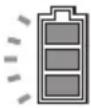 | 50% - 100% | |
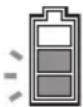 | 20% - 50% | |
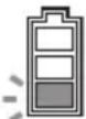 | 0% - 20% | |
 | Battery not installed | |
CAUTION: When the battery capacity becomes low, a short beep sound is emitted. If you continue to operate the machine at low battery capacity, a long beep sound is emitted and the machine automatically stops. When you hear the short beep sound, pull the brake lever and lock the brake, and then switch the battery cartridge to a charged one or charge the battery cartridge. When the remaining battery capacity runs out, the machine suddenly stops automatically and this may cause an injury.
NOTE: If you continue to pull the switch trigger even if you hear the short beep sound, the machine stops automatically. After the machine stops automatically, the beep sound continues and the support brake (electric brake) is enabled. To cancel the beep sound and release the support brake, pull the brake lever and release the switch trigger. Do not push the machine forcibly without releasing the support brake. After releasing the support brake, you can tell which battery protection system is working by checking the battery indicator status.
▶ Fig.29: 1. Lighting 2. Blinking 3. Turned off 4. Overheat protection 5. Overdischarge protection 6. Overload protection
CAUTION: If the beep sound is emitted while operating on slopes or the machine stops automatically on slopes, move the machine to a safe place, lock the brake, and then switch the battery cartridge to a charged one or charge the battery cartridge.
If the load is large, and the beep sound is emitted while operating on slopes or the machine stops automatically on slopes, do not move the machine forcibly. Lock the brake, pay attention to safety and switch the battery cartridge to a charged one, and then move the machine to a safe place. Reduce the load before operating the machine again.
NOTE: You can check the remaining battery capacity even if the lock key is not inserted.
Indicating the remaining battery capacity
Only for battery cartridges with the indicator
▶ Fig.30: 1. Indicator lamps 2. Check button
Press the check button on the battery cartridge to indicate the remaining battery capacity. The indicator lamps light up for a few seconds.
| Indicator lamps Remaining | capacity | ||
| Lighted Off | Blinking | ||
| 75% to 100% | |||
| 50% to 75% | |||
| 25% to 50% | |||
| 0% to 25% | |||
| Charge the battery. | |||
| The battery may have malfunctioned. | |||
NOTE: Depending on the conditions of use and the ambient temperature, the indication may differ slightly from the actual capacity.
NOTE: The first (far left) indicator lamp will blink when the battery protection system works.
Control panel
▶ Fig.31: 1. Power button 2. Forward/reverse button 3. Speed button
To turn the power on, press the power button for a few seconds. Press the forward/reverse button to switch between the forward mode and reverse mode. Press the speed button to switch between low speed and high speed. When the power is turned on, the forward mode and low speed are set. To turn the power off, press the power button for a few seconds.
NOTE: The forward/reverse button is not available while pulling the switch trigger.
NOTE: A short beep sound comes out when operating the machine in reverse.
NOTE: The speed button is not available when operating the machine in reverse.
Switch and brake action
WARNING: Before installing the battery cartridge into the machine, always check to see that the switch trigger actuates properly and returns to the "OFF" position when released.
To start the machine, pull the switch trigger. To stop the machine, release the switch trigger and pull the brake lever. To lock the brake lever, press the lock button while pulling the brake lever. To release the lock, pull the brake lever.
▶ Fig.32: 1. Switch trigger
▶ Fig.33: 1. Lock button 2. Brake lever
Rear wheel brake
The rear wheels are equipped with the brakes. Press the brake pedals toward the front to lock the brakes. To release the brakes, press the brake pedals toward the rear.
▶ Fig.34: 1. Pedal
Lighting up the front lamps
Press the lamp button on the battery box to light up the lamps. To turn off the lamps, press the lamp button again.
▶ Fig.35: 1. Lamp button 2. Lamp
NOTE: The lamps go off if the machine is left unattended for approximately 10 minutes.
NOTE: The lamps go off when the power is turned off.
NOTE: You can light up the lamps even if the lock key is not inserted.
Adjusting the handle height
Remove the short hexagonal bolts and shoulder bolts using the wrench included in the package, and then adjust the handle height. The height can be adjusted to three levels. Tighten the shoulder bolts and short hexagonal bolts to fix the handle.
▶ Fig.36: 1. Short hexagonal bolt 2. Shoulder bolt
NOTICE: Fix the left and right handles at the same height.
NOTICE: Do not tighten the short hexagonal bolts with excessive force. Tighten them with proper force so that the handles are stably fixed.
NOTICE: Do not pinch the cords with the bolts.
Adjusting the width of the carrier
Loosen the 4 thumb nuts, and then slide the side rails. Tighten the thumb nuts to fix the side rails.
▶ Fig.37: 1. Thumb nut 2. Rail
⚠️ CAUTION: Do not slide the rails beyond the limit mark.
▶ Fig.38
OPERATION
Operating the machine
NOTICE: The front wheel is driven by battery power in this machine. Use this machine to assist with carrying operations.
NOTICE: Be sure to insert the lock key in the battery box before the operation. If the lock key is not inserted, a short beep sound is emitted when you pull the switch trigger. The beep sound stops by releasing the switch trigger and pulling the brake lever.
Before operating the machine, check that the brake lever works properly.
▶ Fig.39: 1. Brake lever
WARNING: If the brake lever reaches the handle when you fully pull the lever, the brake is not working properly. Adjust the brake, or ask your local Makita Service Center for repairs.
-
Select the battery cartridge with the battery selection switch.
-
Press the power button on the control panel for a few seconds to turn the power on.
▶ Fig.40: 1. Power button
- Pull the brake lever to release the lock of the brake lever.
▶ Fig.41: 1. Lock button 2. Brake lever
NOTE: Release the rear wheel brake if the rear wheels are installed.
- Hold the handles firmly with both hands.
▶ Fig.42
- Pull the switch trigger.
▶ Fig.43: 1. Switch trigger
Loading objects
CAUTION: Before loading objects on the machine, make sure that the power is off and the brake lever is locked.
⚠️CAUTION: If the rear wheels are installed, make sure that the rear wheel brake is locked before loading objects on the machine.
⚠️CAUTION: Before loading objects on the machine, make sure that the carrier or bucket is locked.
⚠CAUTION: Be sure to load objects within the carrier or bucket. If objects are sticking out of the carrier or bucket, they may fall or collapse if they touch obstacles.
▶ Fig.44
⚠CAUTION: Be sure to load objects so that they are below eye level. If the load is too high, it is dangerous because the view is obscured. Also, there is a risk of overturning and injury because the load is likely to be unbalanced.
▶ Fig.45
When loading objects on the carrier, secure the objects with ropes and tie them down to the rope hooks.
▶ Fig.46
Dumping objects
CAUTION: Lift the carrier or bucket on flat and stable ground. Operation on unstable ground may cause an accident or injury.
You can dump the objects by lifting and tilting the carrier or bucket.
- Stop the machine, and then lock the brakes.
NOTICE: It is recommended to block the front wheel to stabilize the machine.
-
Release the lock lever.
-
Stand at the side of the machine, hold the handle with one hand, and then lift and tilt the carrier or bucket by pushing up the carrier frame with the other hand.
▶ Fig.47
CAUTION: Hold the handle and carrier frame firmly, and work in a stable posture.
CAUTION: Keep the load to a minimum. If the load is large, do not try to lift the carrier. Reduce the load, and then lift the carrier.
CAUTION: After dumping the objects, be sure to lock the carrier or bucket.
MAINTENANCE
CAUTION: Always be sure to park the machine on flat ground and lock the brake lever before storage or attempting to perform inspections or maintenance.
CAUTION: If the rear wheels are installed, make sure that the rear wheel brake is locked before storage, inspections, or maintenance.
CAUTION: Always be sure that the lock key and battery cartridge are removed from the machine before storage, inspections, or maintenance.
CAUTION: Always remove the lock key when the machine is not in use. Store the lock key in a safe place out of reach of children.
Periodic checks
- Check that the bolts and nuts are tightened firmly.
▶ Fig.48
- Check that the carrier is locked when the lock lever is fully pulled down.
▶ Fig.49: 1. Carrier lock 2. Lock lever
- Check that the brake lever works properly.
▶ Fig.50: 1. Brake lever
WARNING: If the brake lever reaches the handle when you fully pull the lever, the brake is not working properly. Adjust the brake, or ask your local Makita Service Center for repairs.
- Check to see if the front wheel is not damaged or flat. Check that the air in the tire for the front wheel is sufficient.
Cleaning the machine
NOTICE: Never use gasoline, benzine, thinner, alcohol or the like. Discoloration, deformation or cracks may result.
NOTICE: Pour the water below the carrier or bucket when cleaning the machine with running water. Do not use the high pressure washer for cleaning.
Remove mud, dirt, and the like from the machine. Clean the machine with running water. After the cleaning, wipe the machine with a dry cloth.
Storage
Remove the lock key. Store the machine in a safe place out of the reach of children.
When storing the machine, the handles can be turned toward the front. Remove the short hexagonal bolts and shoulder bolts using the wrench included in the package. Turn the handles toward the outside, and then rotate the handles to the front. Tighten the shoulder bolts and short hexagonal bolts to fix the handles.
▶ Fig.51: 1. Shoulder bolt 2. Short hexagonal bolt
NOTICE: Do not tighten the short hexagonal bolts with excessive force. Tighten them with proper force so that the handles are stably fixed.
NOTICE: Do not pinch the cords with the bolts.
Adjusting the brake
⚠️CAUTION: If the rear wheels are installed, be sure to lock the rear wheel brake before adjusting the brake.
- Remove the carrier or bucket, and then open the carrier frame.
▶ Fig.52: 1. Carrier frame
- Pull the brake lever to release the lock button of the brake lever.
▶ Fig.53: 1. Lock button 2. Brake lever
- Loosen the adjusting sleeve and fixing nut.
▶ Fig.54: 1. Adjusting sleeve 2. Fixing nut
- Tighten the fixing nut only.
▶ Fig.55: 1. Fixing nut
- Loosen the adjusting sleeve and fixing nut.
▶ Fig.56: 1. Adjusting sleeve 2. Fixing nut
- Tighten the fixing nut only.
▶ Fig.57: 1. Fixing nut
- Make sure that the brake lever is in the halfway position when it is fully pulled. If the brake lever is in the halfway position, go to step 13. If the brake lever is not in the halfway position, go to step 8.
▶ Fig.58: 1. Brake lever
- Loosen the fixing nut only.
▶ Fig.59: 1. Fixing nut
- Tighten the fixing nut and adjusting sleeve together.
▶ Fig.60: 1. Adjusting sleeve 2. Fixing nut
- Loosen the fixing nut only.
▶ Fig.61: 1. Fixing nut
- Tighten the fixing nut and adjusting sleeve together.
▶ Fig.62: 1. Adjusting sleeve 2. Fixing nut
- Make sure that the brake lever is in the halfway position when it is fully pulled.
▶ Fig.63: 1. Brake lever
- Fold the carrier frame, and then attach the carrier or bucket.
▶ Fig.64: 1. Carrier frame
Refilling the tire with air
Check that the air in the tire for the front wheel is not missing. If the air in the tire is insufficient, refill the tire with air using an inflator. The recommended tire pressure is 230 KPa.
▶ Fig.65
OPTIONAL ACCESSORIES
CAUTION: These accessories or attachments are recommended for use with your Makita tool specified in this manual. The use of any other accessories or attachments might present a risk of injury to persons. Only use accessory or attachment for its stated purpose.
CAUTION: Only use the Makita accessory or attachment for the machine. Use of any other accessory or attachment may result in serious personal injury.
If you need any assistance for more details regarding these accessories, ask your local Makita Service Center.
- Carrier
- Bucket
- Auxiliary wheels
- Makita genuine battery and charger
NOTE: Some items in the list may be included in the tool package as standard accessories. They may differ from country to country.
SPÉCIFICATIONS
▶ Abb.24: 1. Sperrschlüssel
⚠ WAARSCHUWING: Draag gehoorbescherming.
VEILIGHEIDSWAAR- SCHUWINGEN
▶ Fig.29: 1. Brandt 2. Knippert 3. Uit
- Oververhittingsbeveiliging
- Overontladingsbeveiliging
- Overbelastingsbeveiliging
OPTIONELE ACCESSOIRES
▶ Fig.11: 1. Perno hexagonal largo
- Segure as pegas firmemente com ambas as mãos.
▶ Fig.42
▶ Fig.10: 1. Transportramme
▶ Fig.15: 1. Transportramme
▶ Fig.52: 1. Transportramme
▶ Fig.64: 1. Transportramme