Solidcom C1 Pro - Microphone Hollyland - Free user manual and instructions
Find the device manual for free Solidcom C1 Pro Hollyland in PDF.

| Product Type | Wireless microphone (headset system) |
| Brand | Hollyland |
| Model | Solidcom C1 Pro |
| Dimensions (L x W x H) | 259.9 mm x 180.5 mm x 65.5 mm |
| Net weight | Approximately 1300 g (without antennas) |
| Power supply | DC, NP-F battery, V-mount battery, G-mount battery |
| Power consumption | < 4.5 W |
| Frequency band | 1.9 GHz (DECT) |
| Transmission range | 350 m (LOS) |
| Frequency response | 150 Hz - 7 kHz |
| Signal-to-noise ratio | > 55 dB |
| Harmonic distortion | < 1% |
| Max SPL input level | > 115 dB SPL |
| Number of headsets per hub | Up to 8 |
| Group modes | A, AB, Custom (via Web) |
| Key functions | Mute, Talk, Announce (general mute), A/B buttons |
| Hub connectivity | RJ45 (wired network), USB, Wi-Fi, 2-wire, 4-wire |
| Cascade connection | Via 4-wire (analog) or IP (digital), up to 300 m cable |
| Menu languages | Chinese, English |
| Operating temperature | 0 °C to 45 °C |
| Maintenance and cleaning | Avoid heat, water, non-original accessories |
| Safety | Do not place near heat sources, use original accessories |
| Spare parts and repairability | Contact Hollyland support |
Frequently Asked Questions - Solidcom C1 Pro Hollyland
User questions about Solidcom C1 Pro Hollyland
0 question about this device. Answer the ones you know or ask your own.
Ask a new question about this device
Download the instructions for your Microphone in PDF format for free! Find your manual Solidcom C1 Pro - Hollyland and take your electronic device back in hand. On this page are published all the documents necessary for the use of your device. Solidcom C1 Pro by Hollyland.
USER MANUAL Solidcom C1 Pro Hollyland
Hollyland Solidcom C1 Pro Hub
User Manual
V2.0
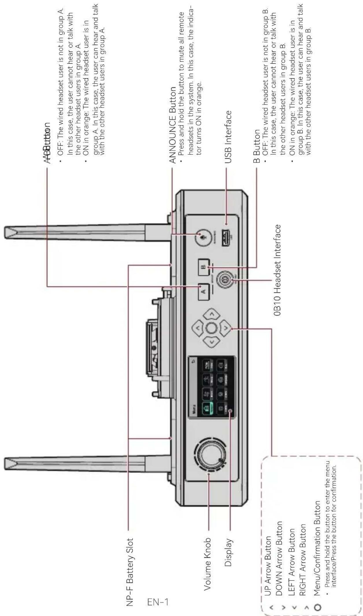
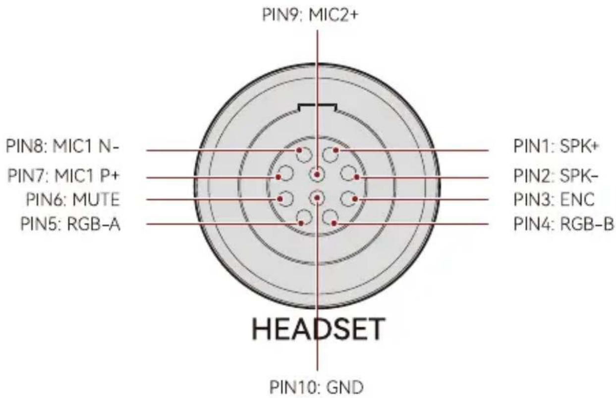
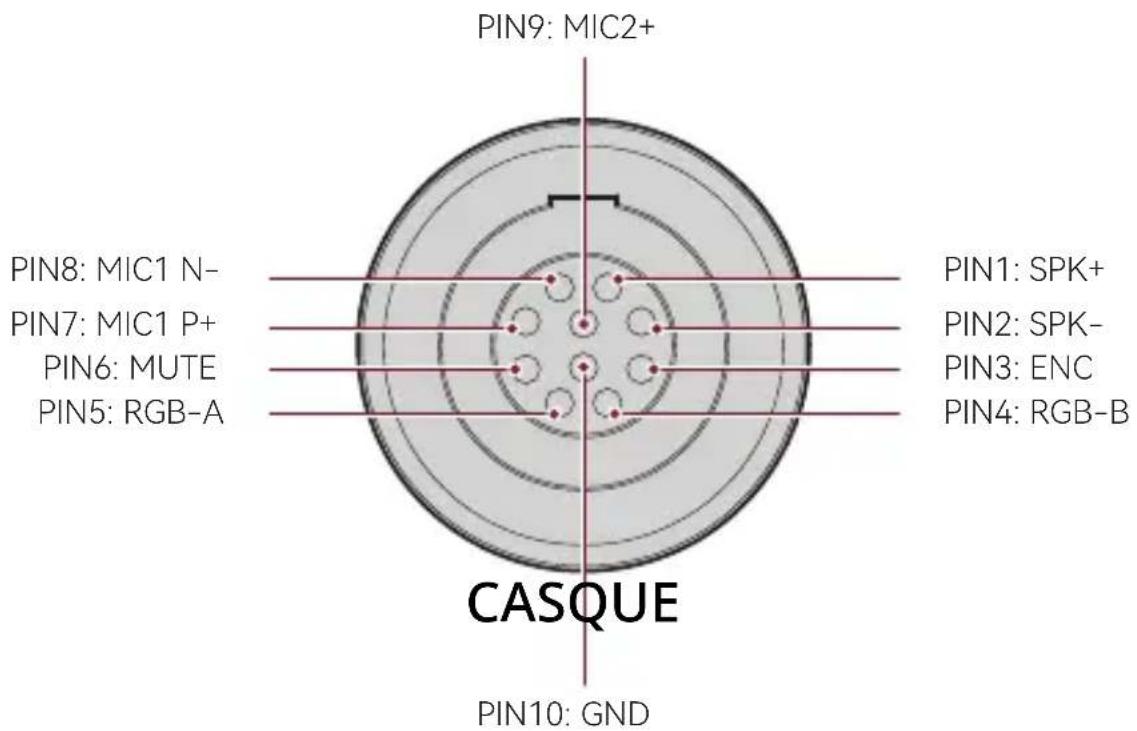
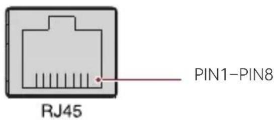
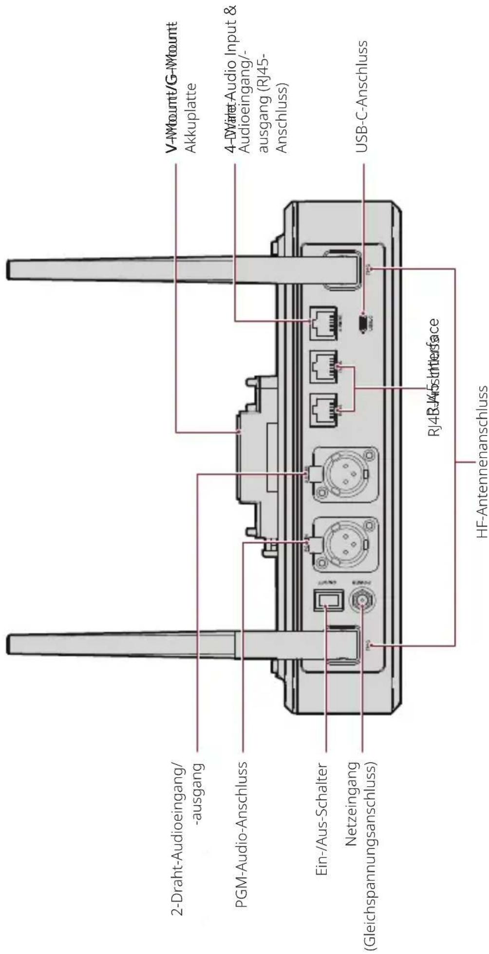
0B10 Wired Headset Interface
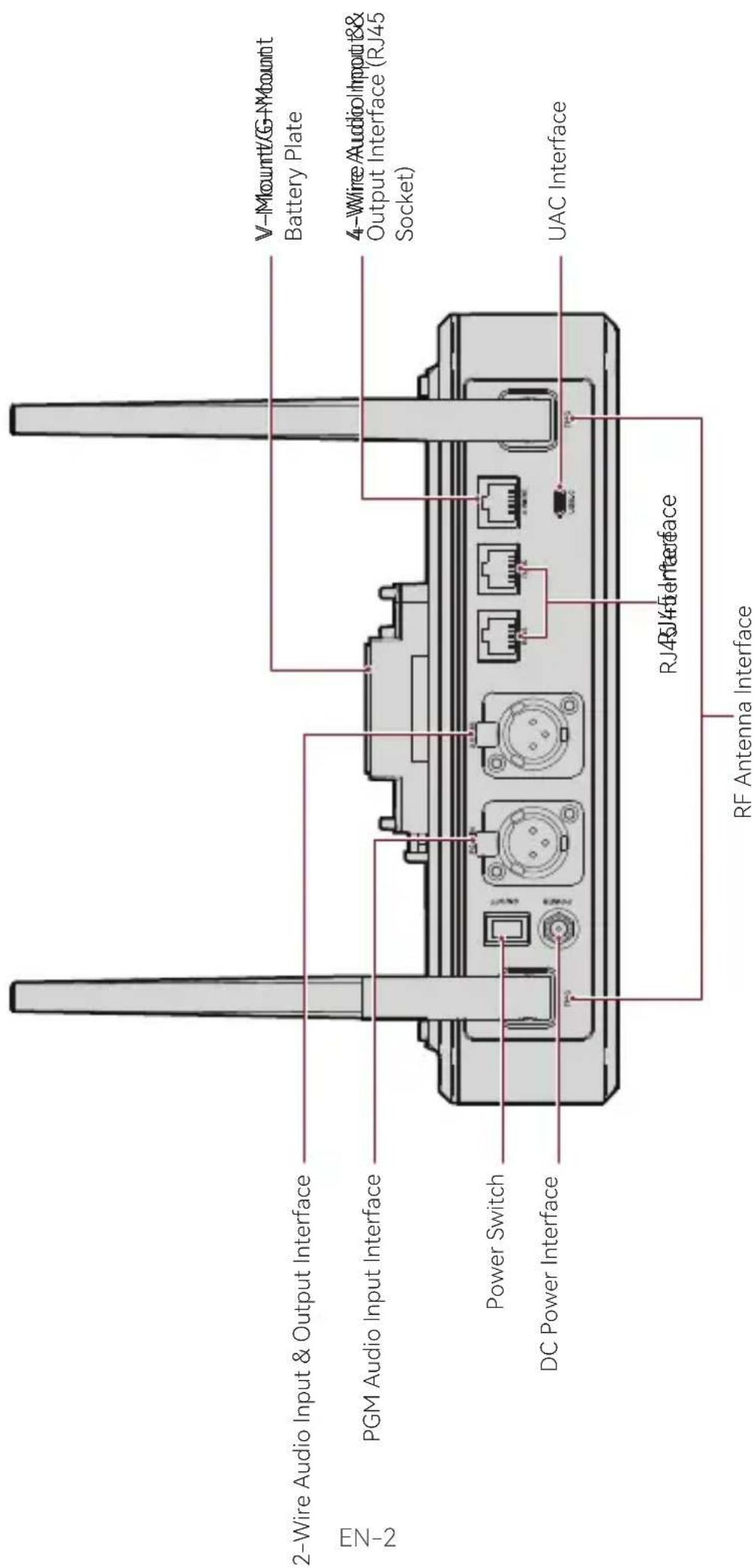
4-Wire Audio Input & Output Interface
4 WIRE
| Standard Line Sequence | |||
| PIN1 GND PIN5 AUDIO | OUT- | ||
| PIN2 GND PIN6 AUDIO | IN- | ||
| PIN3 AUDIO IN+ PIN7 | GND | ||
| PIN4 AUDIO OUT+ PIN8 | GND | ||
| Cross Line Sequence | |||
| PIN1 GND PIN5 AUDIO IN- | |||
| PIN2 GND PIN6 AUDIO OUT- | |||
| PIN3 AUDIO OUT+ PIN7 GND | |||
| PIN4 AUDIO IN+ PIN8 GND | |||
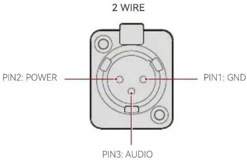
2-Wire Audio Input & Output Interface
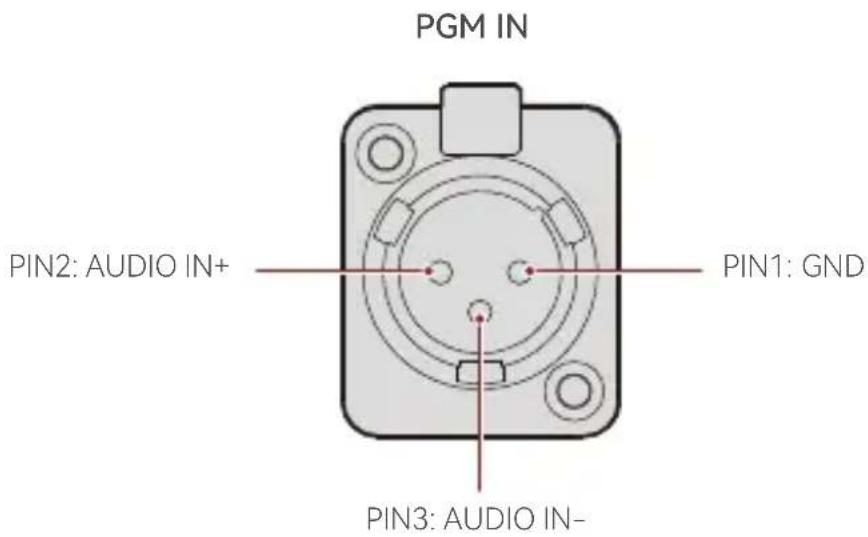
PGM Audio Input Interface
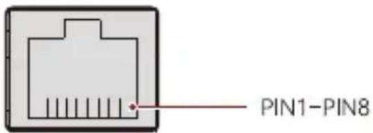
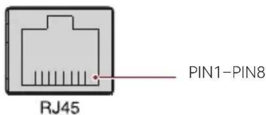
RJ451/RJ452 Interface
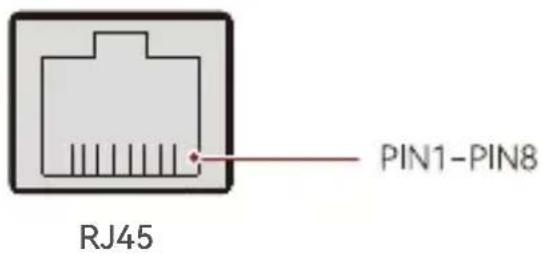
| Standard Line Sequence | |||
| PIN1 Transceive Data+ PIN5 Not connected | |||
| PIN2 Transceive Data- PIN6 Receive Data- | |||
| PIN3 Receive Data+ PIN7 Not connected | |||
| PIN4 Not connected PIN8 Not connected |
EN-4
Operation Guide
Hub Display Description
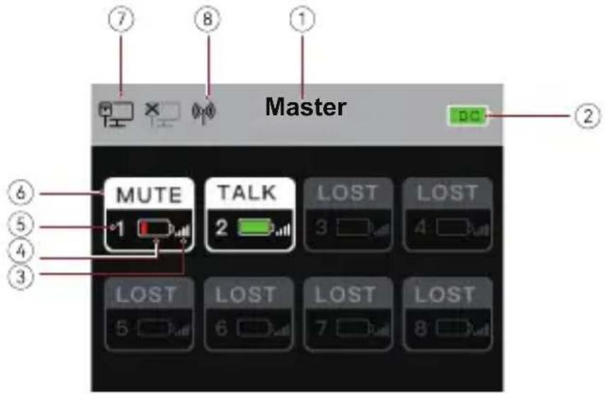
① Hub Mode (Master/Remote)
② Hub Battery Level
③ Headset Signal Strength
④ Headset Battery Level (Red: Low Battery)
⑤ Headset Number
⑥ Headset Status
TALK: The headset user can hear and talk with the other headset users.
MUTE: The headset user is muted and can only hear the other headset users.
LOST: The headset is disconnected from the hub.
LINK: The headset is reconnecting to the hub.
⑦ Network Connection Status
⑧ Wi-Fi Status
Operation Guide
Hub Menu Description
Press and hold the Menu/Confirmation button for about 3 seconds to enter the menu interface.
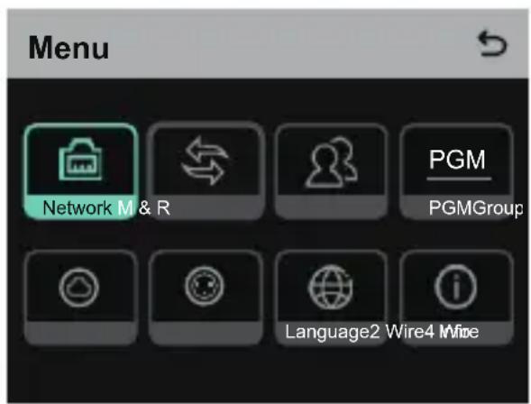
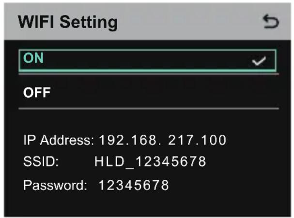
- Select Network to enter the network configuration interface.
1.1 Select Wifi Setting to turn Wi-Fi ON or OFF. After it is turned ON, the IP address, SSID, and password are displayed.
Operation Guide
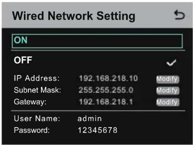
1.2 Select Wired Network Setting to turn DHCP ON or OFF. If it is turned OFF, you can also modify the IP address, subnet mask, and gateway as well as view the user name and password for logging in to the web.
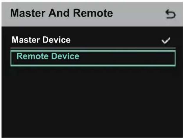
- Select M & R to set the hub as the master device or remote device.
2.1 SelectMaster Device to set the hub as the master device.
Operation Guide
2.2 Select Remote Device and then select Scan to scan the IP addresses of master devices on the network. Select the IP address of the corresponding master device in the displayed list and confirm it. Then, the hub is successfully set as the remote device.
- When a single hub is used, the hub needs to be set as the master device
- When more than two hubs are used in a cascaded connection, one hub needs to be set as the master device and the other hubs as the remote devices.
Master-Remote Device
Master 1 IP: 192.168.218.011
Master 2 IP: 192.168.218.012
Master 3 IP: 192.168.218.013
Master 4 IP: 192.168.218.014
Master 5 IP: 192.168.218.015
- Select Group to perform group settings and view group status.
3.1 There are three options: A group (All devices are in group A), AB group (All devices are in groups A and B), and Customize (The group settings can be customized on the web. All devices are in group A by default).
Group Presets

A group
AB group
Customize

Operation Guide
3.2 Select Group Review to view group settings.

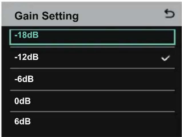
- Select PGM to set the PGM audio gain according to the input volume.
- Select 4 Wire to perform 4-wire audio settings.
5.1 Select Input Gain to set the input gain according to the input volume.

Operation Guide
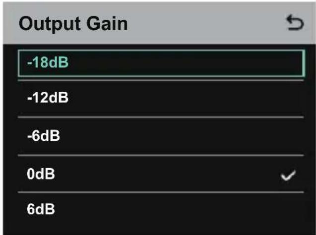
5.2 Select Output Gain to set the output gain according to the input volume.

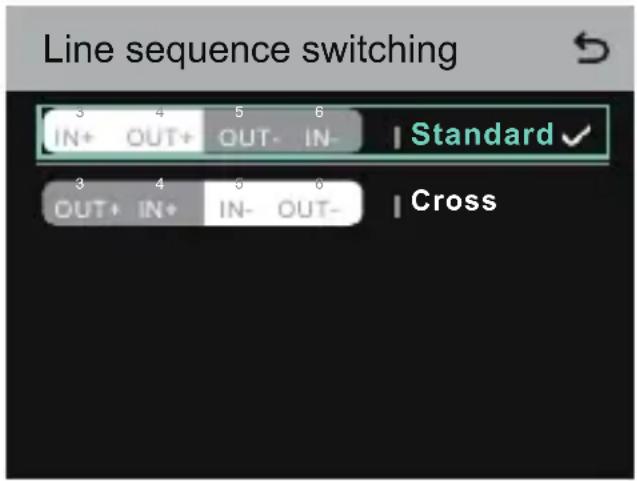
5.3 Select Line Sequence Switching to switch between Standard and Cross modes.
Operation Guide
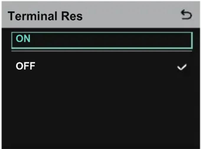
- Select 2 Wire to perform 2-wire audio settings.
6.1 Connect the hub to a 2-wire device and set the corresponding cable compensation and terminal resistance on the hub. Power on the 2-wire device and turn OFF or disconnect its microphone to make sure that there is no other audio transmission on the 2-wire link. Otherwise, the accuracy of auto-null settings may be affected. After Auto Null is selected, auto-null settings for the 2-wire device will be performed automatically on the hub.
6.2 Select Cable Compen to check the 2-wire cable length and select the corresponding compensation option according to the cable length.

6.3 Select Terminal Res to check whether the 2-wire device connected via the 2-wire interface has terminal resistance. If it has, select OFF. Otherwise, select ON.
Operation Guide
6.4 Select Input Gain to set the input gain according to the input volume.

6.5 Select Output Gain to set the output gain according to the input volume.
Operation Guide
- Select Language to perform language settings. You can switch between Chinese and English.

- Select Info to check related information about the hub.
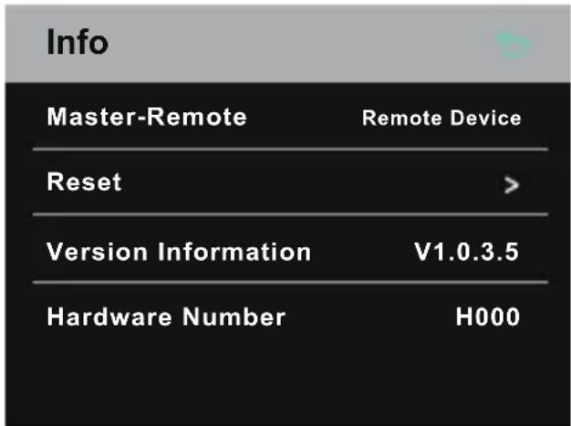
8.1 Select Reset to restore the configured hub information to the default settings.

Operation Guide
Performing Group Settings via a Computer
- Select Network > Wired Network Setting to view the default IP address, user name, and password of the hub.
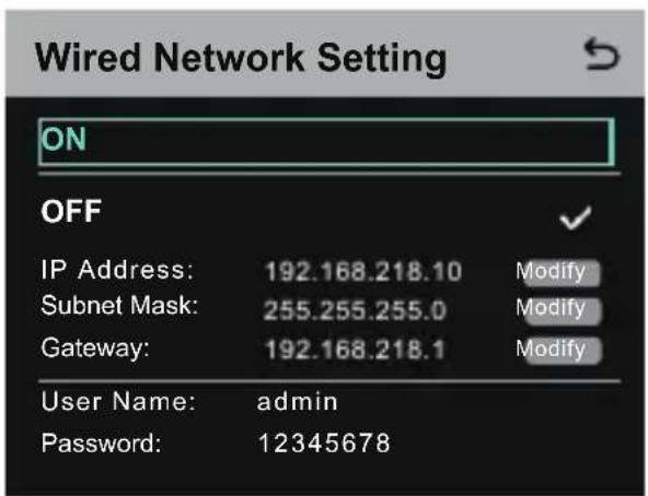
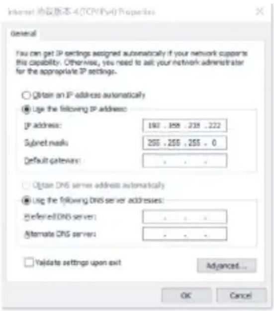
- Use a network cable to connect the hub to a computer via the RJ45 interface and set the IP address of the computer as 192.168.218.XXX. The default IP address of the hub is 192.168.218.10.
- Open a browser on the computer and visit http://192.168.218.10 to enter the configuration page for the hub.

Operation Guide
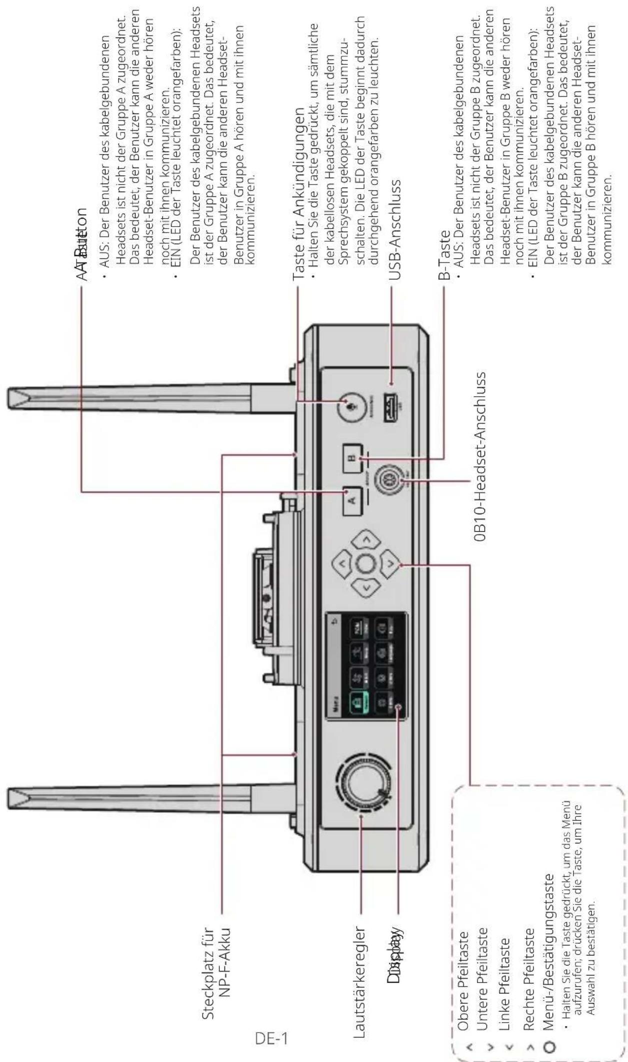
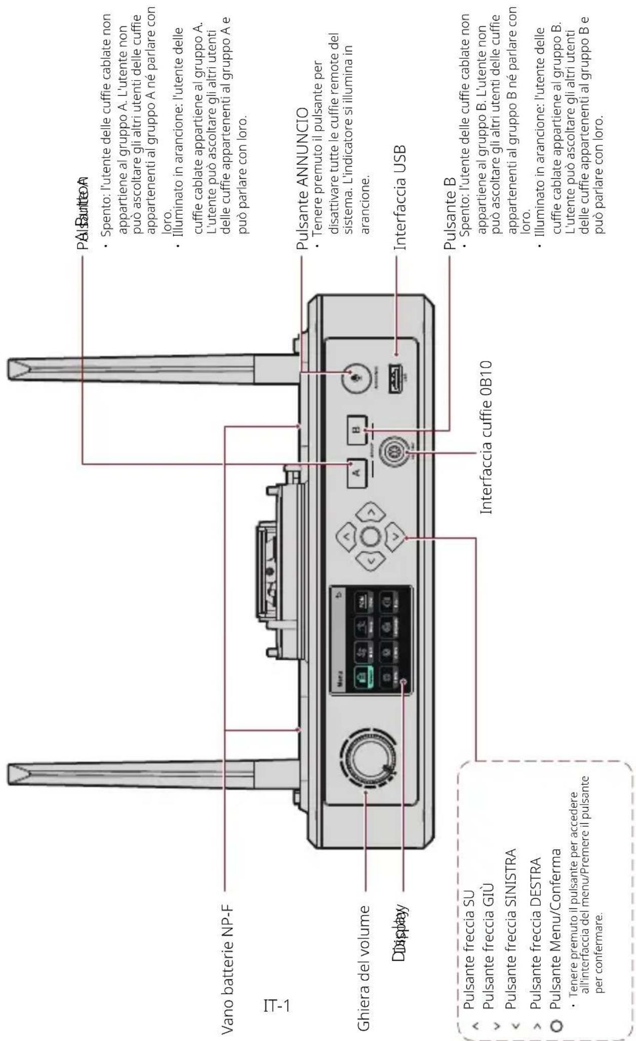
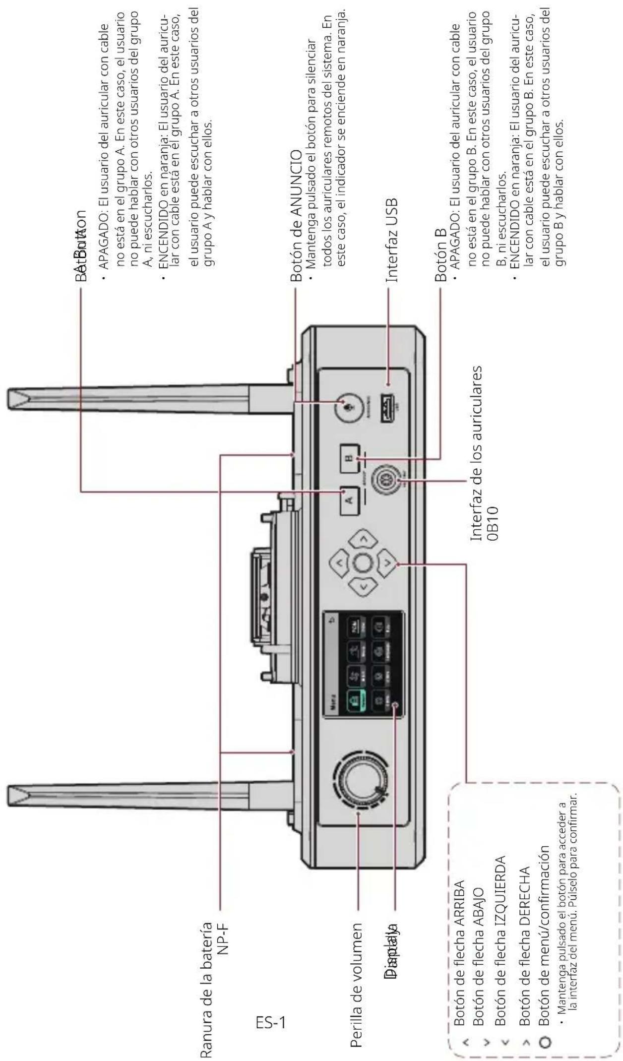
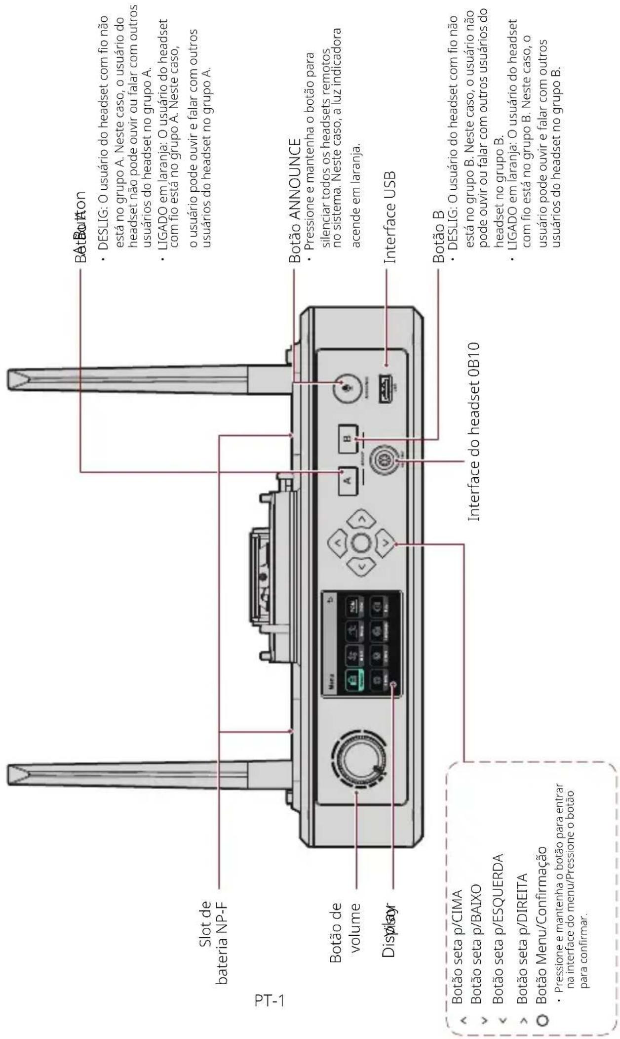
Group A & B Buttons on Headsets
After group settings are performed on the hub, the A or B button on a connected headset will light ON. The button light status indicates which group the headset has joined. To join or exit group A or B, simply press the A or B button on the headset.
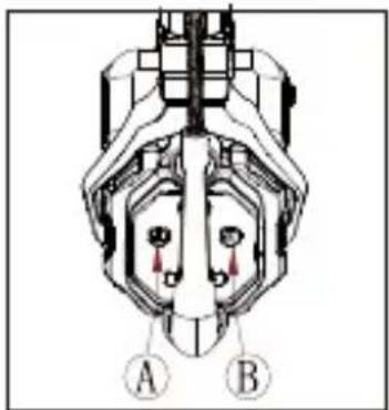
natural_image
Technical diagram of a mechanical component with labeled parts A and B (no text or symbols beyond labels)| A & B Button Light Status | Description |
| ON in orange | The headset user is in the corresponding group. In this case, the headset user can hear and talk with the other headset users in the group. |
| OFF | The headset user is not in the corresponding group. In this case, the headset user cannot hear or talk with the other headset users in the group. |
Operation Guide
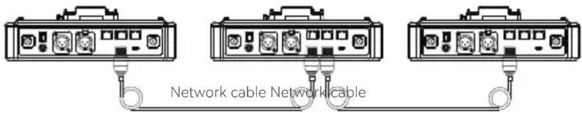
Cascaded Connection
Multiple hubs can be cascaded to expand the number of headsets. The hub supports two cascade methods — cascade via 4-wire analog signals and cascade via IP digital signals. Generally, it is recommended to cascade two hubs using 4-wire analog signals, and cascade three or more than three hubs using IP digital signals.
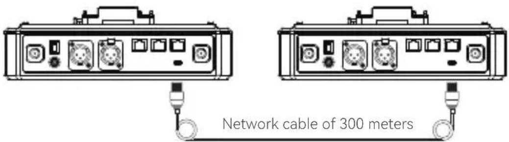
It is recommended to use a CAT5e cable for cascade and use the 568B standard for the RJ45 interface.
| Standard Network Cable Specifications Max Length | ||
 | CAT5eCAT6e | 300 meters |
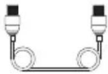
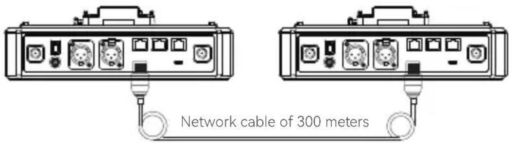
Two-System Cascaded Connection via the 4-Wire Interface
Use a standard network cable to connect two hubs via the 4-wire interface. The length of the network cable is up to 300 meters.
Operation Guide
4-Wire Settings
After connecting two hubs using a network cable, select 4 Wire > Line Sequence Switching on the hubs, and then select Standard on one hub and Cross on the other hub.
Hub Display
| Hub 1 | Select 4 Wire > Line Sequence Switching. | Select Standard. |
| 4-Wire Settings | 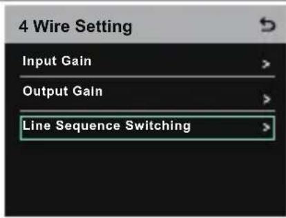 | 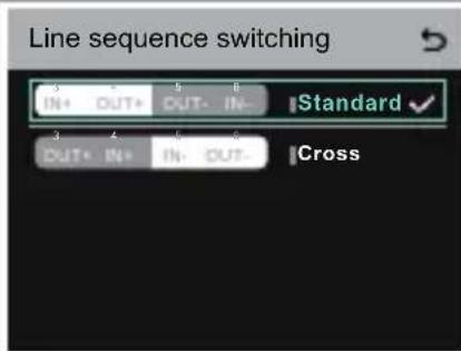 |
| Hub 2 | Select 4 Wire > Line Sequence Switching. | Select Cross. |
| 4-Wire Settings | 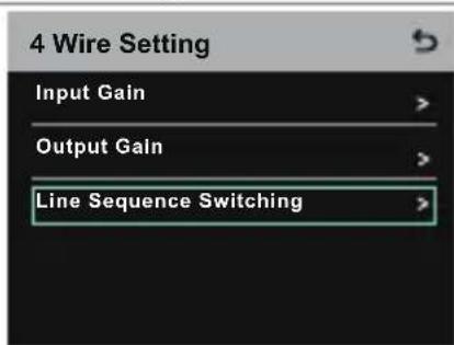 |  |
Two-System Cascaded Connection via the IP Network
Use a standard network cable to connect two hubs via the RJ45 interface. Either of the two RJ45 interfaces on the hub works. The length of the network cable is up to 300 meters.
Operation Guide
M & R Mode Settings
After connecting two hubs using a network cable, select M & R on the hubs to set the hub mode. On one hub, select Master Device. On the other hub, select Remote Device > Scan and then select the IP address of the corresponding master hub. Note that the function of obtaining the IP address automatically under Network> Wired Network Setting needs to be turned OFF on both two hubs.
Hub Display
| Hub 1 | Select Network > Wired Network Setting > OFF. | Select M & R > Master Device. |
| Network Settings | Wired Network SettingONOFFIP Address: 192.168.218.10ModifySubnet Mask: 255.255.255.0ModifyGateway: 192.168.218.1ModifyUser Name: adminPassword: 12345678 | 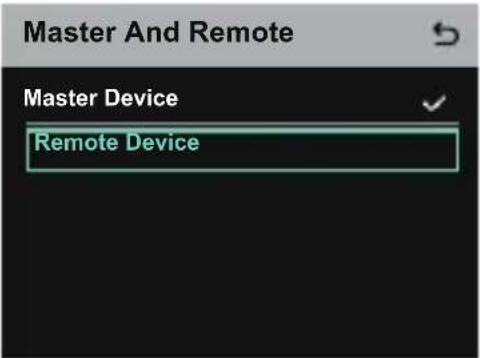 |
| Hub 2 | Select Network > Wired Network Setting > OFF. | Select M & R > Remote Device > Scan. |
| Network Settings | Wired Network SettingONOFFIP Address: 192.168.218.10ModifySubnet Mask: 255.255.255.0ModifyGateway: 192.168.218.1ModifyUser Name: adminPassword: 12345678 | 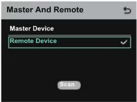 |
| AfterScanis selected, the IP addresses of master devices will be displayed. Then, select the desired IP address using the arrow buttons and press the Menu/Confirmation button to confirm the IP address. | 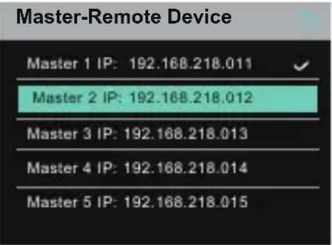 |
Operation Guide
Three-System Cascaded Connection via the IP Network
It is recommended to use the IP network connection to cascade three hubs. On one hub, select Master Device, and on the other two hubs, select Remote Device.
Parameters
| Antenna External | |
| Power Supply | DC power, NP-F battery, V-mount battery, G-mount battery |
| Volume Adjustment Adjustment knob | |
| Power Consumption < 4.5W | |
| Dimensions | (LxWxH): 259.9mm x 180.5mm x 65.5mm (10.2" x 7.1" x 2.6") |
| Net Weight About 1300g | (45.9oz) with the antennas excluded |
| Transmission Range 1,100ft (350m) LOS | |
| Frequency Band 1.9 GHz (DECT) | |
| Bandwidth 1.728MHz | |
| Wireless Technology Adaptive Frequency Hopping | |
| Wireless Power ≤ 21dBm | (125.9 mW) |
| Modulation Mode GFSK | |
| RX Sensitivity < -90dBm | |
| Frequency Response 150Hz-7kHz | |
| Signal-to-Noise Ratio > 55dB | |
| Distortion < 1% | |
| Input SPL | > 115dBSPL |
| Temperature Range | 0°C to 45°C (working condition) -10°C to 60°C (storage condition) |
Note:
1. The frequency band and wireless power vary by country and region.
2. The highest working temperature is 40^ C when the adapter is used for the power supply.
Safety Precautions
Do not place the product near or inside heating devices (including but not limited to microwave ovens, induction cookers, electric ovens, electric heaters, pressure cookers, water heaters, and gas stoves) to prevent the battery from overheating and exploding.
Do not use non-original charging cases, cables, and batteries with the product. The use of non-original accessories may cause electric shock, fire, explosion, or other dangers.
Support
If you encounter any problems in using the product or need any help, please contact Hollyland Support Team via the following ways:
Hollyland User Group
HollylandTech
HollylandTech
HollylandTech
support@hollyland.com
www.hollyland.com
Statement
All copyrights belong to Shenzhen Hollyland Technology Co., Ltd.
Trademark Statement
Without the written approval of Shenzhen Hollyland Technology Co., Ltd., no organization or individual may copy or reproduce part or all of any written or illustrative content and disseminate it in any form.
Note:
Due to product version upgrades or other reasons, this User Manual will be updated from time to time. Unless otherwise agreed, this document is provided as a guide for use only. All representations, information, and recommendations in this document do not constitute warranties of any kind, express, or implied.
HOLLYVIEW
Powered by Hollyland
Shenzhen Hollyland Technology Co., Ltd.
Hub Solidcom C1 Pro de Hollyland
Date of Vehicle Headset Position Board 10
Interface RJ451/RJ452
FR-8
Hollyland User Group
f HollylandTech
HollylandTech
HollylandTech
support@hollyland.com
www.hollyland.com
Déclaration
Powered by Hollyland
Shenzhen Hollyland Technology Co., Ltd.
Hollyland Solidcom C1 Pro Hub
Benutzerhandbuch
V2.0
4-DRAHT
Bedienungsanleitung
Master-Remote Device
Master 1 IP: 192.168.218.011
Master 2 IP: 192.168.218.012
Master 3 IP: 192.168.218.013
Master 4 IP: 192.168.218.014
Master 5 IP: 192.168.218.015
Bedienungsanleitung
Bedienungsanleitung
Bedienungsanleitung
Hollyland User Group
f HollylandTech
HollylandTech
HollylandTech
support@hollyland.com
www.hollyland.com
Powered by Hollyland
Shenzhen Hollyland Technology Co., Ltd.
Centralina Hollyland Solidcom C1 Pro
Manuale dell'utente
V2.0
Interfaccia RJ451/RJ452
Master-Remote Device
Master 1 IP: 192.168.218.011
Master 2 IP: 192.168.218.012
Master 3 IP: 192.168.218.013
Master 4 IP: 192.168.218.014
Master 5 IP: 192.168.218.015
Hollyland User Group
f HollylandTech
HollylandTech
HollylandTech
support@hollyland.com
www.hollyland.com
Dichiarazione
Powered by Hollyland
Shenzhen Hollyland Technology Co., Ltd.
Hub Solidcom C1 Pro de Hollyland
Manual de usuario
V2.0
ES-8
Hollyland User Group
f HollylandTech
HollylandTech
HollylandTech
support@hollyland.com
www.hollyland.com
Advertencia
Powered by Hollyland
Shenzhen Hollyland Technology Co., Ltd.
Hub Hollyland Solidcom C1 Pro
Manual do usuário
V2.0
Interface RJ451/RJ452

Guia de operação
Guia de operação
PT-8
Guia de operação
Guia de operação
Hollyland User Group
f HollylandTech
HollylandTech
HollylandTech
support@hollyland.com
www.hollyland.com
Declaração
Powered by Hollyland
Shenzhen Hollyland Technology Co., Ltd.