
Solidcom C1-4S - Intercom system Hollyland - Free user manual and instructions
Find the device manual for free Solidcom C1-4S Hollyland in PDF.


| Product Type | Wireless Intercom System |
| Brand | Hollyland |
| Model | Solidcom C1-4S |
| Dimensions (Headset) | Approx. 170 x 70 x 200 mm (each unit) |
| Weight (Headset) | Approx. 220 g (each unit) |
| Battery Type | Built-in rechargeable Li-ion battery |
| Battery Capacity | 1400 mAh per unit |
| Charging Interface | USB-C (5V/1A) |
| Operating Frequency | 2.4 GHz ISM band |
| Range | Up to 300 meters (line of sight) |
| Number of Users | Up to 4 (one master, three slaves) |
| Audio Mode | Full-duplex communication |
| Noise Cancellation | Advanced DSP noise reduction |
| Battery Life | Approx. 18 hours (continuous talk) |
| Charging Time | Approx. 2.5 hours |
| Material | ABS plastic with padded ear cushions |
| Maintenance | Wipe with dry cloth; keep away from moisture and extreme temperatures |
| Safety | Complies with FCC, CE, and RoHS standards |
| Spare Parts | Replacement battery, USB charging cable, ear cushions, foam windscreens |
| Warranty | 12 months from date of purchase (check local terms) |
Frequently Asked Questions - Solidcom C1-4S Hollyland
User questions about Solidcom C1-4S Hollyland
0 question about this device. Answer the ones you know or ask your own.
Ask a new question about this device
Download the instructions for your Intercom system in PDF format for free! Find your manual Solidcom C1-4S - Hollyland and take your electronic device back in hand. On this page are published all the documents necessary for the use of your device. Solidcom C1-4S by Hollyland.
USER MANUAL Solidcom C1-4S Hollyland
Thank you for purchasing Hollyland Full-duplex Wireless Intercom System.
The Solidcom C1 HUB8S includes eight single-sided remote wireless headsets along with eight rechargeable batteries, a charger, a HUB base with wired headset, and accessories. It is a full-duplex wireless DECT intercom system engineered to provide clear audio and all-day wearing comfort in a true-wireless design with no beltpack required. The system operates in the 1.9GHz band, providing a reliable transmission range up to 1000ft (350m) radius (LOS).
This Quick Guide will guide you through the installation and use of the equipment.
natural_image
Line drawing of a vintage electronic device with control panel and buttons (no text or symbols)①
natural_image
Illustration of a medical or laboratory device with tubing and connectors (no text or symbols visible)② ③
natural_image
Medical catheter device with tubing and connector (no visible text or labels)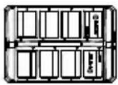
④
⑤
⑥
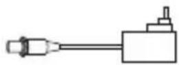
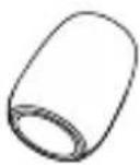
⑦
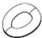
⑧
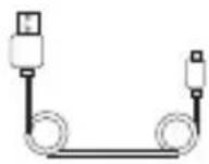
⑨
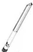
⑩
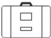
⑪
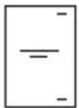
⑫
⑬
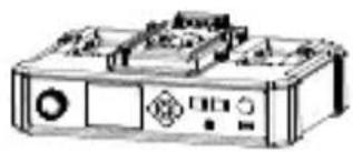
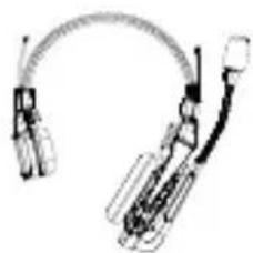
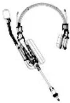
Solidcom C1 - HUB8S Headset Intercom Package
① HUB Base x1
② Remote Headset (with blue nameplate) x8
③ 3.5mm HUB Headset (with red nameplate) x1
④ Charging Case x1
⑤ Battery x16
⑥ Microphone Cushion x9
⑦ 12V/2A DC Adapter x2
⑧ Over-ear Cushion x9
⑨ USB Type-A to Type-C Cable x1
⑩ High-gain Antennas x4
⑪ Storage Case x1
⑫ Quick Guide x1
⑬ Warranty Card x1
Product Interfaces
A
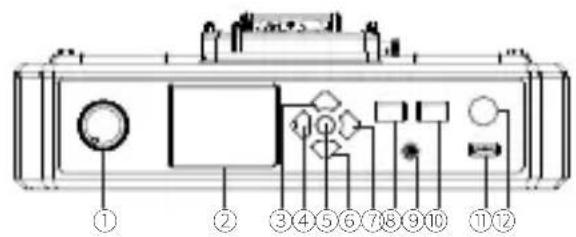
A HUB Base Interfaces
① HUB Headset Volume Knob
② Display
③ UP Arrow Key
④ LEFT Arrow Key
⑤ Menu/Confirm Button - Long press to enter the main menu/press once to confirm
⑥ DOWN Arrow Key
⑦ RIGHT Arrow Key
⑧ Join/Exit Group A Button for the 3.5mm HUB Headset - The indicator turns off when the HUB Headset exit Group A's conversation, and turns on in orange after joining in
⑨ 3.5mm Headphone Jack
⑩ Join/Exit Group B Button for the 3.5mm HUB Headset - The indicator turns off when the HUB Headset exit Group B's conversation, and turns on in orange after joining in
⑪ USB Interface
⑫ ANNOUNCE Button - Press and hold the button while making an ANNOUNCE, release the button when finished
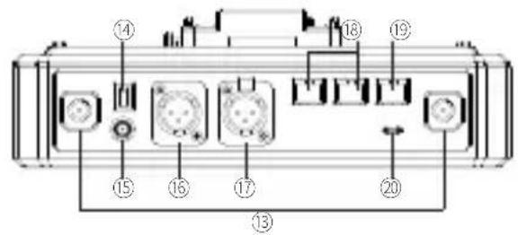
⑬ RF Antenna Interface
⑭ Power Switch
⑮ DC Power Interface
⑯ PGM Audio Input Interface
⑰ 2-wire Audio Input & Output Interface
⑱ RJ45 Network Port
⑲ 4-wire Audio Input & Output Interface (RJ45 network socket)
⑳ UAC Interface
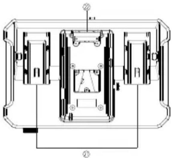
② NP-F Battery Bay
② V-Mount/G-Mount Battery Plate (Subject to the actual product you purchased)
B
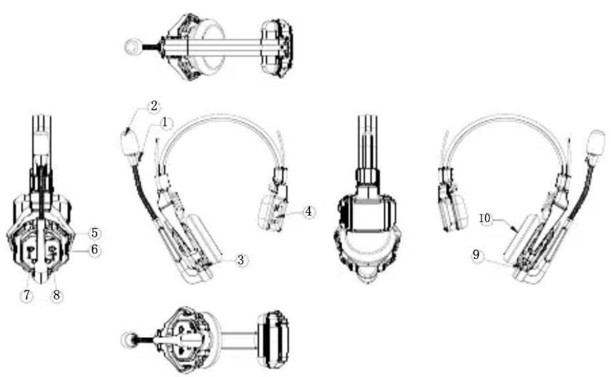
B Headset Interfaces
① Power/Connection Indicator
② Microphone
③ USB Type-C Interface - For firmware upgrade, and headset pairing
④ Battery Compartment
⑤ Volume + Button
⑥ Volume - Button
⑦ A Button - Lights up when joined Group A, turns off when exited Group A; Long press for 5 seconds to pair
⑧ B Button - Lights up when joined Group B, turns off when exited Group B
⑨ Power Button
⑩ Speaker
C

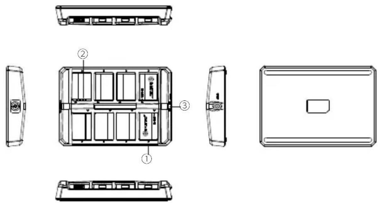
Charging Case Interfaces
① Charging Indicator
Orange: Charging in progress
Green: Fully charged
② Charging Contact
③ DC Charging Interface
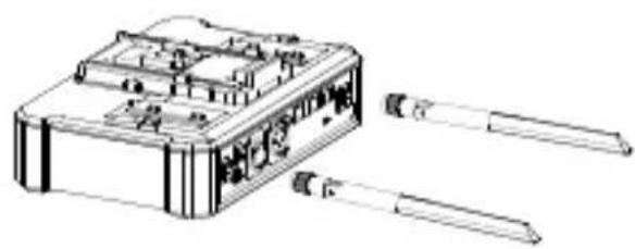
Set Up HUB Base
Install the HUB antennas.
natural_image
Technical line drawing of a mechanical device with internal components and two external tools (no text or symbols)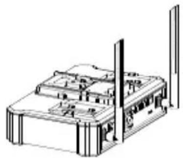
natural_image
Technical line drawing of a mechanical or electronic device with no visible text, numbers, or symbols.Power Up HUB Base
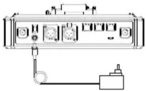
Connect the 12V/2A DC Adapter to the HUB base. Press the Power Switch to turn on.
natural_image
Diagram of a device rear panel with ports and connections, no text or symbols present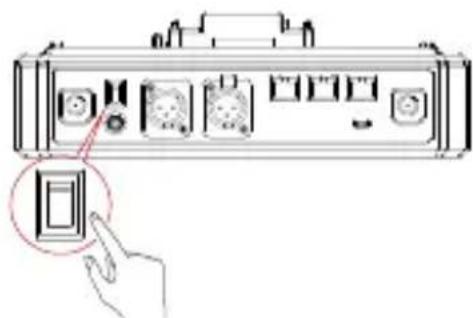
Note: The HUB Base can be powered using NP-F battery, V-Mount/G-Mount battery y, or DC power supply.
Quick Start Guide
Install Headset Battery
natural_image
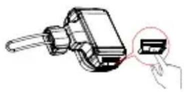
Illustration of a handheld device with a hand inserting a small electronic component (no text or symbols visible)Step 1: Slide the battery compartment cover lock
natural_image
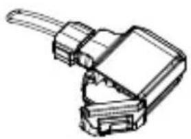
Technical line drawing of a mechanical clamp or connector (no text or symbols)Step 2: Open the cover Step 3: Place the battery into the compartment and close the battery cover
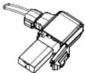
natural_image
Technical line drawing of a mechanical component with no visible text or symbolsTurn On Headset
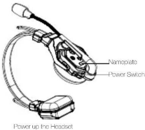
Note: The indicator light stops flashing and turns to static green when the HUB Base and the Remote Headset(s) are successfully connected.
Mute/Unmute Microphone
Mute/Unmute the headset's microphone by moving the mic boom up/down.
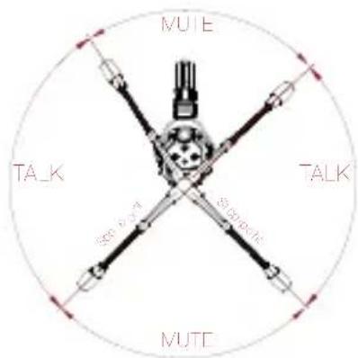
The device is now ready for use.
- Move the mic boom up to the MUTE position that makes a CLICK sound, and the HUB Base's interface displays "MUTE" corresponding to the headset status.
- Move the mic boom down to the TALK position that makes a CLICK sound, and the HUB Base's interface displays "TALK" corresponding to the headset status.
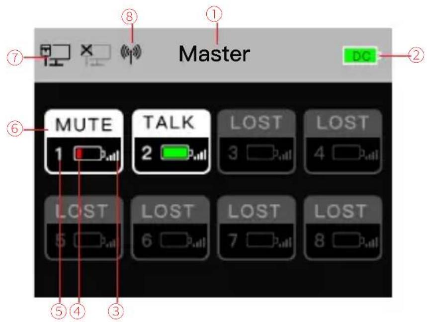
HUB Base Main Display Interfaces
① HUB Base configuration - Master/Slave
② HUB Base battery level
③ Headset signal strength
④ Headset battery level - turns red in low battery
⑤ Headset number
⑥ Headset status
TALK: Headset is active to hear and talk
MUTE: Headset is muted to hear only
LOST: Headset lost connection with HUB Base
⑦ Network connection status
⑧ WiFi status
Headset Status Indicator
natural_image
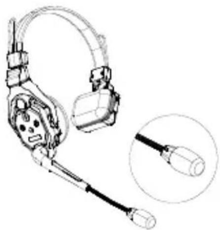
Technical line drawing of a headset with attached cable, shown with an inset close-up detail (no text or symbols)① FLASH GREEN: Headset disconnected
② STAT IC GREEN: Headset connection successful
③ FLASH RED: Low battery, please change the battery
Pairing Operation
The HUB Base and Remote Headsets that come in one system package will auto pair up right out of box. Manual pairing is only required when there is a need for adding or changing headset or HUB base to the system.
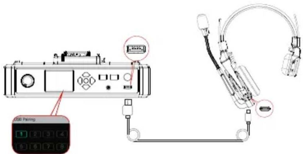
Connect the HUB Base and the Headset with a USB-C Cable.
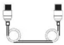
Pairing requires a USB-C cable.
Connect one end to the USB interface on the HUB Base's front panel, and the other end to the USB-C interface of the headset.
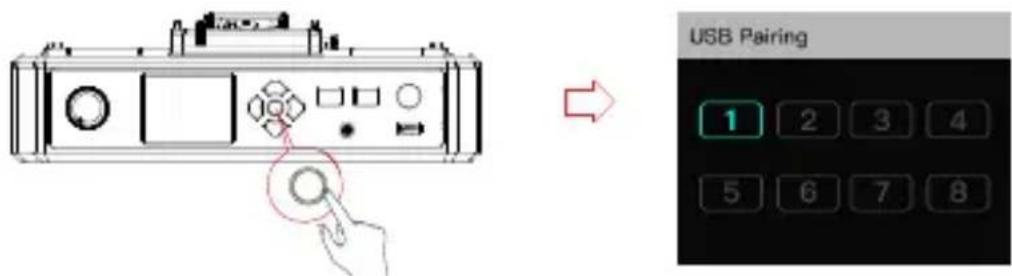
The HUB Base screen will display the Select Number interface. Locate the designed headset number with the arrow keys, and press the round Menu/Confirm Button to complete number setting and pairing.
Headset(s) Number Setting via HUB Base
When re-pairing and numbering the headset, be sure to turn on all the headsets to avoid selecting duplicate numbers, which may lead to connection failure with other headsets.
In case of wrong numbering of a headset, simply connect it to the HUB with the USB cable and operate the pairing and numbering process again.
Cascade Connections
Mu lt ip le s et s can be c as ca de d to e xp and d th e nu mb er o f he ad set s . Th e So li dc om C 1 Ba se s up port s tw o ca sc ad in g me th od s, 4 -w ir e an al og a nd I P di gi ta l si gn al c as ca 4- wi re a na lo g mo de i s ge ne ra ll y us ed i n ca sc ad in g co nn ec ti on s of 2 s et s, a nd t h di gi ta l si gn al c as ca de f or 3 s et s. I f mo re t ha n 3 set s a re c as ca de d, i t is r ec om
| Standard Network Cable | Cable Spec | Max. Length |
 | CAT 5oCAT 6o | 300m |
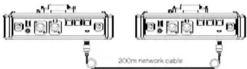
Two Systems Cascade via 4-Wire Interface
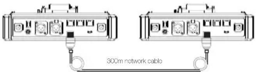
Use a standard network cable to connect two HUB bases through the 4W interface. The network cable is generally up to 300 meters long.
4 Wire Settings
After connecting the two systems with the network cable, configure each HUB Base's line sequence by entering "4 Wire Settings" and selecting "Line sequence switching". Set the first HUB Base to "Standard mode" and the second HUB Base to "Cross mode".
HUB Display Interfaces
| HUB 1 | Enter “4 Wi re” menu, and select “Line sequenc e switching ” | Set to “Standard mode” |
| 4 Wire Settings | 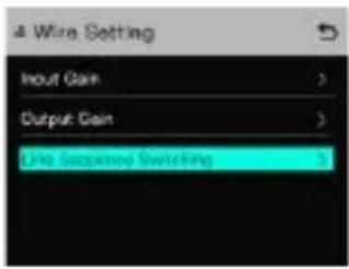 | 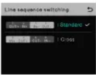 |
| HUB 2 | Enter “4 Wi re” menu, and select “Line sequenc e switching ” | Set to “Cross mode” |
| 4 Wire Settings | 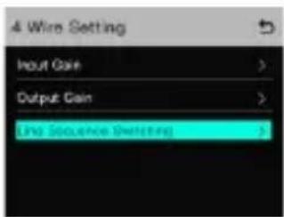 | 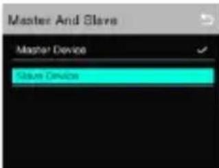 |
Two Systems Cascade via IP Network
Use a standard network cable to connect the two systems through the RJ45 network port. Either one of the two RJ45 network ports on the HUB works. The network cable is generally up to 300 meters long.
Quick Start Guide
HUB Settings
After connecting the two systems with the network cable, configure each HUB Base's basic settings as Master or Slave device. Generally, the first system is set as Master Device, and the second one as Slave Device.
In this case, you need to turn OFF the "Obtain IP address automatically" under "Network" settings on both the HUB Bases.
HUB Display Interfaces
| HUB 1 | Enter “Network” menu, and set the “Obtain IP address automatically” to OFF | Enter “Master and Slave” menu, and select “Master Device” |
| Network Settings | 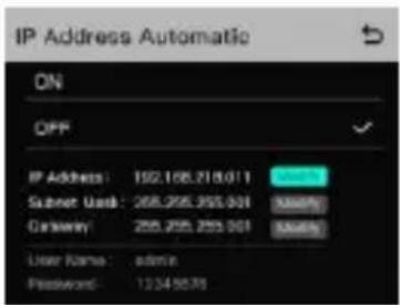 | 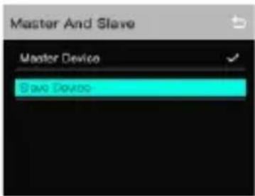 |
| HUB 2 | Enter “Network” menu, and set the “Obtain IP address automatically” to OFF | Enter “Master and Slave” menu, and select “Slave Device” |
| Network Settings | 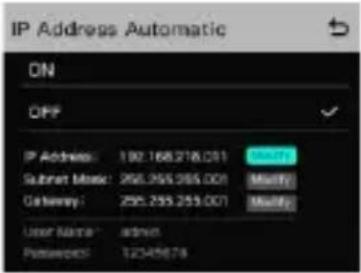 | 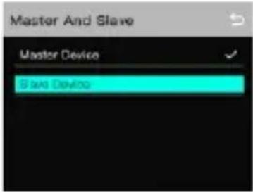 |
| Tap “Scan” to enter. The sc reen will display the Master Device’s IP address. Use the Arrow Key to locate the IP address, and press C onfirm. | 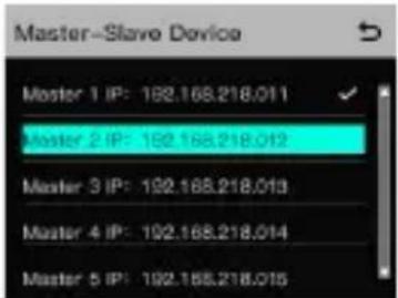 |
Three Systems Cascade via IP Network Cascade Connection Method
When cascading three systems, it is recommended to use the IP network connection. Set the first system's HUB to Master Device and the second and third HUBs to Slave Device.

Group Settings
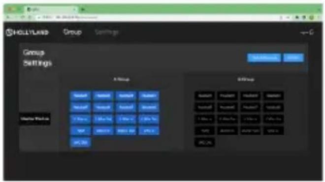
The HUB Base supports A and B grouping settings. You can view the system's current group setting by entering the Group menu on the HUB. To operate group settings, connect the computer and the HUB via the RJ45 interface using the network cable, and enter the Group settings menu. Or download the Solidcom APP on the mobile phone and connect to the HUB through WiFi to access the Group settings menu.
Check Group Settings on HUB
Viewing method:
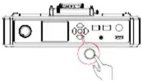
Long press the Menu/Confirm Button to enter the Group settings menu
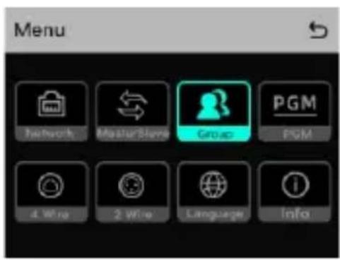
HUB Display Interfaces
Operate Grouping via Computer
Enter the "Network" menu on the HUB, and select "Wired network settings" to view the HUB's default IP Address, User Name and Password.
Use a network cable to connect the computer and the HUB via the RJ45 network port. Set the IP address of the computer as [192.168.218.xxx], and the default IP address of the HUB as [192.168.218.10]
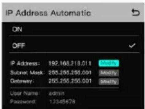
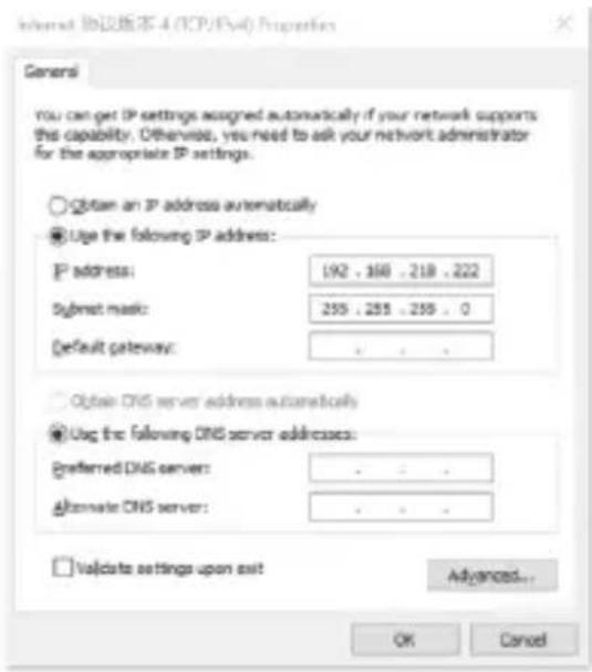
Quick Start Guide
Open the browser on the computer and visit http://192.168.218.10 to enter the configuration page of the HUB.
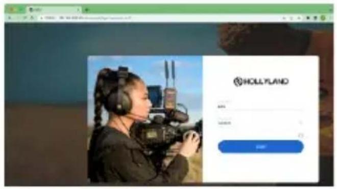
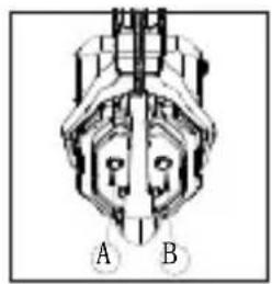
A & B Group Buttons on Headset(s)
After entering Group setting on the HUB, the A and B Buttons on the connected headset will light up. The buttons light status indicates which group the headset has joined. Press the A or B Button on the headset to Join/Enter the corresponding group.
natural_image
Diagram of a mechanical or electrical component with labeled sections A and B (no text or symbols beyond labels)| A and B Button Light Status | Status |
| Light ON | When the A or B Button lights ON, it indicates the headset has joined the corresponding group and can converse with the other headset(s) in the same group. |
| Light OFF | When the A or B Button lights OFF, it indicates the headset has exited the corresponding group. |
Parameters
| Range 350m (1000ft) Line-of-Sight | |
| Frequency Information | Frequency band: 1.9GHz DECT (varies by country and region)Modulation mode: GFSKTransmit power: <21dBm (125.9mW) (varies by country and region)Receiving sensitivity: <-90dBm |
| Transmission Latency | <35ms |
| Battery Capacity 700mAh (2.66Wh) Li-Ion battery | |
| Headset Runtime Remote headset: ≈10h | |
| Charging Time ≈2.5h | |
| Frequency Response | 150Hz~7kHz |
| Signal-to-Noise Ratio | >55dB |
| Distortion | <1% |
| Microphone Type Electret | |
| Maximum Input Sound Pressure Level | Electret |
| Output Sound Pressure Level | Typical 98±3dBSPL(at94dBSPL1kHz) |
| HUB Base Netweight ≈1300g (antennas excluded) | |
| Net Weight | ≈170g (batteries included) |
| Temperature Range | Working status: 0~+45°CStorage status: -20~+60°C |
Note: The frequency band and transmit power varies by country and region.
Safety Precautions
Do not place the headsets near or inside heating devices (including but not limited to microwave ovens, induction cookers, electric ovens, electric heaters, pressure cookers, water heaters, gas stoves) to prevent the battery from overheating and exploding.
Never use non-original charging cases, cables and batteries with the product.
The use of non-original spare parts may cause electric shock, fire, explosion or other dangers.
Support
If you encounter any problems in using the product or need any help, please contact Hollyland Support Team via the following ways:
If encounter any problems in using the product or need any help, please follow these ways to get more technical support:

Hollyland Products User Group

HollylandTech

HollylandTech

Support@hollyland-tech.com

www.hollyland-tech.com
Statement:
All copyrights belong to Shenzhen Hollyland Technology Co.,LTD.
Trademark Statement:
Without the written approval of Shenzhen Hollyland Technology Co.,LTD, no organization or individual may copy or reproduce part or all of the content of the text without authorization, and may not disseminate it in any form.
All representations, information, recommendations in this document do not constitute warranties of any kind, express or implied.
Note:
Due to product version upgrades or other reasons, this quick guide will be updated from time to time. Unless otherwise agreed, this document is provided as a guide for use only. All representations, information, recommendations in this document do not constitute warranties of any kind, express or implied.
FCC Requirement
Any changes or modifications not expressly approved by the party responsible for compliance could void the user's authority to operate the equipment. This device complies with Part 15 of the FCC Rules. Operation is subject to the following two conditions:
(1) this device may not cause harmful interference.
(2) this device must accept any interference received, including interference that may cause undesired operation.
FCC Radiation Exposure Statement:
The device has been tested and comply with FCC SAR limits.
Note: This equipment has been tested and found to comply with the limits for a Class B digital device, pursuant to Part 15 of the FCC Rules. These limits are designed to provide reasonable protection against harmful interference in a residential installation. This equipment generates, uses, and can radiate radio frequency energy, and if not installed and used in accordance with the instructions, may cause harmful interference to radio communications. However, there is no guarantee that interference will not occur in a particular installation. If this equipment does cause harmful interference to radio or television reception, which can be determined by turning the equipment off and on, the user is encouraged to try to correct the interference by one or more of the following measures:
– Reorient or relocate the receiving antenna.
– Increase the separation between the equipment and receiver.
- Connect the equipment into an outlet on a circuit different from that to which the receiver is connected.
- Consult the dealer or an experienced radio/TV technician for help.
- Solidcom C1 - HUB8S Headset Intercom Package
- Product Interfaces
- A HUB Base Interfaces
- B Headset Interfaces
- Charging Case Interfaces
- Set Up HUB Base
- Power Up HUB Base
- Quick Start Guide
- Mute/Unmute Microphone
- HUB Base Main Display Interfaces
- Headset Status Indicator
- Pairing Operation
- Connect the HUB Base and the Headset with a USB-C Cable.
- Headset(s) Number Setting via HUB Base
- Cascade Connections
- Two Systems Cascade via 4-Wire Interface
- Wire Settings
- Two Systems Cascade via IP Network
- HUB Settings
- Group Settings
- Check Group Settings on HUB
- Operate Grouping via Computer
- A & B Group Buttons on Headset(s)
- Parameters
- Safety Precautions
- Support
- Statement:
- Trademark Statement:
- Note:
- FCC Requirement
Brand : Hollyland
Model : Solidcom C1-4S
Category : Intercom system