Racer BTCS006 - Saw Batavia - Free user manual and instructions
Find the device manual for free Racer BTCS006 Batavia in PDF.

| Brand | Batavia |
| Model | Racer BTCS006 (BT-CS006) |
| Product type | Precision circular saw (mini circular saw) |
| Power supply | 230-240 V~, 50 Hz |
| Power consumption | 450 W |
| No-load speed (variable) | 1000 – 2100 min⁻¹ |
| Max cutting depth | 20 mm |
| Blade diameter | 70 mm |
| Blade bore | 11.3 mm |
| Weight | 1.6 kg |
| Protection class | II (double insulation) |
| Sound pressure level | 87.54 dB(A) (K=3 dB(A)) |
| Sound power level | 98.54 dB(A) (K=3 dB(A)) |
| Vibration (main handle) | 2.199 m/s² (K=1.5 m/s²) |
| Vibration (additional handle) | 1.577 m/s² (K=1.5 m/s²) |
| Included accessories | 1 TCT blade 18 teeth ∅70 mm, 1 HSS blade 44 teeth ∅70 mm, hex key, suction hose, set of carbon brushes |
| Safety | Spring-loaded lower guard, spindle lock, overload protection, safety switch |
| Maintenance and cleaning | Clean with a damp cloth and black soap; replace carbon brushes by a professional; blow out ventilation slots |
| Warranty | 2 years (material and workmanship defects) |
| Intended use | Sawing wood, similar materials, plastics; tiles with diamond disc; only dry use; not for professional or industrial use |
Frequently Asked Questions - Racer BTCS006 Batavia
User questions about Racer BTCS006 Batavia
0 question about this device. Answer the ones you know or ask your own.
Ask a new question about this device
Download the instructions for your Saw in PDF format for free! Find your manual Racer BTCS006 - Batavia and take your electronic device back in hand. On this page are published all the documents necessary for the use of your device. Racer BTCS006 by Batavia.
USER MANUAL Racer BTCS006 Batavia
Operating instructions
Gebruiksaanwijzing
Mode d'emploi
natural_image
Exterior view of a BATAVIA electric shaver with open grip and orange handle (no text or symbols visible)Modelnr. BT-CS006
Art.Nr. 7060453
- Glossery of symbols....18
- Safety instructions....18
- Component description and scope of supply..25
- Intended use 25
- Technical data 25
- Using for the first time 26
- Operation 27
- Cleaning and maintenance 28
- Repair and ordering of spare parts 29
- Disposal and recycling 29
- EC-Declaration of conformity 29
Inhoudsopgave
natural_image
Close-up of a robotic hand cutting a thin wire on a surface, no visible text or symbolsnatural_image
3D model of a futuristic vehicle with labeled parts (4, 11) and directional arrows, no readable text or symbols beyond labels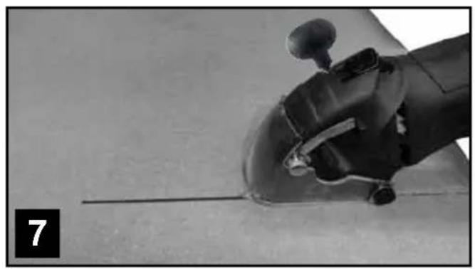
natural_image
Close-up of a robotic arm gripping a tool, with no visible text or symbols1. GLOSSARY OF SYMBOLS

WARNING - To reduce the risk of injury during operation, read the instructions.

Always wear hearing protection. The effects of noise can cause hearing loss.

Wear a dust mask. When working with wood and other materials, harmful dust may be generated. Work with asbestos-containing materials is not permitted!

Wear safety glasses. When working with electric power tools, sparks, splinters, chips and dust particles may be generated and these can cause loss of sight.

General warning signs – Be attentive and look out for any possible danger.

Command signs – Wear protective footwear!

Command signs – Wear safety gloves!

Electric power tool, protection class II

The manufacturer uses the CE marking to confirm that this electric power tool complies with the relevant European directives.

Not for wet grinding!

Not for rough grinding!
2. SAFETY INSTRUCTIONS
2.1 GENERAL SAFETY INSTRUCTIONS FOR POWER TOOLS

WARNING! Read all instructions
Failure to follow all instructions listed below may result in electric shock, fire and/or serious injury.
The term “power tool” in all of the warnings listed below refers to your mains operated (corded) power tool or battery operated (cordless) power tool.
Save these instructions for future reference!
1. Work area
a) Keep work area clean and well lit.
Cluttered and dark areas invite accidents.
b) Do not operate power tools in explosive atmospheres, such as in the presence of flammable liquids, gasses or dust.
Power tools create sparks which may ignite the dust of fumes.
c) Keep children and bystanders away while operating a power tool.
Distractions can cause you to lose control.
2. Electrical safety
a) Power tool plugs must match the outlet. Never modify the plug in any way. Do not use any adapter plugs which earthed (grounded) power tools.
Unmodified plugs and matching outlets will reduce risk of electric shock.
b) Avoid body contact with earthed or grounded surfaces such as pipes, radiators, ranges and refrigerators.
There is an increased risk of electric shock if your body is earthed or grounded.
c) Do not expose power tools to rain or wet conditions.
Water entering a power tool will increase the risk of electric shock.
d) Do not abuse the cord. Never use the cord for carrying, pulling or unplugging the power tool. Keep cord away from heat, oil, sharp edges or moving parts.
Damaged or entangled cords increase the risk of electric shock.
e) When operating a power tool outdoors, use an extension cord suitable for outdoor use.
Use of a cord suitable for outdoor use reduces the risk of electric shock.
f) Always use tool in conjunction with a residual circuit breaker device. The use of a residual circuit breaker device reduces the risk of electric shock.
3) Personal safety
a) Stay alert, watch what you are doing and use common sense when operating a power tool. Do not use a power tool while you are tired or under the influence of drugs, alcohol or medication.
A moment of inattention while operating power tools may result in serious personal injury.
b) Use safety equipment. Always wear eye protection.
Safety equipment such as dust mask, non-skid safety shoes, hard hat, or hearing protection used for appropriate conditions will reduce personal injuries.
c) Avoid accidental starting. Ensure the switch is in the off position before plugging in.
Carrying power tools with your finger on the switch or plugging in power tools that have the switch on invites accidents.
d) Remove any adjusting key or wrench before turning the power tool on.
A wrench or a key left attached to a rotating part of the power tool may result in personal injury.
e) Do not overreach. Keep proper footing and balance at all times.
This enables better control of the power tool in unexpected situations.
f) Dress properly. Do not wear loose clothing or jewellery. Keep your hair, clothing and gloves away from moving parts.
Loose clothes, jewellery or long hair can be caught in moving parts.
g) If devices are provided for the connection of dust extraction and collection facilities, ensure these are connected and properly used.
The use of these pieces of equipment reduce hazards caused by dust.
- Power tool use and care
a) Do not force the power tool. Use the correct power tool for your application.
The correct power tool will do the job better and safer at the rate for which it was designed.
b) Do not use the power tool if the switch does not turn it on and off.
Any power tool that cannot be controlled with the switch is dangerous and must be repaired.
c) Disconnect the plug from the power source before making any adjustments, changing accessories, or storing power tools.
Such preventive safety measures reduce the risk of starting the power tool accidentally.
d) Store idle power tools out of the reach of children and do not allow persons unfamiliar with the power tool or these instructions to operate the power tool.
Power tools are dangerous in the hands of untrained users.
e) Maintain power tools. Check for misalignment or binding of moving parts, breakage of parts and any other condition that may affect the power tools operation.
If damaged, have the power tool repaired before use. Many accidents are caused by poorly maintained power tools.
f) Keep cutting tools sharp and clean.
Properly maintained cutting tools with sharp cutting edges are less likely to bind and are easier to control.
g) Use the power tool, accessories and tool bits etc., in accordance with these instructions and in the manner intended for the particular type of power tool, taking into account the working conditions and the work to be performed.
Use of the power tool for operations different from intended could result in a hazardous situation.
- Service
a) Please use a qualified expert who uses original replacement parts to repair your power tool.
This will ensure proper functioning of the power tool.
2.2 SAFETY INSTRUCTIONS FOR ALL SAWS
a) DANGER: Do not put your hands in the sawing area or on the saw blade. Use your second hand to hold onto the auxiliary handle or the motor housing. If both hands are being used to hold the circular saw, then they cannot be injured by the saw blade.
b) Do not grip underneath the workpiece. The safety guard cannot protect you against the saw blade under the workpiece.
c) Adjust the cutting depth to the thickness of the workpieces. The saw should protrude by no more than the height of one tooth under the workpiece.
d) Never hold the workpiece to be sawn in your hand or over your leg. Secure the workpiece in a stable holder. It is important to fasten the workpiece firmly in order to minimise the danger of contact with the body, jamming of the saw blade or loss of control.
e) Grip the electric power tool by the insulated handling surfaces only when you are carrying out work in situations where the tool insert may make contact with hidden power lines or its own power cable. Contact with a live wire places a voltage on the metal parts of the electric power tool and will lead to an electric shock.
f) Always use a stop or a straight edge guide when making longitudinal cuts. These improve the accuracy of the cut and reduce the possibility of the saw blade jamming.
g) Always use saw blades of the right size and with matching locating holes (e.g. star-shaped or round). Saw blades which are not matched to the mounting pieces of the saw will run eccentrically and lead to loss of control.
h) Never attach the saw blade using damaged or incorrect washers or screws. The saw blade washers and screws are specially constructed for your saw, to give optimal performance and operating safety.
2.3 ADDITIONAL SAFETY INSTRUCTIONS FOR ALL SAWS
The causes of kickback and how to avoid them:
- A kickback is a sudden reaction due to snagging, jamming or misalignment of the saw blade, which results in the uncontrolled saw jumping out of the workpiece and moving towards the operator.
- If the saw blade having snagged or jammed in a self-closing saw cut, is locked and the motors power jolts the device back towards the operator.
- If the saw blade is rotated or misaligned in the saw cut, the teeth on the rear edge of the blade can become hooked in the surface of the workpiece, whereby the saw blade jumps out of the cut and the saw springs back in the direction of the operator.
A kickback is the result of improper or incorrect use of the saw. It can be avoided by taking suitable precautions, as described below.
a) Hold the saw firmly with both hands and place your arms in such a position that you can absorb the force of a kickback. Always keep yourself to one side of the saw blade and never bring the blade in line with your body. In the event of a kickback, the circular saw may spring backwards; however, the operator can control the kickback force if suitable measures have been taken.
b) If the saw blade becomes jammed or if you interrupt the work, switch the saw off and keep it held gently in the material until the saw blade has come to rest. Never attempt to extract the saw from the workpiece or to pull it backwards while the saw blade is moving; otherwise a kickback may occur. Find and remove the cause for the saw-blade's jamming.
c) If you wish to restart a saw that is already in the workpiece, centre the saw blade in the cut and check that the teeth are not snagged in the workpiece. If the saw blade jams, it may run out of the workpiece or cause a kickback when the saw is restarted.
d) Provide support for large sheets to reduce the risk of a kickback through jamming of the saw blade. Large sheets can bend under their own weight. The sheets must be supported on both sides, at the edges and close to the saw cut.
e) Do not use blunt or damaged saw blades. If saw blades with blunt or misaligned teeth are used, the saw cut is too narrow resulting in increased friction, jamming of the blade and kickback.
f) Before sawing, firmly tighten the adjustments of the cutting depth and cutting angle. If the settings adjust themselves during sawing, the saw blade may become clamped and a kickback will occur.
g) Be especially careful, if you are making a plunge cut in an existing wall or other non-visible area. The immersed saw blade can jam when sawing into hidden objects and cause a kickback.
2.4 SAFETY INSTRUCTIONS FOR THIS MINI CIRCULAR SAW
a) Check before each use that the safety guard closes correctly. Do not use the saw if the lower safety guard does not move freely and does not close immediately. Never clamp or secure the lower safety guard in the open position.
If the saw should accidentally fall to the ground, the lower safety guard may become bent. Open the safety guard with the retraction lever and ensure that it moves freely. Check that it does not interfere with the saw blade or other components, at any cutting angle or cutting depth.
b) Check the condition and operation of the spring for the lower safety guard. Do not use the equipment if the lower safety guard and spring do not work perfectly. Damaged parts, adhesive deposits or accumulations of shavings retard the operation of the lower safety guard.
c) When making a plunge cut which is not at right angles, make sure that the saw's guide plate can not move laterally. Lateral movements can cause the saw blade to jam and hence result in kickback.
d) Do not put down the saw on the workbench or floor, without the lower safety guard covering the saw blade.
When slowing down after use, an unprotected saw blade will move the saw in the direction opposite to the cutting direction and will saw whatever lies in its path. Pay attention, therefore, to the deceleration time of the saw.
2.5 SAFETY INSTRUCTIONS FOR CUT OFF GRINDING APPLICATIONS
Safety instructions for cut off grinders
a) The safety guard for the electric power tool must be securely attached and adjusted so that maximum safety is attained, i.e. the smallest possible portion of the grinding wheel shows openly to the operator. Make sure that you and any other nearby individuals are not in the plane of the rotating grinding disc. The safety guard is intended to protect the operator from fragments and from accidental contact with the grinding wheel.
b) Use only diamond cutting discs for your electric power tool. The fact that you can attach an accessory to your electric power tool, does not guarantee that it is safe to use.
c) The permissible rotary speed of the tool insert must be at least as high as the quoted maximum rotary speed of the electric power tool. Accessories which are rotated faster than their permissible speed may break or fly off.
d) Grinding wheels may only be used for their recommended types of application, e.g. never grind with the side face of a cutting wheel. Cutting wheels only remove material using the edge of the disc. Application of lateral forces to these grinding wheels can cause them to break.
e) Always use an undamaged clamping flange of the correct size and shape for your selected grinding disc. Suitable flanges support the grinding disc and so reduce the danger of it breaking.
f) Do not use worn out grinding discs from larger electric power tools. Grinding discs from larger electric power tools are not suitable for the higher rotary speeds of small electric power tools and can break during use.
g) The outer diameter and thickness of tool inserts must correspond with the given characteristics of your electric power tool. Wrongly-sized tool inserts cannot be sufficiently shielded or controlled.
h) Grinding discs and flanges must fit exactly on the grinding spindle of your electric power tool. Tool inserts, which do not fit exactly to the grinding spindle of the electric power tool, will rotate unevenly and vibrate strongly and may lead to loss of control.
i) Do not use damaged grinding discs. Before each use, inspect the grinding wheels for any chipping or cracks. If the electric power tool or the grinding disc is dropped, inspect it for damage or replace it with an undamaged grinding disc. When you have inspected and installed the grinding disc, make sure that you, and any other nearby individuals, remain out of the plane of the rotating grinding disc and then allow the tool to rotate at its highest speed for one minute. Damaged grinding discs usually break during this test time.
j) Wear protective clothing and equipment. Depending on the application, use either a full face visor, protective goggles or safety glasses. As far as appropriate, where a dust mask, hearing protection, safety gloves or special apron to protect yourself from splinters and other particles of material.
The eyes must be protected against any flying particles which may be generated during the various applications. Dust masks or respirators must filter out the dust generated by the application. If you are exposed to loud noise for a long time, you may suffer from hearing loss.
k) Make sure that other people remain at a safe distance from your working area. Anyone entering the work area must wear personal safety clothing and equipment.
Fragments of the workpiece or of a broken tool insert may fly off and cause injuries, even outside the direct working area.
I) If you are carrying out work in situations where the tool insert may make contact with concealed power lines or its own power cable, only hold the device by the insulated hand grips. Contact with a live cable could result in metal parts of the device also becoming live and lead to an electric shock.
m) Keep the power cable and the rotating tool insert far apart. If you lose control of the device, the power cable may be severed or caught and may draw your hand or arm into the rotating tool insert.
n) Never put down the electric power tool before the tool insert has come to a complete stop. The rotating tool insert may come into contact with the supporting surface and cause you to lose control of the electric power tool.
o) Do not leave the electric power tool running while you carry it around. Your clothes may become caught through accidental contact with the rotating tool insert and result in the tool drilling into your body.
p) Clean the ventilation slits on your electric power tool, regularly. The motor fan draws dust into the housing and a large accumulation of metallic dust can cause electrical hazards.
q) Do not use the electric power tool in the vicinity of flammable materials. Sparks can ignite such materials.
r) Do not use any tool inserts which require liquid coolants. The use of water or other liquid coolants could result in electrical shock.
2.6 FURTHER SAFETY INSTRUCTIONS FOR CUT OFF GRINDING APPLICATIONS Kickback and relevant safety instructions
Kickback is the sudden reaction following snagging or jamming of a rotating grinding disc. Snagging or jamming lead to an abrupt stop of the rotating tool insert. This may then cause the uncontrolled electric power tool to accelerate in the opposite direction to the inserted tools direction of rotation at the point were it jammed. If, for example, a grinding disc snags or jams inside a workpiece, the edge of the grinding disc which is inside the workpiece may become caught and thus cause the grinding disc to jump out or create a kickback. The grinding disc then moves towards or away from the operator, depending on the direction of rotation of the disc at the jamming point. This can also cause a grinding disc to break. A kickback is the result of improper or incorrect use of the electric Power tool. It can be avoided by taking suitable precautions, as described below.
a) Hold the electric power tool firmly and place your body and arms in such a position that you can absorb the force of a kickback. Always use the auxiliary grips, when available, in order to have the greatest possible control over kickback forces or torque reactions at high speed. By taking suitable precautionary measures, the operator can control kickback and reaction forces.
b) Never bring your hand into the vicinity of a rotating tool insert. The inserted tool could move over your hand if kickback occurs.
c) Avoid the area in front of and behind a rotating cutting wheel. A kickback will send the electric power tool in the opposite direction to the movement of the grinding disc at the point where it jams.
d) Work extremely carefully in the neighbourhood of corners, sharp edges etc. Prevent the tool insert from recoiling from the workpiece and jamming. The rotating tool insert bends at corners and sharp edges or if it rebounds and may jam itself. This causes a loss of control or kickback.
e) Do not use any chainsaw or toothed saw blade, nor any segmented diamond disc, with slots wider than 10 mm. Such tool inserts frequently cause a kickback or loss of control of the electric power tool.
f) Avoid jamming of the cutting wheel or too high a contact pressure. Do not make excessively deep cuts. An overload of the cutting wheel increases its stress and its susceptibility to tilting or jamming and, hence, increases the possibility of a kickback or break in the grinding wheel.
g) If the cutting wheel becomes jammed or if you interrupt the work, switch the device off and keep it held gently until the disc has come to a standstill. Never attempt to remove a still-running cutting wheel from the cut, otherwise kickback may result. Find and remove the cause for the jamming.
h) Do not switch on the electric power tool again, while it is still in the workpiece. Allow the cutting wheel to first reach its full rotation speed before carefully continuing the cut; otherwise, the disc may snag, jump out of the workpiece or cause a kickback.
i) Provide support for large workpieces, to reduce the risk of a kickback through jamming of the cutting wheel. Large workpieces can bend under their own weight. The workpiece must be supported on both sides of the disc, as well as both in the neighbourhood of the separation cut and at the edges.
j) Be especially careful when making "pocket cuts" in existing walls or other non-visible areas. The immersed cutting tool can cause a kickback when cutting into gas or water pipes, electric cables or other objects.
2.7 SAFETY AND OPERATING INSTRUCTIONS FOR DIAMOND GRINDING WHEELS
Use
Only use the cut off grinding disc for cut off grinding and not for rough grinding! Only use the cut off grinding discs for the materials indicated and not for any other materials. Risk of injury! Cutting and cooling!
General Information
This tool insert is fragile, therefore extreme care is required when handling it. The use of damaged and incorrectly tensioned or installed tool inserts is dangerous and can result in serious injury.
Handling and storage
Tool inserts must be carefully handled and transported. Tool inserts should be stored in such a way that they are not exposed to any mechanical damage or damaging environmental influences.
To avoid damage, remove the tool insert before transporting an electric power tool.
Selection and safe and proper use
Pay attention to the data on the label or on the tool insert, such as the restrictions on use, safety instructions or other advice. Do not alter the characteristic direction of motion of the tool insert. If there is ambiguity over the selection of tool inserts, contact the manufacturer or a specialist. Adhere to the permissible rotation speeds for the tool insert and the electric power tool.
Before use
Tool inserts must be given a visual inspection before each start-up. Do not use damaged tool inserts. Secure the piece to be worked on.
Inserting and changing
Tighten the tool inserts in accordance with their instructions and those of the electric power tool's manufacturer. The tightening of tool inserts should only be undertaken by qualified persons. After each tightening, carry out a test run for a suitable length of time, during which the characteristic maximum working speed of the tool insert may not be exceeded.
Always tighten tool inserts without introducing any out-of-roundness.
Use
- Pay attention to the operating instructions of the electric power tool with which you are using the tool insert.
- Before start-up, attach an appropriate safety device to the electric power tool. Do not carry out any work without protection provided through safety devices.
- Use personal protective clothing and equipment suitable for the type of machine used and the application undertaken, e.g. eye and face protection, hearing protection, respirators, safety shoes, safety gloves and other protective clothing.
- Only undertake work for which the tool insert is suitable (taking into consideration use restrictions, safety instructions and other data).
- Switch off the electric power tool before placing it on the workbench or on the floor and wait until the tool insert is stationary.
- For cut off grinding, place the tool insert directly in the gap, so that the electric power tool does not tilt.
- Do not go backwards and forwards in the material, rather pull the tool calmly through it.
- Work only at right angles and in straight lines, to avoid the danger of cracking in the core or segments breaking off.
- Do not exert a strong grinding pressure; the weight of the electric power tool will suffice.
- Do not include any cooling breaks.
- Caution! The tool insert will become very hot during the work; only touch it with safety gloves, after it has cooled down.
2.8 SAFETY INSTRUCTIONS FOR HANDLING SAW BLADES
- Only use tool inserts if you are familiar with their handling.
- Do not exceed the maximum rotation speed The maximum permissible rotation speed indicated on the tool insert must not be exceeded. Remain within the rotation speed range, if indicated.
- Do not use cracked tool inserts. Throw away any cracked tool inserts. Repair is not permitted.
- Clean off any contamination, fat, oil or water from the clamping surfaces.
-
Do not use any loose spacers or bushes to reduce the size of the holes in the circular saw blades.
-
Make sure that fixed spacers for securing the tool inserts have the same diameter and at least 1/3 of the cutting wheel diameter.
- Make sure that any fixed spacer rings are parallel to one another.
- Handle the tool inserts with care. Preferably, store these in their original packaging or in special containers. Wear safety gloves to improve safe gripping and to further reduce the risk of injury.
- Before using the tool inserts, make sure that all the safety devices are suitably fastened.
- Make sure before use, that the tool insert you are going to use corresponds to the technical requirements of this electric power tool and is suitably fastened.
- Only use the saw blade provided when working with wood; never use it for working with metals.
2.9 RESIDUAL RISKS
Even when you use this electric power tool correctly, residual risks remain. The following dangers may arise in connection with the construction and application of electric power tools, among other things:
- Damage to health resulting from hand-arm vibrations if the electric power tool is used over a long period of time, or is incorrectly operated or maintained.
- Injuries or damage to property, caused by flying tool inserts, which unexpectedly spin out of the electric power tool due to sudden damage, wear or incorrect mounting.
- Burns and cuts, in cases where the tool inserts are brought into contact with bare skin immediately after use.
Warning! These electric power tools produce an electromagnetic field during operation. Under certain circumstances, this field may impair the operation of active or passive medical implants. In order to reduce the danger of serious or fatal injuries, we recommend that persons with medical implants consult their doctor and the manufacturer of the medical implant before operating the electric power tool.
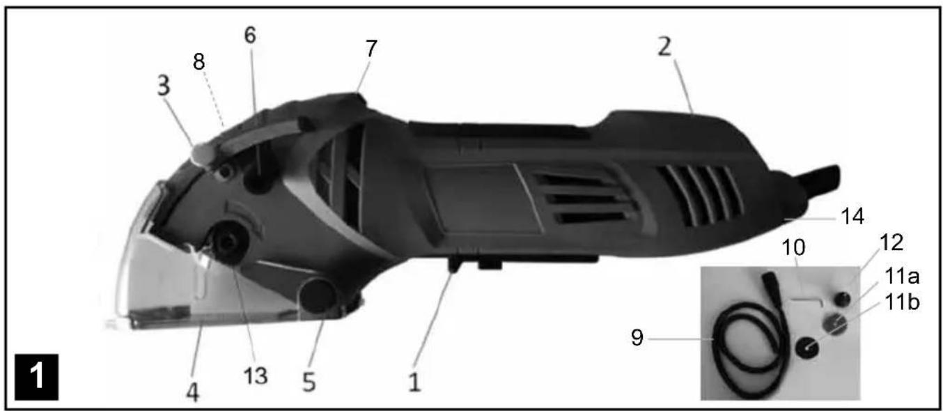
3. COMPONENT DESCRIPTION AND SCOPE OF SUPPLY (FIGURE 1)
- On/Off switch
- Overload indicator
- Cutting depth limiter
- Safety guard
- Hinge axis of the safety guard
- Dust extraction connection
- Release button for the safety guard
- Spindle lock
- Vacuum hose
-
Allenkey
-
Tool inserts
a) 1 x TCT saw blade with 18 teeth,
∅ 70 x ∅ 11.3 mm
b) 1 x HSS blade with 44 teeth,
∅ 70 x ∅ 11.3 mm
12.Auxiliaryhandle
-
Clampingscrew
-
Adjustment dial for the rotation speed
15.1x carbon brush set
4. INTENDED USE
The mini hand-held circular saw is suitable for sawing straight-line cuts in wood, wood-like materials and plastics. For these cuts, use either the carbide tipped saw blade or the HSS saw blade. Cutting tiles, printed circuit boards and glass fibre reinforced plastics is possible using the diamond cutting discs.
All work can only be carried out in dry conditions. The electric power tool may only be used in accordance with its specification. It is not intended for any other use above and beyond these. The user or operator, and not the manufacturer, is responsible for any resultant damage or injuries of any kind.
Please note that our electric power tools are not designed for commercial, trade or industrial use. We provide no warranty if the electric power tool is used for commercial, trade or industrial applications or activities equivalent to these.
5. TECHNICAL DATA
Power connection 230-240 V\~
Frequency 50 Hz
Power consumption 450 W
No load speed n_0 1000 - 2100 min ^-1
Max. cutting depth max. 20 mm
Saw blade ∅ 70 mm
Saw blade holder ∅ 11.3 mm
Safety class II / double insulation
Weight 1.6 kg
Sound pressure level L_pA 87.54 dB(A)
Uncertainty K_pA 3 dB(A)
Sound power level L_WA 98.54 dB(A)
Uncertainty K_WA 3 dB(A)

External diameter: ∅ 70 mm
Bore diameter: ∅ 11.3 mm
Strength: 2 mm
Number of teeth/segment: 18
Max. permissible rotation speed: 5200 min ^-1
Cutting materials group:
Hard metal or Tungsten Carbide (HW)
Application: Saw work
Material: Wood

External diameter: ∅ 70 mm
Bore diameter: ∅ 11.3 mm
Strength: 0.8 mm
Number of teeth/segment: 44
Max. permissible rotation speed: 5200 min ^-1
Cutting materials group: HW
Application: Saw work
Material: Wood, wood-like materials, plastics
Noise and vibration
The noise and vibration values are determined according to EN 60745-1 and EN 60745-2-5.
Handle
Hand-arm vibration when sawing wood
$$ a _ {h, W} = 2. 1 9 9 \mathrm{m} / \mathrm{s} ^ {2} $$
Uncertainty K = 1.5 m/s ^4
Auxiliary handle
Hand-arm vibration when sawing wood
$$ a _ {h, W} = 1. 5 7 7 \mathrm{m} / \mathrm{s} ^ {2} $$
Uncertainty K = 1.5 m/s ^2

Attention!
The stated vibration emission was determined using a standardised measurement technique and allows comparisons between this tool and others. The stated vibration emission can also act as a preliminary risk estimate. The actual vibration emission during tool use may deviate from the indicated values, depending on how the tool is used. Based on the estimated risk under realistic conditions, suitable preventative measures should be taken to protect the user (The load run times for all the working cycles should also be considered such as, for example, continued turning and idling of the tool).
Limit noise and vibration to a minimum!
• Use only problem free electric power tools.
• Regularly maintain and clean the electric power tool.
- Adapt your working methods to the electric power tool.
• Do not overload the electric power tool.
• Have the electric power tool inspected, if necessary.
- Switch the electric power tool off when it is not in use.
6. USING FOR THE FIRST TIME
6.1 Unpacking
- Open the packaging and carefully remove the electric power tool.
- Remove the packaging material.
- Remove the packing and transport safety devices (if any).
- Check that all the expected contents are present.
- Inspect the electric power tool and accessories for any damage during transport.
- Retain the packaging, if possible, until the end of the warranty period. Thereafter, please dispose of the packaging in an environmentally friendly way, by utilising a recycling system.
6.2 Connection to the power supply
Make absolutely sure, before connecting, that the data on the nameplate agrees with the mains power supply data. Always pull out the power plug before making adjustments to the electric power tool.
6.3 Note

Attention!
• Before undertaking any work on the electric power tool, unplug it from the mains!
- Do not use tool inserts which are defective or which exhibit tears or fissures.
- Do not use a flange or flange nut with a hole larger or smaller than the hole in the tool insert.
- Only use tool inserts of the same type as those delivered with the electric power tool. Seek advice from a specialist trader.
6.4 Inserting and changing tool inserts (figures 3 and 4)
- Press the spindle lock (8).
- Loosen the clamping screw (13) by turning it clockwise with the Allen key (10).
- Press the lock on the safety guard (7), push back the movable safety guard and hold it firmly.
• If the tool insert (11) is clamped, move it downwards. - Clean the flange and install a new tool insert. Pay attention to the direction of motion (check the arrows on the housing and on the tool insert).
- Tighten the clamping screws, anticlockwise, to secure the tool insert, ensuring that the tool insert is concentric.
- Before you operate the on/off switch, make sure that the tool insert is correctly installed, that the moving parts are free and the clamping screws are firmly tightened.
- Attention! The Allen key (10) must not be left inserted in the clamping screw.
Note: After installing or changing a tool insert, allow the electric power tool to run for the first minute without any load, in order to make sure that the tool insert is correctly seated.
6.5 Setting the cutting depth (Figure 5)
- Loosen the adjustment screw (3).
- Adjust the cutting depth according to the scale (a) and tighten the adjustment screw (3).
- For wood and plastics, the cutting depth should be selected to be a little deeper than the material thickness.
- A wood underlay can be used to achieve a better cutting quality. The wood underlay will, however, be damaged.
6.6 Extraction of dust and splinters (Figure 6)
Attention! When working with items coated in lead-containing paint, for example, or with some types of wood, harmful or poisonous dust particles may be generated. This presents a danger both for the user and for other people nearby. Protect yourself with suitable personal safety clothing and equipment and keep other people away from the working area.
Connect an extraction system or a vacuum cleaner to the electric power tool. This will provide you with optimum extraction of dust and splinters from the workpiece.
Advantages: You preserve both the electric power tool and your health. Moreover, you're working area remains clean and safe.
- Connect the suction hose (9) to the dust extraction connection (6).
- Make sure that the seal inside the smaller of the connecting pieces on the hose (9) fits on to the dust extraction connection (6).
- Turn the suction hose to the right until it engages.
Attach a suitable dust extraction device.
Notes:
- Make sure that the vacuum cleaner is suitable for use with the electric power tool. Most dry vacuum cleaners for domestic use are well-suited to this purpose.
- The vacuum cleaner is particularly useful if many cuts are being performed successively. It means that less frequent stops are required to clean the electric power tool and the workplace.
- When you are cutting materials which may produce dangerous dust, always use a vacuum cleaner. This applies, in particular, to hardwoods, MDF sheets and ceramics.
6.7 Auxiliary handle (Figure 4)
Screw the auxiliary handle (12) into the attachment point on the upper side of the housing.
Attention! Always use the electric power tool with the auxiliary handle attached.
7. OPERATION
7.1 General instructions
- Select a suitable tool insert for the material that is to be worked on.
- Check the condition and sharpness of the tool insert.
• Always hold the electric power tool with a firm grip. - Exert no force! Push the electric power tool forwards, gently and evenly.
- The electric power tool must not be braked with the hand or by applying lateral pressure.
- The safety guard may not be blocked and must be returned to the starting position after the final working step.
- Before use of the electric power tool, inspect the function of the safety guard with the tool unplugged from the mains.
- Before each use of the electric power tool, make sure that the safety mechanisms such as the safety guard, flanges and adjustment devices are functioning and/or are correctly installed and fastened.
- A suitable dust extraction system is to be connected to the dust extraction connection (6). Make sure that the dust extraction is correctly and securely attached.
7.2 Set the rotation speed
- Before starting work, set a suitable rotation speed for the application. For example, when working with soft materials a higher rotation speed will be set than for hard materials.
- To adjust the rotation speed, turn the adjustment wheel (14) according to the application. For the lowest rotation speed set the wheel to "1"; the maximum rotation speed is achieved with a setting of "6".
7.3 Switching On and Off
Switching on: Slide the On/Off switch (1) towards the rear, press and hold.
Switching off: Release the On/Off switch (1).
7.4 Overload protection
The electric power tool is equipped with an overload protection. The overload indicator (2) displays the operating condition of the electric power tool.
Overload indicator (2) flashing: The electric power tool is approaching the limiting load – reduce the
forward feed speed.
Overload indicator (2) continually lit: The electric power tool is overloaded or jammed - the electric power tool cuts out. In this event, switch the electric power tool off and allow it to cool down before using it again.
7.5Use

Warning! Always begin by making a test cut in a left-over piece.
- Firmly clamp small wooden pieces before commencing work. Never hold them in your hand.
• Fully observe the safety regulations! Wear safety glasses! - Adjust the cutting depth and rotation speed.
- Pick up the electric power tool and make sure that none of the ventilation openings are covered.
- Switch on the electric power tool and wait for several seconds until the tool insert has attained its full rotation speed.
- The waste piece should be on the right or left side of the electric power tool, so that the wide part of the supporting table rests on its entire surface.
- The base plate must always rest flat on the workpiece.
- Press the release button (7) and slowly push the tool insert into the workpiece or, if necessary, plunge it.
- Push the electric power tool forwards through the workpiece. Never move it backwards!
- Apply only a gentle force to the electric power tool when working.
- If sawing along a marked line, lead the electric power tool along the appropriate groove.
- If the overload indicator (2) flashes, reduce your speed.
- If the electric power tool stops and the overload indicator (2) is lit continuously, then the overload protection of the electric power tool has responded. Reason: You were moving forward too quickly or have encountered an obstacle in the workpiece. In this case, switch off the electric power tool and inspect the workpiece. Move forward at a slower speed.
7.6 Line cuts (Figure 7)
You can follow a drawn line with the help of the indicator marks (a), at the front and rear of the safety guard. For precise work, the relationship between the saw cut and a marked indicator line must be established using a test piece. The ideal positioning of the saw cuts must then be achieved by adjusting the indicator line to the target line.
7.7 Working with large workpieces
When working with large workpieces or cutting straight edges:
- Use fastening clamps to tighten a board or border onto the workpiece as an auxiliary stop.
- Guide the left-hand side of the base plate along the auxiliary stop.
7.8 Plunge cuts (Figure 4)
Note: Some very hard materials are not suitable for plunge cuts.
Put the base plate on the workpiece. Make sure that the rear lateral depth marking is at the height of the beginning of the cut.
Switch on the electric power tool and allow a couple of seconds to pass until the tool insert reaches its full speed.
Then plunge the tool insert, slowly but with some pressure. Push the electric power tool forwards through the workpiece.
When you reach the end of the cut, switch off the electric power tool and pull it out of the workpiece.
7.9 Cutting tiles
Adhesive tape or insulation tape on the workpiece makes the work easier and helps to prevent it from getting scratched.
8. CLEANING AND MAINTENANCE

Warning! Pull out the power plug before any cleaning work.
Cleaning
- Keep safety devices, ventilation openings and the motor housing as free as possible from dirt and dust. Rub the electric power tool with a clean cloth or blow over it with low pressure compressed air.
• We recommend that you clean your electric power tool immediately after each use.
- Clean the electric power tool regularly with a damp cloth and somewhat soft soap. Do not use any cleaning or solvent materials; these can attack the device's plastic components. Make sure that no water can get inside the electric power tool.
Carbon brushes
In the event of excessive sparking, allow a qualified person to examine the carbon brushes. Attention! The carbon brushes may only be exchanged by a qualified person.
Maintenance
There are no further parts requiring maintenance inside the electric power tool.
9. REPAIR AND ORDERING OF SPARE PARTS Exchanging the power cable
If the power cable of this electric power tool is damaged, it must be replaced by the manufacturer, its customer services department or a similarly qualified person to avoid danger.
Spare parts/Accessories
Spare parts and accessories can be ordered through our web shop: www.batavia.eu
10.DISPOSALANDRECYCLING

Do not dispose of electric power tools with domestic refuse.
The electric power tool is shipped in packaging to reduce transport damage. This packaging is a raw material and as such can either be reused or can be fed back into the raw material cycle. The electric power tool and its accessories are made from various materials such as metals and plastics. Take defective components to a special refuse collection point. Ask about these at your specialist shop or local council.
The product and the user manual may be subject to changes. Technical data may be changed without prior notice.
EC-Declaration of conformity
We, the Batavia GmbH, Blankenstein 180, NL-7943PE Meppel, declare by our own responsibility that the product Precision Circular Saw, Item-No 7060453, Model Nr.
BT-CS006 is according to the basic requirements, which are defined in the European Directives
Electromagnetic Compatibility (EMC), 2006/42/EC (Machinery), 2006/95/EC Low Voltage Directive (LVD) and their amendments.
For the evaluation of conformity, the following harmonized standards were consulted:
EN 60745-1: 2009+A11, EN 60745-2-5: 2010, EN 55014-1: 2006+A1 EN55014-2: 1997+A1+A2, EN 61000-3-2: 2006+A1+A2, EN 61000-3-3: 2008
Meppel, 01 June 2011

text_image
Handwritten signature or scribble on a white background, possibly a signature or autograph.Meino Seinen, QA Representative Batavia GmbH, Blankenstein 180, 7943 PE Meppel, Netherlands
text_image
1 2 3 6 7 8 10 11a 11b 9 11b 12 14 15 13 4 5 1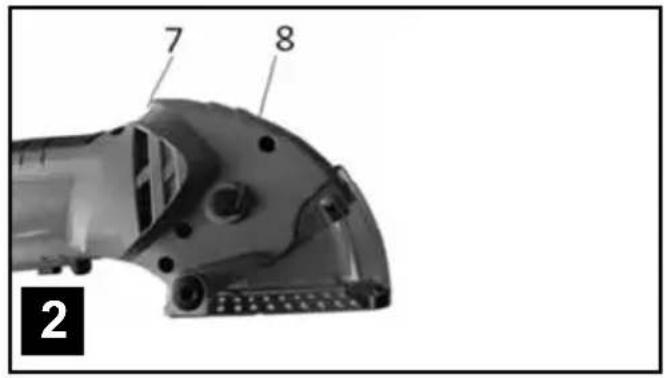
text_image
7 8 2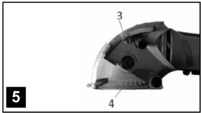
text_image
3 4 5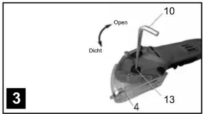
text_image
Open Dicht 10 13 4 3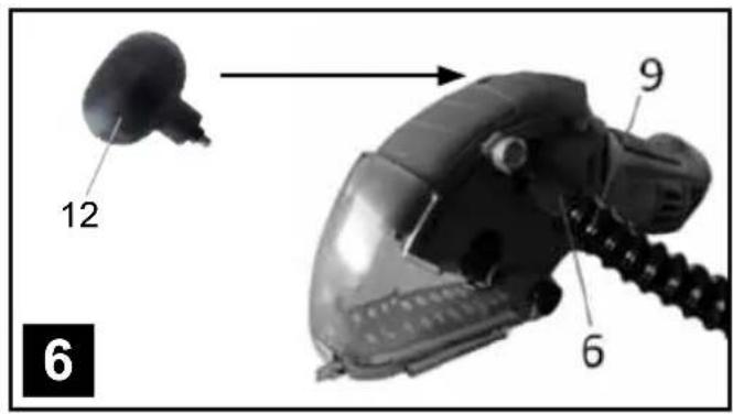
text_image
12 9 6 6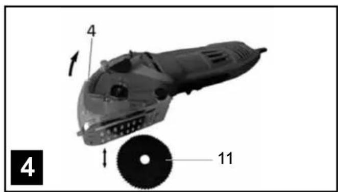
text_image
4 1 11 4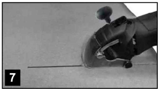
natural_image
Close-up of a robotic arm gripping a cylindrical object, with no visible text or symbols1. VERKLARING VAN DE SYMBOLEN

text_image
Handwritten signature or scribble on a white backgroundnatural_image
3D model of a futuristic vehicle with labeled parts (4, 11) and directional arrows indicating motion or assembly (no text beyond labels)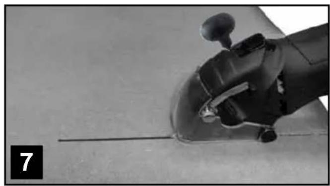
natural_image
Close-up of a robotic arm gripping a cylindrical object, with no visible text or symbols1. EXPLICATION DES SYMBOLES

text_image
Handwritten signature or scribble on a white background, possibly a signature or nameThis product has got a 2 year warranty
Dear Client, if for any reason this product is not working, please ensure you contact our
Client Service Centre. Ensure you have your original receipt of purchase. This warranty covers all defects in workmanship or materials in this Batavia product for a two year period from the date of purchase. The warranty does not cover any malfunction, or defect resulting from misuse, neglect, alteration, or repair.
Other European countries | Customer Services
Monday till Friday from 8 am until 4 pm
Overige landen Europa | Klantenservice