
DVM894 - Multimeter VELLEMAN - Free user manual and instructions
Find the device manual for free DVM894 VELLEMAN in PDF.
User questions about DVM894 VELLEMAN
0 question about this device. Answer the ones you know or ask your own.
Ask a new question about this device
Download the instructions for your Multimeter in PDF format for free! Find your manual DVM894 - VELLEMAN and take your electronic device back in hand. On this page are published all the documents necessary for the use of your device. DVM894 by VELLEMAN.
USER MANUAL DVM894 VELLEMAN
DIGITAL MULTIMETER 3½ DIGITS - 32 RANGES DIGITALE MULTIMETER 3½-DIGITS - 32 BEREIKEN MULTIMÈTRE NUMÉRIQUE 3½-DIGITS - 32 GAMMES MULTÍMETRO DIGITAL DE 3½ - 32 RANGO 3½-STELLIGES MULTIMETER - 32 BEREICHE MULTIMETR CYFROWY LCD 3½ - 32 OPCJE 3½ DMM - 32 NÍVEIS
USER MANUAL 3 GEBRUIKERSHANDLEIDING 17 MODE D'EMPLOI 32 MANUAL DEL USUARIO 47 BEDIENUNGSANLEITUNG 61 INSTRUKCJA OBSŁUGI 76 MANUAL DO UTILIZADOR 92
CE
USER MANUAL
1. Introduction
To all residents of the European Union
Important environmental information about this product
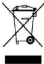
This symbol on the device or the package indicates that disposal of the device after its lifecycle could harm the environment. Do not dispose of the unit (or batteries) as unsorted municipal waste; it should be taken to a specialized company for recycling. This device should be returned to your distributor or to a local recycling service. Respect the local environmental rules.
If in doubt, contact your local waste disposal authorities.
Thank you for choosing Velleman! Please read the manual thoroughly before bringing this device into service. If the device was damaged in transit, do not install or use it and contact your dealer.
Refer to the Velleman® Service and Quality Warranty on the last pages of this manual.
2. Used Symbols
 | This symbol indicates: Read instructions. Not reading the instructions and manual can lead to damage, injury or death. |
 | This symbol indicates: Danger.A hazardous condition or action that may result in injury or death. |
 | This symbol indicates: Risk of danger/damage.Risk of a hazardous condition or action that may result in damage, injury or death. |
 | This symbol indicates: Attention; important information. Ignoring this information can lead to hazardous situations. |
 | AC (Alternating Current) |
 | DC (Direct Current) |
 | Both AC and DC |
 | Double insulation (class 2-protection) |
 | Earth |
 | Fuse |
 | Capacitor |
 | Diode |
 | Continuity |
3. Safety Instructions
 | Read this manual thoroughly. Familiarise yourself with the functions of the device before actually using it. | |
 | Only use the device for its intended purpose. Using the device in an unauthorized way will void the warranty. Damage caused by disregard of certain guidelines in this manual is not covered by the warranty and the dealer will not accept responsibility for any ensuing defects or problems. | |
 | WARNING: To avoid electrical shock always disconnect the test leads prior to opening the housing. To prevent damage or injury, only use batteries and fuses of the same type and ratings as specified in this manual.Remark: Refer to the warning on the back of the meter. | |
 | Keep the device away from children and unauthorised users. | |
 | Protect this device from shocks and abuse. Avoid brute force when operating. | |
 | Avoid cold, heat and large temperature fluctuations. When the unit is moved from a cold to a warm location, leave it switched off until it has reached room temperature. This to avoid condensation and measuring errors. | |
 | This is an installation category CAT III 600V measuring instrument. Never use this equipment in a higher category than indicated. Refer to §4 Overvoltage/installation category. | |
 | Pollution degree 2-device. For indoor use only. Keep this device away from rain, moisture, splashing and dripping liquids. Not for industrial use.Refer to §5 Pollution degree. | |
 | For your safety, use only the test leads supplied with the instrument.Before use, check that they are in good condition. Do not use the meter or test leads if they look damaged. When damaged, replace them with test leads of the same type and with the same specifications. | |
 | Always place your fingers behind the protective edges of the test probes while measuring!Never touch free terminals when the meter is connected to a circuit. | |
 | Use the correct input terminals, function, and range for your measurements. When the range of the value to be measured is unknown, check that the range initially set on the meter is the highest possible. To avoid damages to the instrument, do not exceed the maximum limits of the input values as shown in the technical specifications tables. | |
 | Risk of electric shock during operation. Be very careful when measuring live circuits. Use extreme caution when measuring voltages higher than 60 VDC or 30 VAC rms. | |
DVM894
 | When using the mA terminal: do not measure current in circuits with voltages > 250 V.When using the 10A terminal: do not measure current in circuits with voltages > 500 V. |
 | Disconnect circuit power and discharge all high-voltage capacitors before testing resistance, continuity, capacitance or diodes. For transistor tests, use the included transistor socket. |
 | In TV repair work or when carrying out measurements on power switching circuits, remember that high-amplitude voltage pulses at the test points can damage the meter. Use of a TV filter will attenuate any such pulses. |
 | Do not replace internal parts yourself. Replace damaged or lost accessories by identical ones with the same specifications. Order spare accessories, e.g. test leads, from your dealer. |
 | Switch off the meter and remove test probes prior to replacing the battery or fuses. |
 | All modifications of the device are forbidden for safety reasons. Damage caused by user modifications to the device is not covered by the warranty. |
- If the meter is used near a source of electromagnetic interference, the display may become unstable or may indicate large errors.
- Use the meter only as specified in this manual; otherwise, the protection provided by the meter may be impaired.
- Use extreme caution when working around bare conductors or bus bars.
- Do not operate the meter near explosive gases, vapour, or dust.
- Verify the meter's operation by measuring a known voltage. Do not use the meter if it operates abnormally. Protection may be impaired. When in doubt, have the meter serviced by a qualified technician. Make sure the device cannot be used until it is repaired.
- When making connections, connect the common test lead (black) before connecting the live test lead (red). When disconnecting, disconnect the live test lead (red) before disconnecting the common test lead (black).
- Before changing functions or measuring range, disconnect the test leads from the circuit under test.
- For all DC functions, to avoid the risk of shock due to possible improper readings, verify the presence of any AC voltages first by using the AC function. Then select a DC voltage range equal to or greater than the AC range.
- Use a 9 V battery, properly installed in the meter's battery case, to power the meter.
- Replace the battery as soon as the battery indicator 📋 appears. With a low battery, the meter may produce false readings that can lead to electric shock and personal injury.
- Do not operate the meter with the case (or part of the case) removed.
- Always verify that all connections are reliable and safe.
- Avoid body contact with ground potential (e.g. metallic terminals, output sockets, lead clamp...) while measuring. Make sure to be electrically insulated from ground during measurement.
4. Overvoltage/Installation Category
DMMs are categorized depending on the risk and severity of transient overvoltage that might occur at the point of test. Transients are short-lived bursts of energy induced in a system, e.g. caused by lightning strike on a power line.
The existing categories according EN 61010-1 are:
| CAT I | A CAT I-rated meter is suitable for measurements on protected electronic circuits that are not directly connected to mains power, e.g. electronics circuits, control signals... |
| CAT II | A CAT II-rated meter is suitable for measurements in CAT I environments and mono-phase appliances that are connected to the mains by means of a plug and circuits in a normal domestic environment, provided that the circuit is at least 10 m apart from a CAT III, or 20 m apart from a CAT IV environment. E.g. household appliances, portable tools... |
| CAT III | A CAT III-rated meter is suitable for measurements in CAT I and CAT II environments, as well as for measurements on (fixed) mono- or poly-phased appliances which are at least 10 m apart from a CAT IV environment, and for measurements in or on distribution level equipment (fuse boxes, lighting circuits, electric ovens). |
| CAT IV | A CAT IV-rated meter is suitable for measuring in CAT I, CAT II and CAT III environments as well as on the primary supply level. Note that for all measurements on equipment for which the supply cables run outdoors (either overhead or underground) a CAT IV meter must be used. |
Warning: This device was designed in accordance with EN 61010-1 installation category CAT III 600V. This implies that certain restrictions in use apply that are related to voltages and voltage peaks which can occur within the environment of use. Refer to the table above.
This device is suitable for measurements up to 600 V:
- measurements in/on low-voltage distribution boards (distribution boards behind meter box)
- measurements on (fixed) mono- or poly-phased appliances and circuits except in CAT IV environments (e.g. mains outlets, electric ovens, lighting circuits, bus bars, low-voltage distribution boards and circuit breakers).
This device is NOT suitable for:
• Voltages above 1000 V
- Measurements on distribution equipment and outdoor installations including meter boxes and equipment/circuits outside or remote from the domestic environment e.g. circuits in sheds, garden houses and free-standing garages, or circuits using underground wiring e.g. garden lighting, pool-pump...

THIS DEVICE IS ONLY SUITABLE FOR MEASUREMENTS UP TO 600 V IN CAT III.
5. Pollution Degree
IEC 61010-1 specifies different types of pollution environments, for which different protective measures are necessary to ensure safety. Harsher environments require more protection, and the protection against the pollution which is to be found in a certain environment depends mainly on the insulation and the enclosure properties. The pollution degree rating of the DMM indicates in which environment the device may be used.
| Pollution degree 1 | No pollution or only dry, nonconductive pollution occurs. The pollution has no influence (only to be found in hermetically sealed enclosures). |
| Pollution degree 2 | Only nonconductive pollution occurs. Occasionally, temporary conductivity caused by condensation is to be expected (home and office environments fall under this category). |
| Pollution degree 3 | Conductive pollution occurs, or dry nonconductive pollution occurs that becomes conductive due to condensation that is to be expected (industrial environments and environments exposed to outside air - but not in contact with precipitation). |
| Pollution degree 4 | The pollution generates persistent conductivity caused by conductive dust or by rain or snow (exposed outdoor environments and environments where high humidity levels or high concentrations of fine particles occur). |
Warning: This device was designed in accordance with EN 61010-1 pollution degree 2. This implies that certain restrictions in use apply that are related to pollution which can occur within the environment of use. Refer to the table above.

THIS DEVICE IS ONLY SUITABLE FOR MEASUREMENTS IN POLLUTION DEGREE CLASS 2 ENVIRONMENTS.
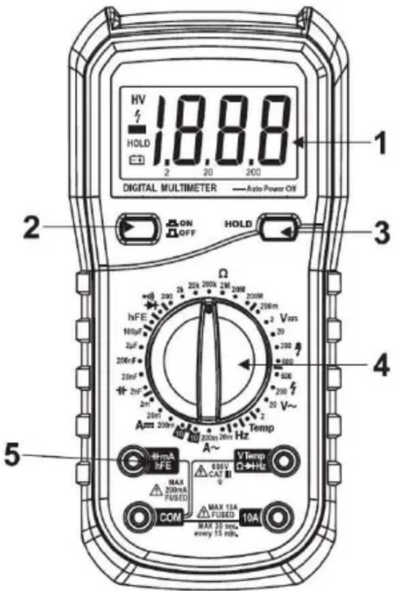
6. Overview
Refer to the illustrations on page 2 of this manual.
| 1 | LCD display: 3 1⁄2 digits, 2000 counts |
| 2 | power button |
| 3 | HOLD: to hold the last reading |
| 4 | rotary switch: to select functions and the desired ranges |
| 5 | input sockets |
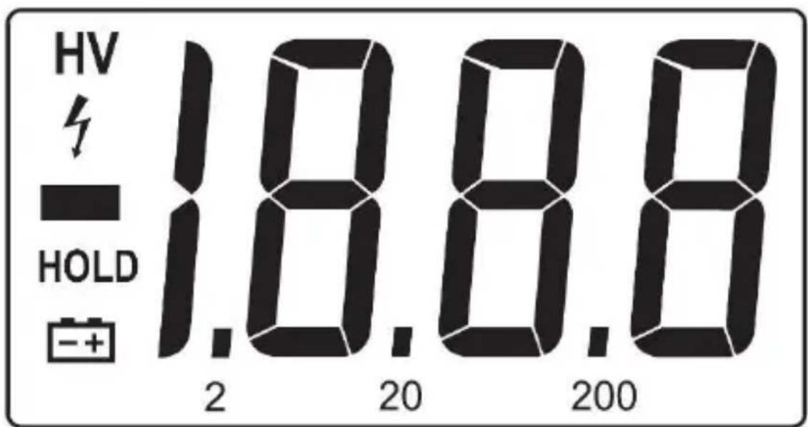
Display
 | low battery | |
 | Warning: To avoid false readings, which can possibly lead to electric shocks or personal injury, replace the battery as soon as the battery indicator appears. | |
| negative input polarity indication | ||
| HV | high-voltage symbol (600 VAC or 600 VDC) | |
| HOLD | data-hold mode | |
Input socket
| COM | common inut terminal |
| V, Ω, HzTEMP | input terminal for all other measurements |
| mA hFE | input terminal for transistor, capacitance, and current measurements |
| 10A | input terminal for currents between 200 mA and 10 A |
7. Use
7.1 Preparation
- Switch on the meter by turning the rotary switch. If the battery voltage is lower than 7 V, the low-battery symbol will appear and the batteries should be replaced.
- The warning symbol next to the input lead shows that the input voltage or current should not exceed the specified value in order to protect the internal circuit from damage.
- Turn the rotary switch to the required function and range to be measured.
- Choose the highest range when the value to be measured is unknown.
- When making connection, connect the common test lead first and then the powered test lead.
- Remove the charged test lead first when disconnecting.
7.2 Readings Hold
- Press HOLD to hold the reading of the current measurements.
- Press HOLD again to release the reading.
7.3 AC/DC Voltage Measurement

USE CAUTION WHEN MEASURING HIGH-VOLTAGE CIRCUITS TO AVOID ELECTRICAL SHOCK AND INJURY. DO NOT TEST VOLTAGES HIGHER THAN 600 V AC/DC.
- Plug the black test lead into the COM jack and the red test lead into the VTempΩ→Hz jack.
- Set the rotary switch to the V≡ position for DC measurement and V ∼ for AC measurement. Select the proper range.
- Connect the test leads to the voltage source or load for measurement.
- Read the value on the main indicator of the LCD. The polarity symbol denotes the polarity of the end connected by the red test lead.
Notes
- At small voltage ranges, unsteady readings will appear before the test leads make contact with the circuit. This is normal since the meter is highly sensitive. When the test leads are connected to the circuit, the tru readings will be shown.
- When 1 appears on the LCD, it means the measurement has exceeded the allowable range. A higher range should be selected.
- When the scale of the value to be measured is unknown, select the highest range first and lower the range accordingly.
7.4 AC/DC Current Measurement

USE CAUTION WHEN MEASURING HIGH-VOLTAGE CIRCUITS TO AVOID ELECTRICAL SHOCK AND INJURY. DO NOT TEST VOLTAGES HIGHER THAN 600 V AC/DC.

TO AVOID ELECTRICAL SHOCK AND INJURY, POWER OFF THE CIRCUIT AND DISCHARGE THE CAPACITORS BEFORE MEASURING CURRENT.
- Plug the black test lead into the COM jack.
- When the current to be measured is under 200 mA, plug the red test lead into the mA jack. When the current to be measured is between 200 mA and 10 A, plug the red test lead into the 10A jack.
- Set the rotary switch to the A≡ position for DC measurement and A ∼ for AC measurement. Select the proper range.
- Connect the test leads to the circuit.
- Read the value on the display.
- The polarity symbol denotes the polarity of the red test lead.
Notes
- When 1 appears on the LCD, it means the measurement has exceeded the allowable range. A higher range should be selected.
- When the scale of the value to be measured is unknown, select the highest range first and lower the range accordingly.
- The warning symbol indicates that the maximum current of the mA jack is 200 mA and the maximum current of the 10A jack is 10 A. At either jack, current exceeding the limit will blow the fuse.
7.5 Resistance Measurement

TO AVOID ELECTRICAL SHOCK AND INJURY, POWER OFF THE CIRCUIT AND DISCHARGE THE CAPACITORS BEFORE MEASURING RESISTANCE.
- Plug the black test lead into the COM jack and the red test lead into the VTempΩHz jack.
- Set the rotary switch to the position and select the proper range.
- Connect the test leads to the ends of the resistor or circuit.
- Read the value on the LCD.
Notes
- When the input is open, 1 is displayed on the LCD to indicate overload. For measuring resistance above 1 MΩ, it may take a few seconds to get a steady reading. This is normal for high-resistance measurement.
7.6 Diode
- Plug the black test lead into the COM jack and the red test lead into the VTempΩHz jack.
- Set the rotary switch to the position.
- Connect the red test lead to the anode and the black test lead to the cathode of the diode for testing.
- Read the value on the LCD.
Notes
- The meter will show the approximate forward voltage drop of the diode.
- When the test leads are reversed or opened, 1 will appear on the LCD.
7.7 Continuity
TO AVOID ELECTRICAL SHOCK AND INJURY, POWER OFF THE CIRCUIT AND DISCHARGE THE CAPACITORS BEFORE MEASURING CONTINUITY.
- Plug the black test lead into the COM jack and the red test lead into the VTempΩHz jack.
- Set the rotary switch to the position.
- Connect the test leads to two ends of the circuit. If resistance of the circuit is less than 50 Ω, the built-in buzzer will sound.
7.8 Capacitance
TO AVOID ELECTRICAL SHOCK AND INJURY, POWER OFF THE CIRCUIT AND DISCHARGE THE CAPACITORS BEFORE MEASURING CAPACITANCE.
- Plug the black test lead into the COM jack and the red test lead into the hFE-mA jack.
- Set the rotary switch to the position and select the proper range.
- Connect the test leads to two ends of the circuit/capacitor and read the value on the LCD.
7.9 Frequency Measurement
- Plug the black test lead into the COM jack and the red test lead into the VTempΩHz jack.
- Set the rotary switch to the Hz position.
- Connect the test leads to two ends of the circuit and read the value on the LCD.
7.10 Temperature

TO AVOID ELECTRICAL SHOCK AND INJURY, DO NOT MEASURE THE SURFACE OF THE OBJECT WITH AN ELECTRICAL POTENTIAL HIGHER THAN 60 VDC/24 VAC.
- Plug the multi-function socket with the IN end in the VTempΩ→Hz jack and the COM end in the COM jack.
- Insert the K-type thermocouple into the multi-function socket with the correct polarity.
- Set the rotary switch to the TEMP position.
- Use the thermocouple to measure the temperature of the surface of the test object.
- Read the value on the LCD.
7.11 Transistor Gain

TO AVOID ELECTRICAL SHOCK AND INJURY, DO NOT TEST WITH VOLTAGES HIGHER THAN 250 V AC/DC.
- Plug the multi-function socket with the IN end in the hFE-1(mA jack and the COM end in the COM jack.
- Set the rotary switch to the hFE position and select the proper range.
- Determine if the transistor to be tested is either an NPN or PNP type, then insert the three pins of the transistor into the corresponding holes of the multi-function socket.
- Read the approximate transistor gain on the LCD.
8. Cleaning and Maintenance
Instructions for Safe Maintenance
- Meter calibration, maintenance, repair, and other operations can only be performed by technicians who fully understand the meter and electrical shock hazards. Do not attempt to repair or service the meter unless you are qualified to do so and have the relevant calibration, performance test and service information.
- When performing meter maintenance, only use specified and approved replacement parts.
- Before opening the meter, disconnect all power supplies and make sure that you have no static electricity to avoid damaging the meter components.
- Be aware that there may be dangerous voltages remaining in some capacitors in the meter even after powering off.
DVM894

TO AVOID ELECTRICAL SHOCK, ALWAYS DISCONNECT THE TEST LEADS BEFORE OPENING THE HOUSING. TO PREVENT FIRE HAZARDS, INSTALL FUSES WITH THE EXACT SAME SPECIFICATIONS. TO AVOID ELECTRICAL SHOCK AND/OR DAMAGE TO THE INSTRUMENT, DO NOT GET WATER INSIDE THE HOUSING. REFER TO THE WARNING ON THE BACK OF THE METER.
DO NOT REPLACE INTERNAL PARTS YOURSELF. REPLACE DAMAGED OR LOST ACCESSORIES BY IDENTICAL ONES WITH THE SAME SPECIFICATIONS. ORDER SPARE ACCESSORIES, E.G. TEST LEADS, FROM YOUR DEALER.
SWITCH OFF THE METER AND REMOVE TEST LEADS PRIOR TO REPLACING THE BATTERY OR FUSES.
General Maintenance
Wipe the device regularly with a moist, lint-free cloth and a small amount of detergent. Do not use alcohol, solvents or abrasive products.
Dirty or wet input sockets may affect the readings. To clean the input sockets:
- Switch off the meter.
- Remove the test probes from the circuit under test. Remove all test leads from the input sockets.
- Gently remove any dirt that may be in the sockets.
- Soak a new cotton bud with a cleaning and oiling agent and clean the sockets.
- Make sure the sockets are perfectly clean and dry before using the meter again.
Battery Replacement

LOW/BAD BATTERIES CAN PRODUCE FALSE READINGS, WHICH CAN POSSIBLY LEAD TO ELECTRIC SHOCKS OR PERSONAL INJURY. THEREFORE, YOU MUST REPLACE THE BATTERY AS SOON AS THE BATTERY INDICATOR APPEARS. USE ONLY BATTERIES OF THE SPECIFIED TYPE AND RATING (9 V).
TO AVOID SHOCK OR PERSONAL INJURY, BEFORE OPENING THE BATTERY COVER, ALWAYS TURN OFF THE METER AND DISCONNECT THE TEST LEADS.
DO NOT PUNCTURE BATTERIES OR THROW THEM IN FIRE AS THEY MAY EXPLODE. DO NOT ATTEMPT TO RECHARGE NON-RECHARGEABLE BATTERIES (ALKALINE). DISPOSE OF BATTERIES IN ACCORDANCE WITH LOCAL REGULATIONS. KEEP BATTERIES AWAY FROM CHILDREN.
- Switch off the meter.
- Remove the test probes from the circuit under test. Remove the test leads from the input sockets.
- Unscrew the battery cover at the back of the meter.
- Replace the battery (9 V). Do not use rechargeable batteries and respect the polarity.
- Close the battery cover and tighten the screw.
Fuse Replacement

USE ONLY FUSES OF THE SPECIFIED TYPE, RATINGS, AND SPEED (F250MA/250 V, F10A/500 V CERAMIC). THE FUSE RARELY NEEDS TO BE REPLACED AND A BLOWN FUSE IS ALMOST ALWAYS CAUSED BY A HUMAN ERROR. TO AVOID SHOCK OR PERSONAL INJURY, BEFORE OPENING THE HOUSING, ALWAYS TURN OFF THE METER AND DISCONNECT THE TEST LEADS.
- Switch off the meter.
- Remove the test probes from the circuit under test. Remove the test leads from the input sockets.
- Remove the battery.
- Remove the protective cover, unscrew the screws at the back of the meter and gently open the housing. The fuses are located at the bottom of the PCB.
- Replace the blown fuse with a fuse of the same type and rating.
- Close the housing and tighten the screws. Put the protective cover back.
- Place the battery back and close the battery cover.
Storage
- Remove the batteries from the device if it will not be used for a long time. Old batteries can begin to leak and damage the device.
- Do not store the device in a high temperature or high humidity environment.
Fuse Replacement

REPLACE THE TEST LEADS WITH IDENTICAL OR COMPATIBLE LEADS. LEAD SPECIFICATIONS: 1000 V, 10 A.
- Replace worn leads.
9. Technical Specifications
DC Voltage
| range | resolution | accuracy |
| 200 mV | 0.1 mV | ± (0.5 % of readings + 2 digits) |
| 2 V | 1 mV | |
| 20 V | 10 mV | |
| 200 V | 100 mV | |
| 600 V | 1 V | ± (0.8 % of readings + 2 digits) |
- Max. input voltage: 250 VDC at 200 mV range, 600 VDC elsewhere.
- Input impedance: 10 MΩ.
DVM894
Notes
- At small voltage ranges, unsteady readings will appear before the test leads make contact with the circuit. This is normal since the meter is highly sensitive. When the test leads are connected to the circuit, the tru readings will be shown.
AC Voltage
| range | resolution | accuracy |
| 2 V | 1 mV | ± (0.8 % of readings + 3 digits) |
| 20 V | 10 mV | |
| 200 V | 100mV | |
| 600 V | 1 V | ± (1.2 % of readings + 2 digits) |
- Max. input voltage: 250 VDC at 200 mV range, 600 VDC elsewhere.
- Input impedance: 10 MΩ.
• Frequency response: 200 Hz at 600 V range, 40-400 Hz elsewhere. - Response: average (RMS of sine wave).
Notes
- At small voltage ranges, unsteady readings will appear before the test leads make contact with the circuit. This is normal since the meter is highly sensitive. When the test leads are connected to the circuit, the tru readings will be shown.
DC Current
| range | resolution | accuracy |
| 2 mA | 1 μA | ± (0.8 % of readings + 1 digit) |
| 20 mA | 10 μA | |
| 200 mA | 0.1 mA | ± (1.5 % of readings + 1 digit) |
| 10 A | 10 mA | ± (2.0 % of readings + 5 digits) |
• Overload protection:
- mA ranges: resettable fuse F1, 400 mA/600 V (quick acting).
- 10 A range: F2, 10 A/600 V fuse (quick acting).
• Max. input current:
○ mA jack (mA range): 200 mA.
○ 10 A range: 10 A.
AC Current
| range | resolution | accuracy |
| 20 mA | 10 μA | ± (1.0 % of readings + 5 digits) |
| 200 mA | 0.1mA | ± (1.8 % of readings + 5 digits) |
| 10 A | 10 mA | ± (3.0 % of readings + 7 digits) |
• Overload protection:
o mA ranges: resettable fuse F1, 400 mA/600 V (quick acting).
- 10 A range: F2, 10 A/600 V fuse (quick acting).
• Max. input current:
○ mA jack (mA range): 200 mA.
○ 10 A range: 10 A.
• Frequency response: 40-400 Hz.
- Response: average (RMS of sine wave).
DVM894
Resistance
| range | resolution | accuracy |
| 200 Ω | 0.1 Ω | ± (0.8 % of readings + 3 digits) |
| 2 kΩ | 1 Ω | ± (0.8 % of readings + 2 digits) |
| 20 kΩ | 10 Ω | |
| 200 kΩ | 100 Ω | |
| 2 MΩ | 1 kΩ | |
| 20 MΩ | 10 kΩ | ± (1.0 % of readings + 2 digits) |
| 200 MΩ | 100 kΩ | ± (6.0 % of readings + 10 digits) |
• Overload protection: 250 V AC/DC.
- Open circuit voltage: DC 2.8 V.
Diode
| range | resolution | function |
 | 1 mV | approximate forward voltage of the diode |
Continuity Test
| function | ||
 | built-in buzzer will sound if resistance is lower than 50 Ω | |
Frequency
| range | resolution | accuracy |
| 20 kHz | 10 Hz | ± (2.0 % of readings + 5 digits) |
Capacitance
| range | resolution | accuracy |
| 2 nF | 1 pF | ± (4.0 % of readings + 3 digits) |
| 20 nF | 10 pF | |
| 200 nF | 0.1 nF | |
| 2 μF | 1 nF | |
| 100 μF | 100 nF | ± (6.0 % of readings + 10 digits) |
Temperature
| range | resolution | accuracy |
| -20°C to 0°C | 1°C | ± (5.0 % of readings + 4 digits) |
| 1°C to 400°C | ± (2.0 % of readings + 3 digits) | |
| 401°C to 1000°C | ± (2.0 % of readings + 5 digits) |
Transistor
| range | description | test condition |
| hFE | hFE approximation (0-1000) | base current 10 μA Vce is about 2.8 VDC |
General Technical Specifications
| over range indication | yes, 1 |
| continuity buzzer | yes |
| transistor test | yes |
| diode test | yes |
| low-battery indication | yes |
| maximum display | 1999 |
| LCD display size | 31 x 61 mm |
| ranging mode | manual |
| data hold | yes |
| backlight | no |
| dimensions | 195 x 89 x 51 mm |
| weight (with battery) | ± 366 g |
| power supply | 1 x 9 V battery (6F22) |
| packing | blister |
| accessories | user manual/test leads/holster/battery/K-type thermocouple (250°C)/multifunctional socket |
| auto power-off | yes |
Use this device with original accessories only. Velleman nv cannot be held responsible in the event of damage or injury resulting from (incorrect) use of this device. For more info concerning this product and the latest version of this manual, please visit our website www.velleman.eu.
The information in this manual is subject to change without prior notice.
© COPYRIGHT NOTICE
The copyright to this manual is owned by Velleman nv. All worldwide rights reserved.
No part of this manual may be copied, reproduced, translated or reduced to any electronic medium or otherwise without the prior written consent of the copyright holder.
GEBRUIKERSHANDLEIDING
1. Inleiding
Velleman® Service and Quality Warranty
Since its foundation in 1972, Velleman® acquired extensive experience in the electronics world and currently distributes its products in over 85 countries.
All our products fulfil strict quality requirements and legal stipulations in the EU. In order to ensure the quality, our products regularly go through an extra quality check, both by an internal quality department and by specialized external organisations. If, all precautionary measures notwithstanding, problems should occur, please make appeal to our warranty (see guarantee conditions).
General Warranty Conditions Concerning Consumer Products (for EU):
- All consumer products are subject to a 24-month warranty on production flaws and defective material as from the original date of purchase.
- Velleman® can decide to replace an article with an equivalent article, or to refund the retail value totally or partially when the complaint is valid and a free repair or replacement of the article is impossible, or if the expenses are out of proportion.
You will be delivered a replacing article or a refund at the value of 100% of the purchase price in case of a flaw occurred in the first year after the date of purchase and delivery, or a replacing article at 50% of the purchase price or a refund at the value of 50% of the retail value in case of a flaw occurred in the second year after the date of purchase and delivery.
- Not covered by warranty:
- all direct or indirect damage caused after delivery to the article (e.g. by oxidation, shocks, falls, dust, dirt, humidity...), and by the article, as well as its contents (e.g. data loss), compensation for loss of profits;
- consumable goods, parts or accessories that are subject to an aging process during normal use, such as batteries (rechargeable, non-rechargeable, built-in or replaceable), lamps, rubber parts, drive belts... (unlimited list);
- flaws resulting from fire, water damage, lightning, accident, natural disaster, etc....;
- flaws caused deliberately, negligently or resulting from improper handling, negligent maintenance, abusive use or use contrary to the manufacturer's instructions;
- damage caused by a commercial, professional or collective use of the article (the warranty validity will be reduced to six (6) months when the article is used professionally);
- damage resulting from an inappropriate packing and shipping of the article;
- all damage caused by modification, repair or alteration performed by a third party without written permission by Velleman®.
- Articles to be repaired must be delivered to your Velleman® dealer, solidly packed (preferably in the original packaging), and be completed with the original receipt of purchase and a clear flaw description.
- Hint: In order to save on cost and time, please reread the manual and check if the flaw is caused by obvious causes prior to presenting the article for repair. Note that returning a non-defective article can also involve handling costs.
- Repairs occurring after warranty expiration are subject to shipping costs.
- The above conditions are without prejudice to all commercial warranties.