
DVM4100 - Multimeter VELLEMAN - Free user manual and instructions
Find the device manual for free DVM4100 VELLEMAN in PDF.


| Product Type | Digital Multimeter |
| Brand | Velleman |
| Model | DVM4100 |
| Dimensions (approx.) | 180 x 85 x 35 mm |
| Weight (approx.) | 350 g |
| Power Supply | 9V battery (type 6F22) |
| Display | LCD screen 3 ½ digits (1999 counts) |
| Maximum voltage (DC) | 1000 V |
| Maximum voltage (AC) | 750 V |
| Maximum current (DC) | 10 A |
| Maximum resistance | 20 MΩ |
| Continuity test | Yes (threshold < 30 Ω) |
| Diode test | Yes |
| Capacitance (optional) | Not provided (check manual) |
| Frequency (optional) | Not provided (check manual) |
| Safety category | CAT II 1000 V / CAT III 600 V |
| Operation | Measurement of voltage, current, resistance, continuity, diode |
| Maintenance and cleaning | Clean with a soft, dry cloth. Do not use solvents. |
| Safety | Follow safety instructions: do not measure voltages above the category, use appropriate test leads. |
| Spare parts / Repairability | Batteries and fuses replaceable. For any other repair, contact an authorized service center. |
Frequently Asked Questions - DVM4100 VELLEMAN
User questions about DVM4100 VELLEMAN
0 question about this device. Answer the ones you know or ask your own.
Ask a new question about this device
Download the instructions for your Multimeter in PDF format for free! Find your manual DVM4100 - VELLEMAN and take your electronic device back in hand. On this page are published all the documents necessary for the use of your device. DVM4100 by VELLEMAN.
USER MANUAL DVM4100 VELLEMAN
DVM4100 : with usb interface
met usb-interface
avec interface usb
con interfaz usb
natural_image
Interior view of a green electronic device casing with visible circuitry and wiring (no text or symbols)User manual
1. Introduction
To all residents of the European Union
Important environmental information about this product

This symbol on the device or the package indicates that disposal of the device after its lifecycle could harm the environment. Do not dispose of the unit (or batteries) as unsorted municipal waste; it should be taken to a specialized company for recycling.
This device should be returned to your distributor or to a local recycling service. Respect the local environmental rules.
If in doubt, contact your local waste disposal authorities.
Thank you for choosing Velleman! Please read the manual thoroughly before bringing this device into service. If the device was damaged in transit, don't install or use it and contact your dealer.
Refer to the Velleman® Service and Quality Warranty on the last pages of this manual.
2. Used symbols
 | This symbol indicates: Read instructionsNot reading the instructions and manual can lead to damage, injury or death. |
 | This symbol indicates: DangerA hazardous condition or action that may result in injury or death |
 | This symbol indicates: Risk of danger/ damageRisk of a hazardous condition or action that may result in damage, injury or death |
 | This symbol indicates: Attention; important information gnoring this information can lead to hazardous situations. |
 | AC (Alternating Current) |
| DC (Direct Current) | |
 | Bot h AC and DC |
| Double insulation (class II-protect ion) | |
 | Earth |
| Fuse | |
 | Capacit or |
| Diode | |
 | Continuity |
| Backlight |
3. Safety instructions
 | Follow the inst ruct ions below to guarantee a safe use of the meter and all its functionalities. | |
 | During use of the meter, respect all directives concerning protection against electroshocks and misuse. Never exceed the indicated limits. | |
 | WARNING:For safety reasons, please read the manual.Remark: this warning is also found on the back of the meter (top part). | |
 | WARNING: To avoid electrical shock always disconnect the test leads prior to opening the housing. To prevent damage or injury, only use batteries and fuses with the same ratings as specified in this manual.Remark: refer to the warning on the back of the meter. | |
 | Avoid cold, heat and large temperature fluctuations. When unit is moved from a cold to a warm location, leave it switched off until it has reached room temperature. This to avoid condensation and measuring errors. | |
 | Protect this device from shocks and abuse. Avoid brute force when operating. | |
 | Pollution degree 2-device. For indoor use only. Keep this device away from rain, moisture, splashing and dripping liquids. Not for industrial use.Refer to §5 Pollution degree. | |
 | Keep the device away from children and unauthorised users. | |
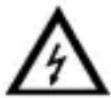 | Risk of electric shock during operation. Be very careful when measuring live circuits. Use extreme caution when measuring voltages higher than 60Vdc or 30Vac rms. | |
 | Do not replace internal parts yourself. Replace damaged or lost accessories by identical ones with the same specifications. Order spare accessories e.g. test probes at your dealer. | |
 | This is an installation category CAT IV 600V / CAT III 1000V measuring instrument. Never use this equipment in a higher category than indicated. Refer to §4 Overvoltage / installation category. | |
 | Read this manual thoroughly. Familiarise yourself with the functions of the device before actually using it. | |
 | All modifications of the device are forbidden for safety reasons. Damage caused by user modifications to the devic e is not covered by the warranty | |
 | Only use the device for its intended purpose. Using the device in an unauthorized way will void the warranty. Damage caused by disregard certain guidelines in this manual is not covered by the warranty and the dealer will not accept responsibility for any ensuing defects or problems. | |
 | Make sure the meter is in the appropriate measuring range before connecting it to a test circuit. | |
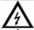 | Do not measure circuits that may contain voltages > 1000V (DC or rms AC) | |
 | Do not measure current in circuits with voltages > 1000V | |
 | Do not conduct resistance, diode- or continuity measurements on live circuits. | |
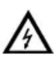 | Before each use, make sure the test probes are in good condition. Always place your fingers behind the protective edges of the test probes while measuring!Nevertouch free terminals when the meter is connected to a circuit. | |
 | Switch off the meter and remove test probes prior to replacing the batt or fuses. | |
 | When carrying out measurements on a TV set or switching power circuits, always be aware that high amplitude voltage pulses at the test points might damage the meter. | |
4. Overvoltage/ installation category
DMMs are categorized depending on the risk and severity of transient overvoltage that might occur at the point of test. Transients are short-lived bursts of energy induced in a system, e.g. caused by lightning strike on a power line.
The existing categories according EN 61010-1 are:
| CAT I | A CAT I-rated meter is suitable for measurements on protected electronic circuits that are not directly connected to mains power, e.g. electronics circuits, control signals... |
| CAT II | A CAT II-rated meter is suitable for measurements in CAT I-environments and mono-phase appliances that are connected to the mains by means of a plug and circuits in a normal domestic environment, provided that the circuit is at least 10m apart from a CAT III- or 20m apart from a CAT IV-environment. E.g. household appliances, portable tools... |
| CAT III | A CAT III-rated meter is suitable for measurements in CAT I- and CAT II-environments, as well as for measurements on (fixed) mono- or poly-phased appliances which are at least 10m apart from of a CAT IV-environment, and for measurements in or on distribution level equipment (low-voltage distribution boards, lighting circuits, electric ovens). |
| CAT IV | A CAT IV-rated meter is suitable for measuring in CAT I-, CAT II- and CAT III-environments as well as on the primary supply level. Note that for all measurements on equipment for which the supply cables run outdoors (either overhead or underground) a CAT IV meter must be used. |
Warning:
This device was designed in accordance with EN 61010-1 installation category CAT IV 600V / CAT III 1000V. This implies that certain restrictions in use apply that are related to voltages and voltage peaks which can occur within the environment of use. Refer to the table above.
This device is suitable for measurements up to 1000V:
- Protected electronic circuits that are not directly connected to mains power, e.g. electronics circuits, control signals, c circuits behind isolating transformer...
- circuits that are directly connected to mains power, but limited to:
o measurements on mono-phase appliances that are connected to the mains by means of a plug
○ mono-phase appliances and circuits directly connected to the mains in a normal domestic environment, provided that the circuit is at least 10m apart from a CAT IV-environment. E.g. household appliances, portable tools, light circuits at more than 10m from a distribution board ...
- measurements in/on low-voltage distribution boards (distribution boards behind meter box)
- measurements on (fixed) mono- or poly-phased appliances and circuits except in CAT IV-environments (e.g. mains outlets, electric ovens, lighting circuits, bus bars, low-voltage distribution boards and circuit breakers).
This device is suitable for measurements up to 600V:
- Measurements on distribution equipment and outdoor installations including meter boxes and equipment/circuits outside or remote from the domestic environment e.g. circuits in sheds, garden houses and free-standing garages, or circuits using underground wiring e.g. garden lighting, pool-pump...
This device is NOT suitable for:
• Voltages above 1000V
- Currents above 10A

This device is only suitable for measurements up to 600V in
5. Pollution degree
IEC 61010-1 specifies different types of pollution environments, for which different protective measures are necessary to ensure safety. Harsher environments require more protection, and the protection against the pollution which is to be found in a certain environment depends mainly on the insulation and the enclosure properties. The pollution degree rating of the DVM indicates in which environment the device may be used.
| Pollution degree 1 | No pollution or only dry, nonconductive pollution occurs. The pollution has no influence. (only to be found in hermetically sealed enclosures) |
| Pollution degree 2 | Only nonconductive pollution occurs. Occasionally, temporary conductivity caused by condensation is to be expected.(home and offi environments fall under this category) |
| Pollution degree 3 | Conductive pollution occurs, or dry nonconductive pollution occurs that becomes conductive due to condensation that is to be expected. (industrial environments and environments exposed to outside air - but not in contact with precipitation) |
| Pollution degree 4 | The pollution generates persistent conductivity caused by conductive dust or by rain or snow. (exposed outdoor environments and environments where high humidity levels or high concentrations of fine part ic les occur) |
Warning:
This device was designed in accordance with EN 61010-1 pollution degree 2. This implies that certain restrictions in use apply that are related to pollution which can occur within the environment of use. Refer to the table above.

This device is only suitable for measurements in Pollution degree class 2 environments.
6. Description
Refer to the illustrations on pages 2 and 3 of this manual.
6.1 Multi-meter
| 1 | LCD | 7 | COM terminal |
| 2 | funct ion keys | 8 | PC link connector (DVM4100 only) |
| 3 | rotary switch | 9 | not used |
| 4 | VΩ→+Hz terminal | 10 | foldable stand |
| 5 | μAm A terminal | 11 | batt e ry compart ment |
| 6 | 10A terminal | ||
6.2 Display
| No. | Symbol | Meaning |
| A |  | indicates negative readings |
| B | indicator for AC voltage or current | |
| C | indicator for DC voltage or current | |
| D AUTO | the meter is in the Auto range mode (automatically selects the range with the best resolution) | |
| E | PC-LINK | the meter is in the data transmission mode (DVM4100 only) |
| F | H | the meter is in Data Hold mode. |
| G | REL | the meter is in Relative Measurement mode. |
| H | MAX | max imum dat a is displayed |
| I | MIN | mini mu m data is displayed |
| J | [y3CK] | low battery indication |
| K | 01) | the meter is in Continuity Check mode. |
| L |  | the meter is in Diode Test mode. |
| M | % °C °FKMΩ HznμmF AV | Measurement units |
6.3 Function keys
| key | function Meaning | |
| SELECT | Ω → + o)) | Switch between resistance measurement, diode test and continuity test. |
| mA μA | Switch between DC and AC current. | |
| power off | Press and hold while switching on to disable sleep mode. | |
 | all | Press to enter/exit Data Hold mode. Press and hold for ±2s to switch h the bac klight on/off. |
| RANGE | V~, V= , Ω, mA, μA | Press to enter manual ranging mode and to scroll through the different ranges. Press and hold for ±2s to return to auto-ranging. |
| REL △ | all except Hz/ Duty | Press to enter/exit relative measurement mode. |
| Hz % | V~, A, mA, μA | Press to start frequency counter, press again to enter Duty Cycle (load factor). Press again to exit frequency counter.Press and hold while switching on the meter to start data transmission (DVM4100 only). |
| MAX MIN | all except Hz/ Duty and -||- | Press to measure maximum m value, press again to measure mini mu m v a lues.Press and hold for ±2s to return to normal measuring mode. |
6.4 Mode description
DATA HOLD mode
- In Data Hold mode, the display is not longer updated.
- Press the HOLD button to enter Data Hold mode. H is shown on the display [F].
- When Data Hold mode is enabled in auto range mode, the meter switches to manual ranging mode.
- To exit Data Hold mode, press the RANGE or HOLD button
Manual / Auto range mode
- The meter has both manual and auto range options.
- In the auto range mode, the meter selects the best range for the input detected. This allows you to switch test points without having to reset the range. When the meter is in the auto range mode, AUTO is displayed [D].
- In the manual ranging mode, the range must be selected manually. This allows the user to override auto range and lock the meter in a specific range.
- The meter defaults to auto range mode for measurement functions that have more than one range.
- To enter and exit the manual range mode press the RANGE button. Press successively to scroll through the available ranges.
- To exit the manual ranging mode, press and hold down RANGE key for two seconds. The meter returns to the auto range mode and AUTO is displayed.
Sleep mode
- The Meter enters the "sleep mode" and blanks the display if the meter is on but not used for 30 minutes.
- Press the HOLD button or rotate the rotary switch to wake the meter up.
- To disable Sleep mode, hold down the SELECT key while turning the meter on.
Relative measurement mode
- Relative measurement mode is available during all functions except frequency.
- To enter and exit the relative measurement mode, start the measurement.
- Press REL △ key to store the measured value and activate the relative measurement mode. The difference between the reference value and subsequent reading is displayed. REL is shown on the display [G].
- Press REL △ key for more than 2 seconds to return the meter to normal operation.
6.5 PC Link (model DVM4100 only)
• PC Link is only compatible with Windows XP, Vista and Windows 7 32 & 64 bit.
- The DVM4100 has a serial data output function.
- Before continuing the necessary USB driver and software must be installed on the PC. Insert the included CD ROM into a suitable PC. Locate and open the file README.pdf for the installation procedure (English only). Follow the instructions on the screen
Notes:
- First install the PC-link software followed by the USB driver, than restart the PC.
- log in on the PC as administrator. For Vista/Windows 7 systems, disable the UAC (User Account Control) (via Control Panel – System and Security – Action Center – User Account Control settings -> Never notify.)
- Connect the meter to a USB port of a PC using the included data cable.
- Press and hold the Hz % button while turn on the meter, the meter enter PC-Link mode. T the symbol “PC-LINK” will appear on the LCD [E] and the serial data output function is active.
Notes:
- It is not possible to enter PC LINK during measurement; the meter must be switched off first.
- To disable the auto power off function, simultaneously hold down the SELECT and Hz% button while turning the meter on.
- Run the PC-LINK software, click the SET menu. Select the System Set. Then select the proper COM port in the Serial Port Select. To determine the COM port, go to Device Manager:
- Right-click the My Computer icon on the Windows desktop, and then click Properties.
- Click the Hardware tab and then click Device Manager.
-
Scroll through the list of installed devices and locate the Ports (Com and LPT) entry. Click the plus (+) next to this entry to view the installed ports, If no errors occurred, the “Prolific USB-to-Serial COM Port (COM x)” will appear, COM x is the port, with x = a specific number.
-
Select the default sampling rate or set a desired sampling rate.
- Now press the Start in the PC-LINK SOFT to measure and view the real-time data or graph in the software interface.
- To disable the serial data output function, switch the meter OFF.
- More information about the PC-LINK SOFT can be found in the help-file of the software.
7. Operating instructions

Risk of electric shock during operation. Be very careful when measuring live circuits.

Before measuring, always make sure the meter and/or test probes are damaged and verify the connections, selected function and range.
- Never exceed the limit value for protection. This limit value is listed separately in the specifications for each range of measurement.
- Do not touch unused terminals when the meter is linked to a circuit which is being tested.
- Only use the meter in the indicated overvoltage/installation category. Never measure voltages that might exceed the indicated category values.
- When a measuring range is unknown, always select the highest possible range and lower to the appropriate range.
- Disconnect the test leads from the tested circuit before rotating the range selector in order to change functions.
- When carrying out measurements on a TV set or switching power circuits, always remember that high amplitude voltage pulses at the test points might damage the meter.
- Always be careful when working with voltages above 60Vdc or 30Vac rms. Keep your fingers behind the probe barriers at all times during measurement.
- Do not measure current in circuits with voltages > 1000V.
- Never perform resistance, diode or continuity measurements on live circuits. Make sure all capacitors in the circuit are depleted.
7.1 Voltage measurements

Do not measure circuits where voltages > 600V CAT IV or > 1000V CAT III may reside.

Always be careful when working with voltages above 60Vdc or 30Vac rms. Keep your fingers behind the probe barriers at all times during measurement. Do not touch unused terminals when the meter is linked to a circuit which is being tested.
- Connect the red test lead to the "VΩ → +Hz ↓" jack and the black lead to the "COM" jack.
- Set the rotary switch to V = for DC measurements or to V \~ for AC measurements.
- Press the RANGE button to manually select the range.
- Connect the test probes to the source being measured.
- The measured value appears on the LCD display.
Notes:
- For DC-measurements, when a negative polarity is present at the red test lead, the indicated value is preceded by a “-” sign.
- When measuring DC offset of an AC voltage, measure the AC voltage first and select a range for the DC offset equal to or higher than the AC range to increase accuracy.
7.2 Resistance measurements

Do not perform resistance measurements on live circuits.
- Connect the red test lead to the "VΩ ➕ +Hz ↓" jack and the black lead to the "COM" jack.
- Set the rotary switch to "Ω". When necessary, press the SELECT button until MΩ is shown on the display.
- Press the RANGE button to manually select the range.
- Connect the test probes to the source being measured.
- The measured value appears on the LCD display.
- Notes:
- Never perform resistance measurements on a live circuit and make sure all capacitors are completely depleted.
To increase accuracy when measuring low resistance values, first hold the tips of the measuring probes together to determine the resistance value of the test leads. Subtract this value from the measured value of the circuit. - For resistance measurements above 10MΩ the meter needs a few seconds to stabilize the read-out.
- Should the measured resistance exceed the current range or in case of an open circuit, the display will show "OL".
7.3 Continuity measurements
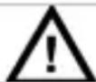
Do not perform continuity measurements on live circuits.
- Connect the red test lead to the "VΩ → +Hz ↓" jack and the black lead to the "COM" jack.
- Set the rotary switch to
- Press the SELECT button to select continuity test
- Connect the test probes to the source being measured.
- When the measured resistance is less than 40 a continuous beep is produced and the resistance value is showed on the display. Should the measured resistance exceed the current range or in case of an open circuit, the display will show “OL”.
Nota: Never perform continuity measurements on a live circuit and make sure all capacitors are completely depleted.
7.4 Diode measurements

Do not perform diode measurements on live circuits.
- Connect the red test lead to the "VΩ ➕ +Hz ↓" jack and the black lead to the "COM" jack.
- Set the rotary switch to
- Press the SELECT button to select diode test
- Connect the red test probe to the anode of the diode and the black test probe to the cat hode.
- The meter shows the forward voltage drop of the diode. When the diode is connected with a reversed polarity, the display shows "OL".
Notes:
- Never perform diode measurements on a live circuit and make sure all capacitors are completely depleted.
○ Measuring diodes that are part of a circuit might produce faulty results. Consider unmounting from the circuit.
7.5
Capacitance measurements

Do not perform capacitance measurements on live circuits.
- Connect the red test lead to the "VΩ ➕ Hz ♪" jack and the black lead to the "COM" jac k.
- Set the rotary switch to
- Press the RANGE button to manually select the range.
- Connect the test probes to the capacitor and read its value from the display.
Notes:
- It takes a few seconds before the meter shows the result. This is normal behavior (e.g. 300.0 F range >30s ).
To increase accuracy when measuring low capacitance values (<4nF), first hold the tips of the measuring probes together to determine the capacitance value of the test leads. Subtract this value from the measured value of the circuit. - Never perform capacitance measurements on a live circuit and make sure all capacitors are completely depleted.
7.6 Frequency measurements

Do not perform frequency measurements in circuits with voltages > 1000V.

Always be careful when working with voltages above 60Vdc or 30Vac rm. Keep your fingers behind the probe barriers at all times during measurement. Do not touch unused terminals when the meter is linked to circuit which is being tested.
- Connect the red test lead to the "VΩ → +Hz ↓" jack and the black lead to the "COM" jac k.
- Set the rotary switch to Hz.
- Press the RANGE button to manually select the range.
- Connect the test probes to the circuit and read the measured value from the LCD.
Notes:
- The frequency can also be measured during AC voltage/current measurement.
Start the measurement and press the HZ % button to measure the frequency or duty cycle. - Use a shielded cable for measuring small signals in a noisy environment.
7.7 Temperature measurements

Do not touch any live parts with the temperature measuring probe
- Set the rotary switch to the ^ range. When no temperature measuring probe is connected, the current environmental temperature is displayed.
- Place the adaptor socket between the "VΩ ➡ +Hz ↓" and the "COM" jack (align "+" with "VΩ ➡ +Hz ↓").
- Plug the thermocouple (type K) into the adaptor socket (align “+” with “+”).
- Hold the tip of the temperature probe against the object under test.
- Read the temperature on the LCD.
7.8 Current Measurements

Do not measure current in circuits with voltages > 1000V

Current measuring jack μA/mA max. 600mA.
For currents up to 10A use the 10A jac k.

Always be careful when working with voltages above 60Vdc or 30Vac rm. Keep your fingers behind the probe barriers at all times during measurement.
- For measurements up to 600mA: connect the red test lead to the "μAmA" jack and the black lead to the "COM" jack.
- For measurements up to 10A: connect the red test lead to the "10A" jack and the black lead to the "COM" jack.
- Set the rotary switch to the A range for measurements up to 600 A (only when test probe is connected to the AmA jack).
- Set the rotary switch to the mA range for measurements up to 600mA (only when test probe is connected to the μAmA jack).
- Set the rotary switch to the A range for measurements up to 10A (only when test probe is connected to the 10A jack).
- Press the SELECT button to select DC current (DCA) or AC current (ACA) mode.
- Connect the test probes in series with the circuit.
- Read the measured value from the display.
Notes:
o for DC-current measurements, when a negative polarity is present at the red test lead, the indicated value is preceded by a “-” sign.
- The AmA-range is protected against over current with a F630mA 1000V fuse, the 10A-range is protected against over current with a F10A 1000V fuse.
8. Maintenance

Do not replace internal parts yourself. Replace damaged or lost accessories by identical ones with the same specifications. Order spare accessories e test probes at your dealer.
a. General maintenance
Wipe the device regularly with a moist, lint-free cloth. Do not use alcohol or solvent s.
b. Fuse Replacement

Switch off the multi-meter, disconnect the test leads from the test points and remove the test leads from the measuring jacks before replacing t batteries or fuses.
Refer to the illustration on pages 3 of this manual.
- Remove the 4 screws at the back (indicated with ▶ in the illustration) and gently open the meter.
- Remove the screw that holds the PCB in place (indicated with ▶ in the illustration) and gently lift the PCB.
- Remove the fuse from the fuse holder and replace it with a new fuse of the same type and with the same specifications (F630mA/1000V - ∅10.3x38mm, F10A/1000V - ∅10.3x38mm).
- Close the meter meticulously.
c. Battery Replacement

To avoid false readings, which could lead to possible electric shocks or personal injury, replace the battery as soon as the battery indicator appears.

Switch off the multi-meter, disconnect the test leads from the test points and remove the test leads from the measuring jacks before replacing the batteries or fuses.
Refer to the illustration on pages 3 of this manual.
- Remove the 2 screws at the back of the meter (indicated with b) in the illustration) and gently open the battery compartment.
- Replace the battery (9V 6LF22). Do not use rechargeable batteries. Insert following the right polarity.
- Close the battery compartment and reseat the screws.

9. Technische specificaties
This device is not calibrated when purchased!
Regulations concerning environment of use:
- Use this meter only for measurements in CATI, CATII, CAT III (<1000V) and CAT IV (<600V) environments (see §4)
- Use this meter only in a pollution degree 2 environment (see §5)
Ideal working conditions include:
• Temperature: 18 to 28°C (64°F to 82°F)
• relative humidity: max. 75%
• altitude: max. 2000m (6560ft)
9.1. General
| Max. Voltage | 600V CAT IV, 1000V CAT III |
| Display | 3 °/° digit LCD, 2 to 3 samples/sec. |
| Fuse Protection | μA/mA-range: 630mA/1000V (Ø10.3x38mm)10A-range: 10A/1000V (Ø10.3x38mm) |
| Temperature coefficient | 0.1x(specified accuracy)/°C (<18°C or >28°C) |
| Power Supply | 9V alkaline battery 6LR61 |
| Ranging Method | manual/ automatic |
| Polarity Indication | " - " is displayed |
| Overrange Indication | "OL" is displayed automatically |
| Battery-Low Indication | " " is displayed |
| Operating Temperature | 0°C to 40°C (32~122°F) (<80% RH, <10°C non condensing) |
| Storage Temperature | -10°C to 60°C (14~140°F) (<70%RH, battery removed) |
| Dimensions | 190x90x40mm |
| Weight | ±500g (incl. battery) |
9.2. DC Voltage
| Range | Resolution | Accuracy |
| 600mV | 100μV | ±(0.5% of rdg + 5 digits) |
| 6V | 1mV | ±(0.8% of rdg + 5 digits) |
| 60V | 10mV | |
| 600V | 100mV | |
| 1000V | 1V | ±(1.0% of rdg + 2 digits) |
Input Impedance: >10MΩ for all ranges
9.3. AC Voltage
| Range | Resolution | Accuracy |
| 600mV | 100μV | ±(1.0% of rdg + 5 digits) |
| 6V | 1mV | |
| 60V | 10mV | |
| 600V | 100mV | ±(1.5% of rdg + 2 digits) |
| 1000V | 1V |
Input Impedance: >10MΩ for all ranges
Frequency Range: 40 to 400Hz
Overload protection: 1000Vdc or ac rms.
9.4. DC Current
| Range | Resolution | Accuracy |
| 600μA | 0.1μA | ±(1.5% of rdg + 3 digits) |
| 6mA | 1μA | |
| 60mA | 10μA | |
| 600mA | 0.1mA | |
| 6A | 1mA | ±(1.5% of rdg + 5 digits) |
| 10A | 10mA |
When measuring currents > 6A, max. 15s continuous measurement followed by a 15 minutes break between 2 measurements.
Overload Protection: 600mA range F0.63A/1000V–10A range fuse F10A/1000V
9.5. Resistance
| Range | Resolution | Accuracy |
| 600Ω | 0.1Ω | ±(0.5% of rdg + 3 digits) |
| 6kΩ | 1Ω | ±(0.5% of rdg + 2 digits) |
| 60kΩ | 10Ω | |
| 600kΩ | 100Ω | |
| 6MΩ | 1kΩ | |
| 60MΩ | 10kΩ | ±(1.5% of rdg + 5 digits) |
Note: in range 600 , short circuit test leads to determine lead resistance, than subtract this value from the measured value.
9.6. Diode and audible continuity test
| Range | parameters |
| [2x6T] | Built-in buzzer sounds if resistance < 30Ω |
 | Forward test current(DC): ± 1mAReversed test voltage: ± 1.5Vdc |
9.7. Capacitance
| Range | Resolution | Accuracy |
| 60nF | 10pF | <10nF: ±(5.0% of (rdg - 50 digits) + 20 digits)>10nF: ±(3.0% of rdg + 10 digits) |
| 600nF | 100pF | ±(5.0% of rdg + 10 digits) |
| 6μF | 1nF | |
| 60μF | 10nF | |
| 300μF | 100nF |
9.8. Temperature
| Range | Resolution | Accuracy |
| -55°C ~ 0°C | 0.1°C | ± (5.0% of rdg + 4°C) |
| 1°C ~ 400°C | ± (1.0% of rdg + 3°C) | |
| 401°C ~ 1,000°C | 1°C | ± (2.0% of rdg) |
Note: thermocouple errors not included
9.9. Frequency
| Range Resolution | Accuracy | ||
| Logic(1Hz~1MHz) | Linear(6Hz~10KHz) | ||
| 99.99Hz | 0.01Hz | ± (0.1% of rdg + 3 digits) | ± (0.05% of rdg + 8 digits) |
| 999.9Hz | 0.1Hz | ||
| 9.999kHz | 1Hz | ||
| 99.99kHz | 10Hz | N.A. | |
| 999.99kHz | 100Hz | ||
Use this device with original accessories only. Velleman nv cannot be held responsible in the event of damage or injury resulted from (incorrect) use of this device. For more info concerning this product and the latest version of this user manual, please visit our website www.velleman.eu. The information in this manual is subject to change without prior notice.
© COPYRI GH T NO TICE
This manual is copyrighted. The copyright to this manual is owned by Velleman nv. All world wide rights reserved. No part of this manual may be copied, reproduced, translated or reduced to any electronic medium or otherwise without the prior written consent of the copyright holder.
GEBRUI KERSHANDLEI DING
1. Inleiding
9.2. Tension continue
| Plage | Résolution | Précision |
| 600mV | 100μV | ±(0.5% de l'affichage + 5 digits) |
| 6V | 1mV | ±(0.8% de l'affichage + 5 digits) |
| 60V | 10mV | |
| 600V | 100mV | |
| 1000V | 1V | ±(1.0% de l'affichage +2 digits) |
© D ROITS D 'A UTE UR
Velleman® Service and Quality Warranty
Since its foundation in 1972, Velleman® acquired extensive experience in the electronics world and currently distributes its products in over 85 countries.
All our products fulfil strict quality requirements and legal stipulations in the EU. In order to ensure the quality, our products regularly go through an extra quality check, both by an internal quality department and by specialized external organisations. If, all precautionary measures notwithstanding, problems should occur, please make appeal to our warranty (see guarantee conditions).
General Warranty Conditions Concerning Consumer Products (for EU):
- All consumer products are subject to a 24-month warranty on production flaws and defective material as from the original date of purchase.
- Velleman® can decide to replace an article with an equivalent article, or to refund the retail value totally or partially when the complaint is valid and a free repair or replacement of the article is impossible, or if the expenses are out of proportion.
You will be delivered a replacing article or a refund at the value of 100% of the purchase price in case of a flaw occurred in the first year after the date of purchase and delivery, or a replacing article at 50% of the purchase price or a refund at the value of 50% of the retail value in case of a flaw occurred in the second year after the date of purchase and delivery.
- Not covered by warranty:
- all direct or indirect damage caused after delivery to the article (e.g. by oxidation, shocks, falls, dust, dirt, humidity...), and by the article, as well as its contents (e.g. data loss), compensation for loss of profits;
- consumable goods, parts or accessories that are subject to an aging process during normal use, such as batteries (rechargeable, non-rechargeable, built-in or replaceable), lamps, rubber parts, drive belts... (unlimited list);
- flaws resulting from fire, water damage, lightning, accident, natural disaster, etc....;
- flaws caused deliberately, negligently or resulting from improper handling, negligent maintenance, abusive use or use contrary to the manufacturer's instructions;
- damage caused by a commercial, professional or collective use of the article (the warranty validity will be reduced to six (6) months when the article is used professionally);
- damage resulting from an inappropriate packing and shipping of the article;
- all damage caused by modification, repair or alteration performed by a third party without written permission by Velleman®.
- Articles to be repaired must be delivered to your Velleman® dealer, solidly packed (preferably in the original packaging), and be completed with the original receipt of purchase and a clear flaw description.
- Hint: In order to save on cost and time, please reread the manual and check if the flaw is caused by obvious causes prior to presenting the article for repair. Note that returning a non-defective article can also involve handling costs.
- Repairs occurring after warranty expiration are subject to shipping costs.
- The above conditions are without prejudice to all commercial warranties.
The above enumeration is subject to modification according to the article (see article's manual).
NL
Imported by Velleman nv
Legen Heirweg 33, 9890 Gavere, Belgium
www.velleman.eu


- User manual
- Introduction
- To all residents of the European Union
- If in doubt, contact your local waste disposal authorities.
- Used symbols
- Safety instructions
- Overvoltage/ installation category
- Warning:
- This device is suitable for measurements up to 1000V:
- This device is suitable for measurements up to 600V:
- This device is NOT suitable for:
- Pollution degree
- Description
- Multi-meter
- Display
- Function keys
- Mode description
- DATA HOLD mode
- Manual / Auto range mode
- Sleep mode
- Relative measurement mode
- PC Link (model DVM4100 only)
- Notes:
- Operating instructions
- Voltage measurements
- Resistance measurements
- Do not perform resistance measurements on live circuits.
- Continuity measurements
- Do not perform continuity measurements on live circuits.
- Diode measurements
- Do not perform diode measurements on live circuits.
- 7.5
- Capacitance measurements
- Do not perform capacitance measurements on live circuits.
- Frequency measurements
- Do not perform frequency measurements in circuits with voltages > 1000V.
- Temperature measurements
- Do not touch any live parts with the temperature measuring probe
- Current Measurements
- Do not measure current in circuits with voltages > 1000V
- Maintenance
- a. General maintenance
- b. Fuse Replacement
- c. Battery Replacement
- Technische specificaties
- Resistance
- Diode and audible continuity test
- Capacitance
- Temperature
- Frequency
- GEBRUI KERSHANDLEI DING
- Inleiding
- Tension continue
- Velleman® Service and Quality Warranty
- General Warranty Conditions Concerning Consumer Products (for EU):
- - Not covered by warranty:
- NL
Brand : VELLEMAN
Model : DVM4100
Category : Multimeter