RW 500 - Rowing Machine Christopeit - Free user manual and instructions
Find the device manual for free RW 500 Christopeit in PDF.
| Product type | Rowing machine |
| Brand | Christopeit |
| Model | RW 500 |
| Dimensions (unfolded) | 175 x 47 x 76 cm (L x W x H) |
| Dimensions (folded) | 90 x 47 x 133 cm (L x W x H) |
| Device weight | 25 kg |
| Maximum user weight | 120 kg |
| Resistance system | Magnetic braking, 10 adjustable levels |
| Digital display | Time, strokes, strokes/min, calories, total strokes, heart rate |
| Pulse measurement | Manual sensors on handlebar (separate display) |
| Power supply | 2x AAA micro batteries (for heart rate display) |
| Frame material | Sturdy steel |
| Seat | Comfortable, equipped with ball-bearing rollers |
| Resistance adjustment range | Levels 1 to 10 |
| Maintenance | Clean with a damp cloth; oil knurled screw and threads every 100 hours |
| Storage | Fold vertically, store in a dry place, remove batteries if unused for >4 weeks |
| Safety | TÜV-GS certified, standards EN ISO 20957-1:2013 + EN 957-7:1998 H/C; private domestic use only |
| Warranty / Repairability | Spare parts available via www.christopeit-service.de; tools included |
| General information | Indoor use; do not use after a heavy meal; consult a doctor before training |
Frequently Asked Questions - RW 500 Christopeit
User questions about RW 500 Christopeit
0 question about this device. Answer the ones you know or ask your own.
Ask a new question about this device
Download the instructions for your Rowing Machine in PDF format for free! Find your manual RW 500 - Christopeit and take your electronic device back in hand. On this page are published all the documents necessary for the use of your device. RW 500 by Christopeit.
USER MANUAL RW 500 Christopeit
natural_image
Person using a rowing machine on a stationary platform (no visible text or symbols)D
text_image
Technical diagram of a mechanical assembly with numbered components for identificationtext_image
Technical diagram of a mechanical device with numbered parts for identificationSchritt 4:
text_image
Technical diagram of a stationary exercise machine with numbered components and labeled partsSchritt 5:
text_image
Technical diagram of a stationary exercise machine with numbered components for identificationSchritt 6:
text_image
Technical diagram of a stationary exercise machine with numbered components and motion arrows indicating rotation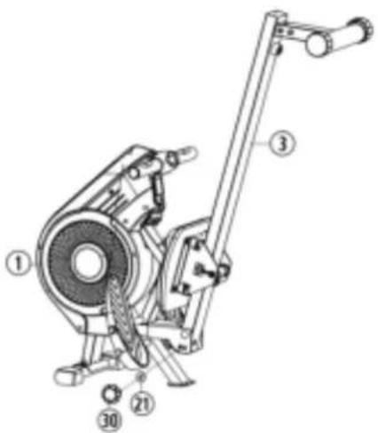
text_image
Technical diagram of a mechanical device with numbered components labeled ①, ②, ③, and ④.Schritt 7:
Kontrolle
natural_image
Line drawing of a stationary exercise machine with levers and legs (no text or symbols)Computeranleitung
natural_image
Person using an olive oil rink on a wooden table (no visible text or symbols)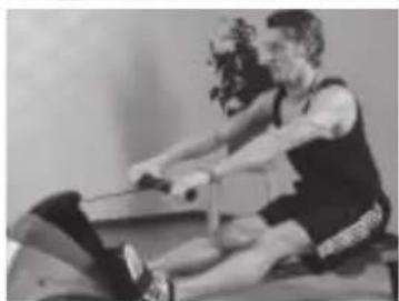
natural_image
Black-and-white photo of a person performing a rowing exercise on a mat (no visible text or symbols)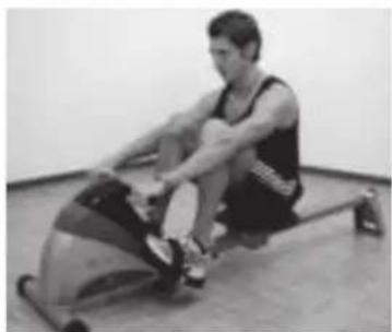
natural_image
Person using an equestrian machine in a gym (no visible text or symbols)line
| X-axis | Maximalpuls (220-After) Maximum pulse rate (200+age) | 90% des Maximalpulses 90% of the maximum pulse rate | 85% des Maximalpulses 80% of the maximum pulse rate | 70% des Maximalpulses 70% of the maximum pulse rate | |---|---|---|---|---| | 20 | 200 | 195 | 180 | 170 | | 25 | 195 | 190 | 175 | 165 | | 30 | 190 | 185 | 171 | 161 | | 35 | 185 | 180 | 166 | 157 | | 40 | 180 | 175 | 162 | 153 | | 45 | 175 | 170 | 157 | 148 | | 50 | 170 | 165 | 153 | 144 | | 55 | 165 | 160 | 148 | 140 | | 60 | 160 | 155 | 144 | 136 | | 65 | 155 | 150 | 139 | 131 | | 70 | 150 | 145 | 135 | 127 | | 20 | 140 | 138 | - | - | | 25 | - | - | - | - | | 30 | - | - | - | - | | 35 | - | - | - | - | | 40 | - | - | - | - | | 45 | - | - | - | - | | 50 | - | - | - | - | | 55 | - | - | - | - | | 60 | - | - | - | - | | 65 | - | - | - | - | | 70 | - | - | - | - | The chart displays a single data series with four distinct lines representing different pulse rate thresholds. The x-axis ranges from '20' to '70', and the y-axis represents numerical values ranging from '100' to '220'. The legend indicates that each line corresponds to a specific pulse rate threshold. The data points are annotated with their respective numerical values at each point. The chart is saved as a PNG file named 'maximalpuls'.Berechnungsformeln: Maximalpuls = 220 - Alter
90% des Maximalpuls = (220 - Alter) x 0,9
85% des Maximalpuls = (220 - Alter) x 0,85
70% des Maximalpuls = (220 - Alter) x 0,7
natural_image
Simple line drawing of a person in a kneeling pose, no text or symbols present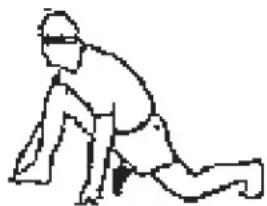
natural_image
Line drawing of a person in a kneeling or stretching pose (no text or symbols)- Important Recommendations and Safety Information Page 10
- Assembly Instructions With Exploded Diagrams Page 11 - 12
- Computer instructions Page 13
- Operating and exercising instructions Page 13
- Cleaning, Storage, Checks, Troubleshooting, Page 14
- Training Instructions, Warm up exercises (Warm Up) Page 15
- Parts List Page 16 - 17
- Summary of Parts Page 42 - 43
Dear customer,
We congratulate you on your purchase of this home training sports unit and hope that we will have a great deal of pleasure with it. Please take heed of the enclosed notes and instructions and follow them closely concerning assembly and use.
Please do not hesitate to contact us at any time if you should have any questions.
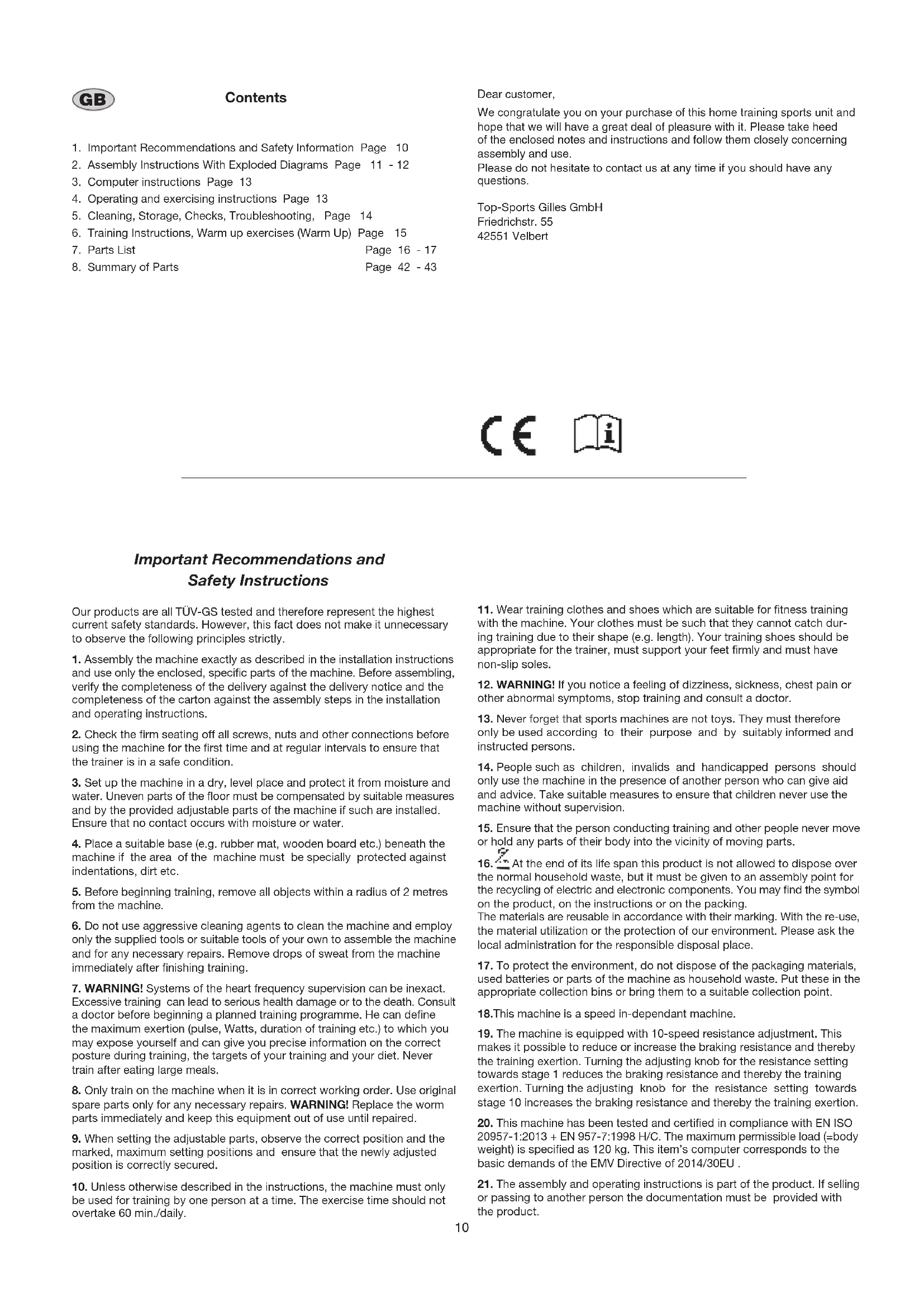
Important Recommendations and Safety Instructions
Our products are all TÜV-GS tested and therefore represent the highest current safety standards. However, this fact does not make it unnecessary to observe the following principles strictly.
- Assembly the machine exactly as described in the installation instructions and use only the enclosed, specific parts of the machine. Before assembling, verify the completeness of the delivery against the delivery notice and the completeness of the carton against the assembly steps in the installation and operating instructions.
- Check the firm seating off all screws, nuts and other connections before using the machine for the first time and at regular intervals to ensure that the trainer is in a safe condition.
- Set up the machine in a dry, level place and protect it from moisture and water. Uneven parts of the floor must be compensated by suitable measures and by the provided adjustable parts of the machine if such are installed. Ensure that no contact occurs with moisture or water.
- Place a suitable base (e.g. rubber mat, wooden board etc.) beneath the machine if the area of the machine must be specially protected against indentations, dirt etc.
- Before beginning training, remove all objects within a radius of 2 metres from the machine.
- Do not use aggressive cleaning agents to clean the machine and employ only the supplied tools or suitable tools of your own to assemble the machine and for any necessary repairs. Remove drops of sweat from the machine immediately after finishing training.
- WARNING! Systems of the heart frequency supervision can be inexact. Excessive training can lead to serious health damage or to the death. Consult a doctor before beginning a planned training programme. He can define the maximum exertion (pulse, Watts, duration of training etc.) to which you may expose yourself and can give you precise information on the correct posture during training, the targets of your training and your diet. Never train after eating large meals.
- Only train on the machine when it is in correct working order. Use original spare parts only for any necessary repairs. WARNING! Replace the worm parts immediately and keep this equipment out of use until repaired.
- When setting the adjustable parts, observe the correct position and the marked, maximum setting positions and ensure that the newly adjusted position is correctly secured.
-
Unless otherwise described in the instructions, the machine must only be used for training by one person at a time. The exercise time should not overtake 60 min./daily.
-
Wear training clothes and shoes which are suitable for fitness training with the machine. Your clothes must be such that they cannot catch during training due to their shape (e.g. length). Your training shoes should be appropriate for the trainer, must support your feet firmly and must have non-slip soles.
- WARNING! If you notice a feeling of dizziness, sickness, chest pain or other abnormal symptoms, stop training and consult a doctor.
- Never forget that sports machines are not toys. They must therefore only be used according to their purpose and by suitably informed and instructed persons.
- People such as children, invalids and handicapped persons should only use the machine in the presence of another person who can give aid and advice. Take suitable measures to ensure that children never use the machine without supervision.
- Ensure that the person conducting training and other people never move or hold any parts of their body into the vicinity of moving parts.
- At the end of its life span this product is not allowed to dispose over the normal household waste, but it must be given to an assembly point for the recycling of electric and electronic components. You may find the symbol on the product, on the instructions or on the packing.
The materials are reusable in accordance with their marking. With the re-use, the material utilization or the protection of our environment. Please ask the local administration for the responsible disposal place. - To protect the environment, do not dispose of the packaging materials, used batteries or parts of the machine as household waste. Put these in the appropriate collection bins or bring them to a suitable collection point.
- This machine is a speed in-dependant machine.
- The machine is equipped with 10-speed resistance adjustment. This makes it possible to reduce or increase the braking resistance and thereby the training exertion. Turning the adjusting knob for the resistance setting towards stage 1 reduces the braking resistance and thereby the training exertion. Turning the adjusting knob for the resistance setting towards stage 10 increases the braking resistance and thereby the training exertion.
- This machine has been tested and certified in compliance with EN ISO 20957-1:2013 + EN 957-7:1998 H/C. The maximum permissible load (=body weight) is specified as 120 kg. This item's computer corresponds to the basic demands of the EMV Directive of 2014/30EU.
- The assembly and operating instructions is part of the product. If selling or passing to another person the documentation must be provided with the product.
Assembly Instructions
Remove all the separate parts from the packaging, lay them on the floor and check that all are there on the basis of the packing list in these instructions for assembly and use. Please note that a number of parts have been connected directly to the main frame and preassembled. In addition, there are several other individual parts that have been attached to separate units. This will make it easier and quicker for you to assemble the equipment. Assembly time: 25 min.
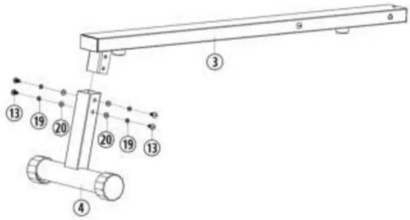
Step 1:
Attach the rear foot (4) at seat slide (3).
- Put the rear foot (4) into the holder at seat frame (3) and screw it tightly by using 4 screws M8x16 (13), washers (20) and spring washers (19).
text_image
Technical diagram of a mechanical assembly with numbered components and labeled partsStep 2:
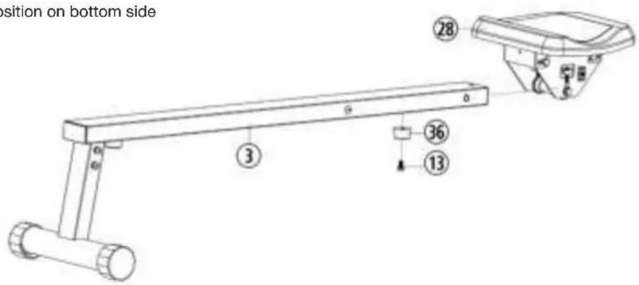
Attach the seat (28) at seat slide (3).
- Remove the cushion pad (36) and screw (13) from seat rail (3).
- Push the seat frame (3) through the seat slide (28) as showed, so that 4 pulleys can roll onto the top side and 2 pulleys can roll onto the bottom side of seat frame (3).
- Fix the cushion pad (36) at appropriate position on bottom side of seat frame (28).
text_image
position on bottom side ③ ②8 ③6 ⑬Step 3:
Attach the Front Foot (2) at main frame (1).
- Place the front foot (2) into the holder in front of the main frame (1) and screw it tightly by using 2 carriage bolts M8x45 (9), washers (20), spring washers (19) and cap nuts (15).
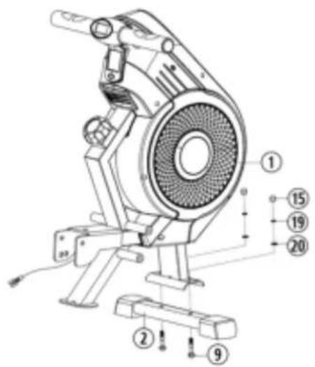
text_image
Technical diagram of a mechanical device with numbered parts for identificationStep 4: Attach the seat frame (3) at main frame (1).
- Place the seat frame (3) against the main frame (1) and connect the sensor cable (41) with connection cable (42).
- Place the seat frame (3) into the holder of main frame (1), so that the holes pattern and screw the seat frame (3) at main frame (1) loosely by using screw M10x105 (11), washer (22) and nut (18). (The seat frame (3) should be fold up easily.)
- Secure the seat frame (3) during training through screw in the star grip screw (30) with washer (21).
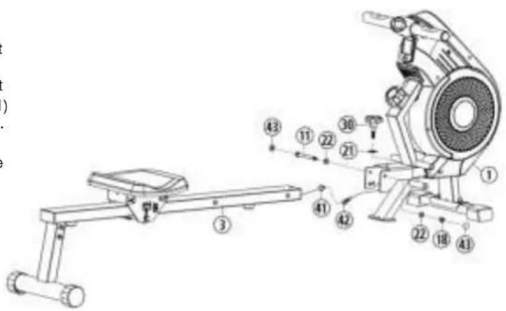
text_image
Technical diagram of a stationary exercise machine with numbered components and labeled partsStep 5: Attach the pedals (37) at main frame (1).
- Put a pedal (37) on screw (10) and tighten the pedals (37) at main frame (1) into appropriate position. Screw a screw (10) in main frame (1) into appropriate position.
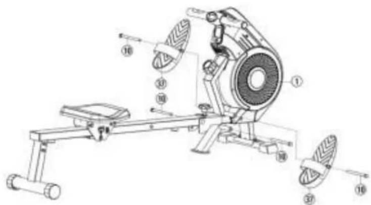
text_image
Technical diagram of a stationary exercise machine with numbered components for identificationStep 6: How to fold up.
- To storage the item, screw out the star grip screw (30) with washer (21) and fold up the Seat frame (3) of item into vertically position. Secure this position with star grip screw (30) and washer (21) into the appropriate position at side of main frame (1).
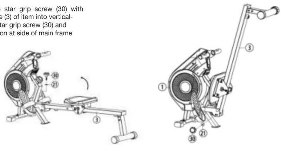
text_image
star grip screw (30) with e (3) of item into vertical- tar grip screw (30) and on at side of main frame ① ③ ②1 ③0 ②1 ③0Step 7: Checks
- Check the correct installation and function of all screwed and plug connections. Installation is thereby complete.
- When everything is in order, familiarise yourself with the machine at a low resistance setting and make your individual adjustments.
Note:
Please keep the tool set and the instructions in a safe place as these may be required for repairs or spare parts orders becoming necessary later.
natural_image
Line drawing of a stationary exercise machine with lever and seat (no text or symbols)Computer instructions
The supplied computer allows the most convenient training. Every value relevant to training is displayed in a corresponding window. From the beginning of the training session, the required time, beats / minute, rower beats, the approximate caloric consumption and the beats Total are displayed. All values are counted from zero upwards.
The computer is switched on by briefly pressing the key or simply by beginning training. The computer begins to register and display all values. The strokes per minute is indicated on the upper display. All other values are indicated on the lower display.
To stop the computer, just stop training. The computer stops all measurements and retains the last attained values. The last attained values in the functions TIME, ROWER BEATS, CALORIES are stored and training can continue with these values when training is resumed.
The computer switches of automatically approx. 4 minutes after training is stopped. All values attained until that time are stored and are displayed again when training is resumed. It is then possible to continue training from these values.
Displays:
1. „Zeit“ display:
The currently required time is displayed in minutes and seconds.
The values last attained by this function are stored.
The current rowing beats are displayed. The values last attained by this function are stored
3. "Schläge/Minute" (beats per minute) display:
The current speed in beats per minute is displayed. The values most recently reached can not be saved in this function, as described above. (Max. display limit is 199 beats per minute)
The current status of the consumed calories (Kcal) is displayed. The values last attained by this function are stored.
The current rowing beats of all trainings sessions are displayed. The values last attained by this function are stored
6. „SCAN“ function:
If this function is selected, the current values of all functions are displayed successively in a constant sequence approx. every 5 seconds.
1. Key:
Pressing this key once briefly makes it possible to change from one function to another. The currently selected function is indicated by an icon in the respective window.
If the key is held longer (approx. 3 seconds), all last attained values are deleted with the exception of the values in the "Schläge-Total" display.
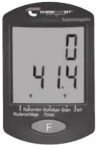
text_image
DARIS-SIT Kaksten Schlage Rutzenstige 4 1.4 0 0 FPulse-Display:
Shows actually heart rate data. The pulse display has 2 batteries inside (Battery type 2x Micro "AAA").
The housing can be opened by screws, to replace the batteries.
Operating and exercising instructions
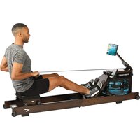
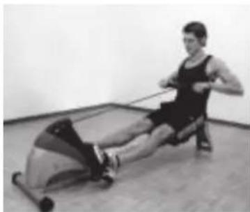
Exercise 1
a) Begin this exercise with your legs straight, knees together and the upper part of your body upright.
b) Bend forward without bending your knees, grip the handle bar and pull back until the upper part of your body is upright again.
Important: The oar levers should be pulled back with the arms (and not with the body) until your hands have reached your body.
c) Bring the handle bar back to the starting position again.
d) Rest for a moment and then carry out the exercise again, repeating it quietly and continuously.
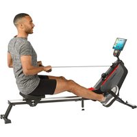
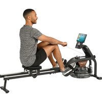
Exercise 2
a) Begin this exercise sitting upright with the seat as far forward as possible and your knees bent.
b) Push back with the legs keeping your knees together and at the same time pulling the handle bar towards you.
c) Continue pulling until your legs are straight and your hands have reached your body.
d) Relax your arms and legs and let the seat slide forward until you have reached the start position (a) again and then repeat the exercise again.
natural_image
Person using a rowing machine in a gym (no visible text or symbols)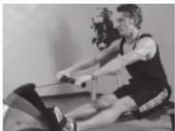
natural_image
Black-and-white photo of a man performing a rowing exercise on a machine (no visible text or symbols)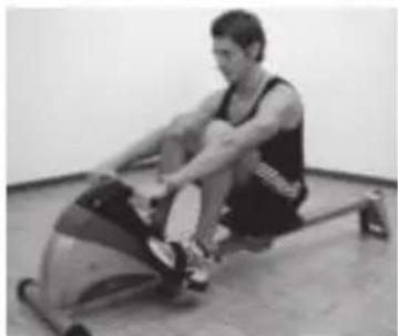
natural_image
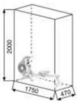
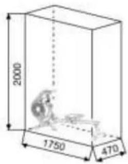
Person performing a row exercise on an outdoor stationary bike (no visible text or symbols)Training area in mm (for home trainer and user)
Free area in mm (Training area and security area (rotating 60cm))
text_image
2000 1750 470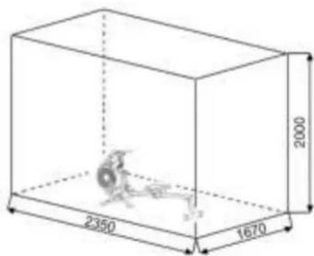
text_image
2350 1670 2000Cleaning, Checks and Storage of the home bike:
1. Cleaning
Use only a less wet cloth for cleaning.
Caution: Never use benzene, thinner or other aggressive cleaning agents for surface cleaning as this damage caused.
The device is only for private home use and for use suitable indoors. Keep the unit clean and moisture from the device.
2. Storage
Remove the batteries from the computer while intending the unit for more than 4 weeks not to use. Fold up the seat frame until it is locked. Choose a dry storage in-house and spray some oil to the thread of the handlebar bolt and on the thread of the quick release for fold up function. Cover the bike to protect it from being discolor by any sunlight and dirty through dust.
3. Checks
We recommend every 50 hours to review the screw connections for tightness, which were prepared in the assembly. Every 100 operating hours, you should spray some oil at the thread of the handlebar bolts and to the thread of quick release for fold up function.
Troubleshooting
If you cannot solve the problem with the following information, please contact the authorized service center.
| Problem Possible Cause Solution | ||
| Computer has no value at Display if you press any key. | No Batteries insert or batteries empty | Check the position of batteries at battery compartment or replace batteries. |
| Computer is not counting data and do not switch on after start cycling. | Sensor impulse missing base on not well plugged connection | Check the plug connections at computer and under the fold up constrcution. |
| Computer is not counting data and do not switch on after start cycling. | Sensor impulse missing base on not correct position of sensor. | Check the distance between magnet and sensor. The magnet which is positioned at seat slide should have only less than < 5mm distance against the sensor position. |
Training instructions
You must consider the following factors in determining the amount of training effort required in order to attain tangible physical and health benefits:
1. Intensity:
The level of physical exertion in training must exceed the level of normal exertion without reaching the point of breathlessness and / or exhaustion. A suitable guideline for effective training can be taken from the pulse rate. During training this should rise to the region of between 70% to 85% of the maximum pulse rate (see the table and formular for determination and calculation of this).
During the first weeks, the pulse rate should remain at the lower end of this region, at around 70% of the maximum pulse rate. In the course of the following weeks and months, the pulse rate should be slowly raised to the upper limit of 85% of the maximum pulse rate. The better the physical condition of the person doing the exercise, the more the level of training should be encreased to remain in the region of between 70% to 85% of the maximum pulse rate. This should be done by lengthening the time for the training and / or encreasing the level of difficulty.
If the pulse rate is not shown on the computer display or if for safety reasons you wish to check your pulse rate, which could have been displayed wrongly due to error in use, etc., you can do the following:
a. Pulse rate measurement in the conventional way (feeling the pulse at the wrist, for example, and counting the number of beats in one minute).
b. Pulse rate measurement with a suitable specialised device (available from dealers specialising in health-related equipment).
2.Frequency
Most experts recommend a combination of health-conscious nutrition, which must be determined on the basis of your training goal, and physical training three times a week. A normal adult must train twice a week to maintain his current level of condition. At least three training sessions a week are required to improve one's condition and reduce one's weight. Of course the ideal frequency of training is five sessions a week.
3. Planning the training
Each training session should consist of three phases: the warm-up phase, the training phase, and the cool-down phase. The body temperature and oxygen intake should be raised slowly in the warm-up phase. This can be done with gymnastic exercises lasting five to ten minutes.
Then the actual training (training phase) should begin. The training exertion should be relatively low for the first few minutes and then raised over a period of 15 to 30 minutes such that the pulse rate reaches the region of between 70% to 85% of the maximum pulse rate.
In order to support the circulation after the training phase and to prevent aching or strained muscles later, it is necessary to follow the training phase with a cool-down phase. This should be consist of stretching exercises and / or light gymnastic exercises for a period of five to ten minutes.
You find further information on the subject warm-up exercises, stretch exercises or general gymnastics exercises in our download area under www.christopeit-sport.net
4. Motivation
The key to a successful program is regular training. You should set a fixed time and place for each day of training and prepare yourself mentally for the training. Only train when you are in the mood for it and always have your goal in view. With continuous training you will be able to see how you are progressing day by day and are approaching your personal training goal bit by bit.
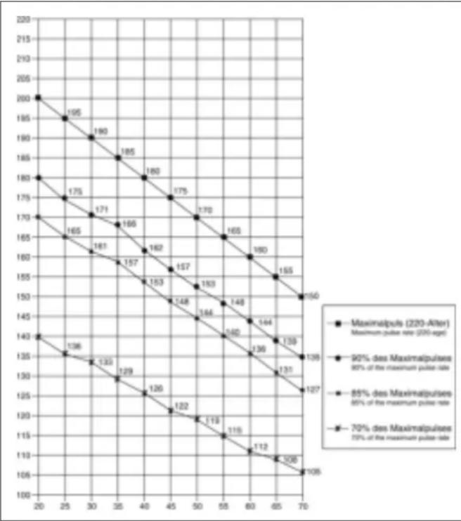
Calculation formula: Maximum pulse rate = 220 - age (220 minus your age)
90% of the maximum pulse rate = (220 - age) x 0.9
85% of the maximum pulse rate = (220 - age) x 0.85
70% of the maximum pulse rate = (220 - age) x 0.7
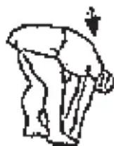
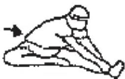
Warm up exercises (Warm Up)
Start your warm up by walking on the spot for at least 3 minutes and then perform the following gymnastic exercises to the body for the training phase to prepare accordingly. The exercises do not overdo it and only as far run until a slight drag felt. This position will hold a while.

natural_image
Simple line drawing of a person in a kneeling or stretching pose (no text or symbols)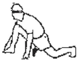
natural_image
Simple line drawing of a person in a kneeling position (no text or symbols)Reach with your left hand behind your head to the right shoulder and pull with the right hand slightly to the left elbow. After 20sec. switch arm.
Bend forward as far forward as possible and let your legs almost stretched. Show it with your fingers in the direction of toe. 2 x 20sec.
Sit down with one leg stretched out on the floor and bend forward and try to reach the foot with your hands. 2 x 20sec.
Kneel in a wide lunge forward and support yourself with your hands on the floor. Press the pelvis down. Change after 20 sec leg.
After the warm-up exercises by some arms and legs shake loose.
Don't finish the exercise phase abruptly, but will cycle leisurely something without resistance from to return to the normal pulse-zone. (Cool down) We recommend the warm-up exercises at the end of the training be conducted and to end your workout with shaking of the extremities.
Parts List – Spare Parts List RW 500 Order No. 1960
Please contact us if any components are defective or missing, or if you need any spare parts or replacements in future.
Internet service- and spare parts data base: www.christopeit-service.de
Technical data: Issue: 01.10.2019
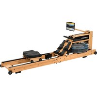
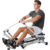
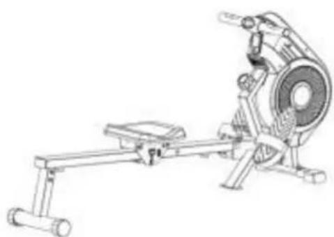
RW 500 is full body workout rowing machine. Effective training of upper body, shoulders, back, arms and legs.
Great effect with little effort
- Ideal for hull exercises
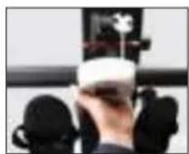
- Integrated hand pulse measurement in the drawbar
• Exercise computer with pulse - Magnet brake system
• 10-step manual resistance adjustment - Padded comfort seat with ball bearing rollers
- foldable to save space after use
- Large LCD display with digital display of: time, strokes, stroke per minute, strokes total, calories consumption and scan.
• Stable design up to a body weight of max.120 kg
Dimension approx. (L x W x H): 175 x 47 x 76 cm Dimension folded (L x W x H): 90 x 47 x 133 cm Product weight approx. 25 kg
This product is created only for private Home sports activity and not allowed to us in a commercial or professional area. Home Sport use class H/C

text_image
0 5 10 15 20 25 30 35 40 45 50 55 60 65 70 75 80 85 90 95 100 mm| Illu No. | Designation Dimensions Quantity | mm | Attached to il-lustration No. | ET number | |
| 1 | Main frame 1 3 33-1960-01-SW | ||||
| 2 | Front bottom tube 1 1 33-1960-02-SW | ||||
| 3 | Guide rail 1 1+4 33-1960-03-SW | ||||
| 4 | Rear support frame 1 3 33-1960-04-SW | ||||
| 5 | Right support frame 1 28 33-1960-05-SW | ||||
| 6 | Left support frame 1 28 33-1960-06-SW | ||||
| 7 | U baffle plate 2 5+6 33-1960-06-SW | ||||
| 8 | Handle bar 1 1 33-1860-02-SW | ||||
| 9 | Carriage bolt M8x45 | 2 1+2 39-10124-VC | |||
| 10 | Hex bolt | M12x155 | 4 | 1+37 | 39-10331-CR |
| 11 | Hex bolt | M10x105 | 1 1+3 39-10154 | ||
| 12 | Hex bolt | M8x125 | 3 | 5-6+29 | 39-10446 |
| 13 | Hex socket pan head screw | M8x16 | 10 | 3-6+28-36 | 39-9823 |
| 14 | Cross head screws | 4.2x18 | 18 | 85L+85R | 36-9111-38-BT |
| 15 | Cap nut | M8 | 2 1+2 39-9900-CR | ||
| 16 | Nylon nut | M6 | 4 | 5-6+61 | 39-9861-SW |
| 17 | Nylon nut | M8 | 3 5+6 39-9918-CR | ||
| 18 | Nylon nut | M10 | 2 1+3 39-9981 | ||
| 19 | Spring washer | for M8 | 11 | 1-6+28 | 39-9864 |
| 20 | Washer | 8//16 | 16 | 1-6+28 | 39-9862-CR |
| 21 | Washer | 10//32 | 1 | 1+30 | 39-10053 |
| 22 | Washer | 10//20 | 4 1+3 39-9989-CR | ||
| 23 | Eye bolt | M6x40 | 4 | 5-6+61 | 39-10000 |
| 24 | U-shape washer | 4 | 5-6+61 | 39-9713-56-BT | |
| 25 | Cross head screw | M5x7 | 4 7 39-9944 | ||
| 26 | Spacer | 6 5+6 36-1960-04-BT | |||
| 27 | Bearing | 6 5+6 36-1260-16-BT | |||
| 28 | Saddle | 1 5+6 36-1960-05-BT | |||
| 29 | Wheel | 3 5+6 36-1960-06-BT | |||
| 30 | Hand grip screw | M10x25 | 1 | 1+3 | 36-1260-06-BT |
| 31L | Square tube plug left | 1 3 36-1960-07-BT | |||
| 32R | Front end cap left | 1 1 36-1960-08-BT | |||
| 32 | Front end cap right | 1 1 36-1960-09-BT | |||
| 33 | Rear end cap | 2 4 36-9906310-BT | |||
| 34 | Fabric belt | 1 61 36-1960-10-BT | |||
| 35 | Foam grip | 2 8 36-1860-05-BT | |||
| 36 | Cushion | 2 3 36-1960-11-BT | |||
| 37 | Pedal 2 1 36-1260-10-BT | ||||
| 38 | Cable save 1 3 36-1660-15-BT | ||||
| 39 | Round magnet with bracket 1 5+6 36-1960-14-BT | ||||
| 40 | End cap 2 8 36-1260-21-BT | ||||
| 41 | Sensor wire 1 42 36-1960-15-BT | ||||
| 42 | Extension wire 1 41 36-1960-16-BT | ||||
| 43 | Ball cap 2 3 36-9988108-BT | ||||
| 44a | Pulse display 1 44.b+45 36-1860-03-BT | ||||
| 44b | Pulse display housing | 1 44.a+45 | 36-1860-04-BT | ||
| 45 | Pulse sensor | 2 44a 36-1860-08-BT | |||
| 46 | Cross head screws | 3.5x20 | 4 | 44a+44b | 36-1860-07-BT |
| 47 | Nut M10x1 | 2 50 39-9820 | |||
| 48 | Flywheel axle | 2 50+56 | 36-1960-17-BT | ||
| 49 | Bearing | 4 48 36-1960-18-BT | |||
| 50 | Fabric belt wheel | 1 45L-45R+48 | 36-1960-19-BT | ||
| 51 | Pin | 1 50 36-1960-20-BT | |||
| 52 | Washer 10//14 | 1 56 36-1121 | |||
| 53 | Bearing | 2 48+50 | 36-1960-21-BT | ||
| 54 | Bearing seat | 1 48+50 | 36-1960-22-BT | ||
| 55 | Free wheel bearing | 1 48+50 | 36-1960-23-BT | ||
| 56 | Belt wheel 1 48 36-1960-24-BT | ||||
| 57 | Cross countersunk head screw | 4.2x15 | 4 | 58+61 | 39-9943 |
| 58 | Aluminum ring | 1 61 36-1960-25-BT | |||
| 59 | Nut M10x1 | 2 48+61 | 39-9820-SI | ||
| 60 | Spacer | 1 48+61 | 36-1960-26-BT | ||
| 61 | Fan wheel | 1 85L-85R+48 | 36-1960-27-BT | ||
| 62 | Axle nut thin | M10x1 | 1 | 48+61 | 39-9820-SW |
| 63 | Sleeve 1 | 2 64 36-1960-28-BT | |||
| 64 | Pulley | 1 1 36-1960-29-BT | |||
| 65 | Hex bolt M10x105 | 1 64 39-1053 | |||
| 66 | Grip storage | 1 1 36-1960-30-BT | |||
| 67 | Computer | 1 1 36-1960-03-BT | |||
| 68 | Air outlet | 1 1 36-1960-31-BT | |||
| 69 | Secure ring | 5 1 36-1960-32-BT | |||
| 70 | Spring washer | 5 1 36-1260-30-BT | |||
| 71 | Bearing | 5 1 36-1960-33-BT | |||
| 72 | Wheel | 5 1 36-1960-34-BT | |||
| 73 | Snap spring | 5 1 36-1960-35-BT | |||
| 74 | Belt | 1 56+61 | 36-1960-36-BT | ||
| 75 | Spring | 1 79 36-1960-37-BT | |||
| 76 | Hex bolt M8x20 | 1 80 39-10095-SI | |||
| 77 | Washer 8//32 | 1 80 30-10166 | |||
| 78 | Sleeve 2 | 2 80 36-1960-38-BT | |||
| 79 | Magnetic bracket | 1 1 36-1960-12-BT | |||
| 80 | Axle Nut M10x1 | 4 51+61 | 39-9820 | ||
| 81 | Cross tapping Screw M5x15 | 4 66 36-9329712-BT | |||
| 82 | Tension controller | 1 1 36-1260-04-BT | |||
| 83 | Washer 5//20 | 1 82 39-10011 | |||
| 84 | Cross tapping Screw | 1 82 36-9329713-BT | |||
| 85L | Chain cover left | 1 1+85R | 36-1960-01-BT | ||
| 85R | Chain cover right | 1 | 1+85L | 36-1960-02-BT | |
| 86 | Rope | 1 8+50 | 36-1960-13-BT | ||
| 87 | Tool Set | 1 | 36-1960-39-BT | ||
| 88 | Assembly and exercise instructions | 1 | 36-1960-40-BT | ||
text_image
Technical diagram of a mechanical assembly with numbered components, likely for engineering or manufacturing documentation.Étape n° 2:
text_image
Technical diagram of a mechanical device with numbered components and labeled partsÉtape n° 4:
text_image
Technical diagram of a stationary exercise machine with numbered components and labeled partsÉtape n° 5:
text_image
Technical diagram of a stationary exercise machine with numbered components and labeled partsÉtape n° 6:
text_image
Technical diagram of a stationary exercise machine with numbered components and motion arrows indicating rotation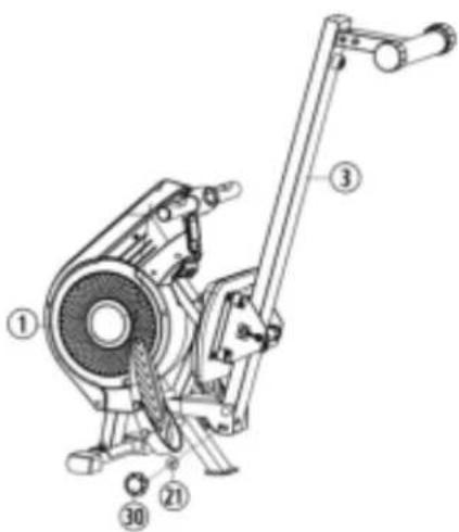
text_image
Technical diagram of a mechanical device with numbered components labeled ①, ②, ③, and ④.Étape n° 7:
Contrôle
natural_image
Line drawing of a stationary exercise machine with lever and wheels (no text or symbols)Ecran Pulse (Pulsation):
natural_image
Person using an olive oil retable exercise in a gym (no visible text or symbols)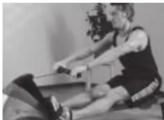
natural_image
Person performing a rowing exercise on a machine (no visible text or symbols)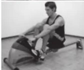
natural_image
Person performing a rowing exercise on an outdoor machine (no visible text or symbols)line
| X-axis | Maximalpuls (220-After) Maximum pulse rate (220-age) | 90% des Maximalpulses 90% of the maximum pulse rate | 85% des Maximalpulses 85% of the maximum pulse rate | 70% des Maximalpulses 70% of the maximum pulse rate | |---|---|---|---|---| | 20 | 200 | 195 | 190 | 170 | | 25 | 195 | 190 | 185 | 165 | | 30 | 190 | 185 | 180 | 161 | | 35 | 185 | 180 | 175 | 157 | | 40 | 180 | 175 | 170 | 153 | | 45 | 175 | 170 | 165 | 148 | | 50 | 170 | 165 | 160 | 144 | | 55 | 165 | 160 | 155 | 140 | | 60 | 160 | 155 | 150 | 136 | | 65 | 155 | 150 | 145 | 131 | | 70 | 150 | 145 | 140 | 127 | The chart displays a single line representing the maximum pulse rate for maximal pulses at different thresholds. The x-axis ranges from 20 to 70, and the y-axis ranges from 100 to 220. Each line corresponds to a specific threshold value, with numerical labels indicating the pulse rate value at each point. The chart is annotated with a number (e.g., “Maximalpuls (220-After)”). The title explicitly states that the data represents the maximum pulse rate for maximal pulses at these thresholds. The legend clarifies that higher pulse rates correspond to lower maximum pulse rates.natural_image
Simple line drawing of a person in a kneeling pose, wearing a helmet and holding an object (no text or symbols)natural_image
Simple line drawing of a person in a kneeling or stretching pose (no text or symbols)text_image
Technical diagram of a mechanical assembly with numbered components for identificationStap 2 :
text_image
Technical diagram of a mechanical device with numbered components and labeled partsStap 4 :
text_image
Technical diagram of a stationary exercise machine with numbered components and labeled partsStap 5 :
natural_image
Line drawing of a stationary exercise machine with lever and head assembly (no text or symbols)Computerhandleiding
natural_image
Person using a rowing machine in a gym (no visible text or symbols)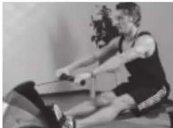
natural_image
Black-and-white photo of a person performing a rowing exercise on a machine (no visible text or symbols)
natural_image
Person performing a rowing exercise on an outdoor machine (no visible text or symbols)Oefenterrein in mm (Voor de apparaat-en gebruikers)
Oefenterrein in mm (Voor de apparaat-en gebruikers)
text_image
2000 1750 470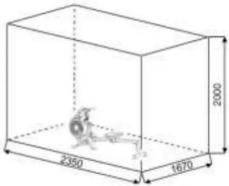
text_image
2000 2350 16703. Planning van de training
line
| X-axis | Maximalpuls (220-Alter) Maximum pulse rate (20%-age) | 90% des Maximalpulses 80% of the maximum pulse rate | 85% des Maximalpulses 80% of the maximum pulse rate | 70% des Maximalpulses 70% of the maximum pulse rate | |---|---|---|---|---| | 20 | 260 | 195 | 190 | 170 | | 25 | 195 | 175 | 171 | 165 | | 30 | 190 | 171 | 166 | 161 | | 35 | 185 | 165 | 160 | 157 | | 40 | 180 | 162 | 157 | 153 | | 45 | 175 | 157 | 153 | 148 | | 50 | 170 | 153 | 148 | 144 | | 55 | 165 | 148 | 144 | 140 | | 60 | 160 | 144 | 139 | 136 | | 65 | 155 | 139 | 134 | 131 | | 70 | 150 | 134 | 129 | 127 | | 75 | 145 | 129 | 124 | 120 | | 80 | 140 | 124 | 119 | 115 | | 85 | 135 | 119 | 114 | 112 | | 90 | 130 | 114 | 109 | 106 | The chart displays a single line graph representing the relationship between pulse rate and maximal pulses. The x-axis ranges from '20' to '70', and the y-axis ranges from '100' to '220'. The legend indicates four distinct percentiles: 'Maximalpuls (220-Alter)', '90% des Maximalpulses', '85% des Maximalpulses', and '70% des Maximalpulses'. The data points are labeled with their respective numerical values along the vertical axis.natural_image
Simple line drawing of a person in a kneeling or stretching pose (no text or symbols)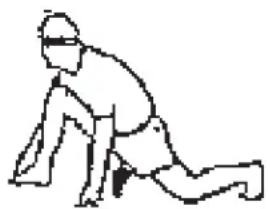
natural_image
Simple line drawing of a person in a kneeling or stretching pose (no text or symbols)text_image
Technical diagram of a mechanical assembly with numbered components and labeled partstext_image
Technical diagram of a mechanical device with numbered parts for identificationtext_image
Technical diagram of a stationary exercise machine with numbered components and labeled partstext_image
Technical diagram of a stationary exercise machine with numbered components and labeled partsnatural_image
Line drawing of a stationary exercise machine with levers and wheels (no text or symbols)natural_image
Person using a rowing exercise machine in a gym (no visible text or symbols)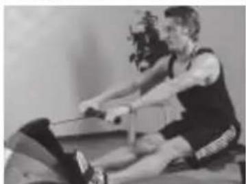
natural_image
Person performing a rowing exercise on a machine (no visible text or symbols)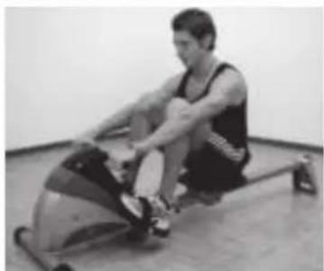
natural_image
Person performing a rowing exercise on an outdoor stationary bike (no visible text or symbols)line
| X-axis | Maximalpuls (220-After) Maximum pulse rate (230-age) | 90% des Maximalpulses 90% of the maximum pulse rate | 85% des Maximalpulses 85% of the maximum pulse rate | 70% des Maximalpulses 70% of the maximum pulse rate | |---|---|---|---|---| | 20 | 200 | 195 | 180 | 170 | | 25 | 195 | 190 | 175 | 165 | | 30 | 190 | 185 | 171 | 161 | | 35 | 185 | 180 | 166 | 157 | | 40 | 180 | 175 | 162 | 153 | | 45 | 175 | 170 | 157 | 148 | | 50 | 170 | 165 | 153 | 144 | | 55 | 165 | 160 | 148 | 140 | | 60 | 160 | 155 | 144 | 136 | | 65 | 155 | 150 | 139 | 131 | | 70 | 150 | 145 | 134 | 127 | | 75 | 145 | 140 | 129 | 122 | | 80 | 140 | 135 | 124 | 119 | | 85 | 135 | 130 | 119 | 115 | | 90 | 130 | 125 | 114 | 112 | | 95 | 125 | 120 | 109 | 106 | The chart displays a single line graph representing the maximum pulse rate for each pulse rate category. The x-axis ranges from '20' to '70', and the y-axis ranges from '100' to '220'. The legend indicates four distinct pulse rate categories: 'Maximalpuls (220-After)', '90% des Maximalpulses', '85% des Maximalpulses', and '70% des Maximalpulses'. The data points are explicitly labeled with their respective numerical values, indicating that the maximum pulse rate increases as the percentage of maximalpulse rate decreases. The chart is saved as a PNG file named 'maximalpuls'.natural_image
Simple line drawing of a person in a kneeling pose (no text or symbols)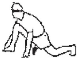
natural_image
Simple line drawing of a person in a kneeling position (no text or symbols)text_image
Technical diagram of a mechanical device with numbered components for identification and assembly reference.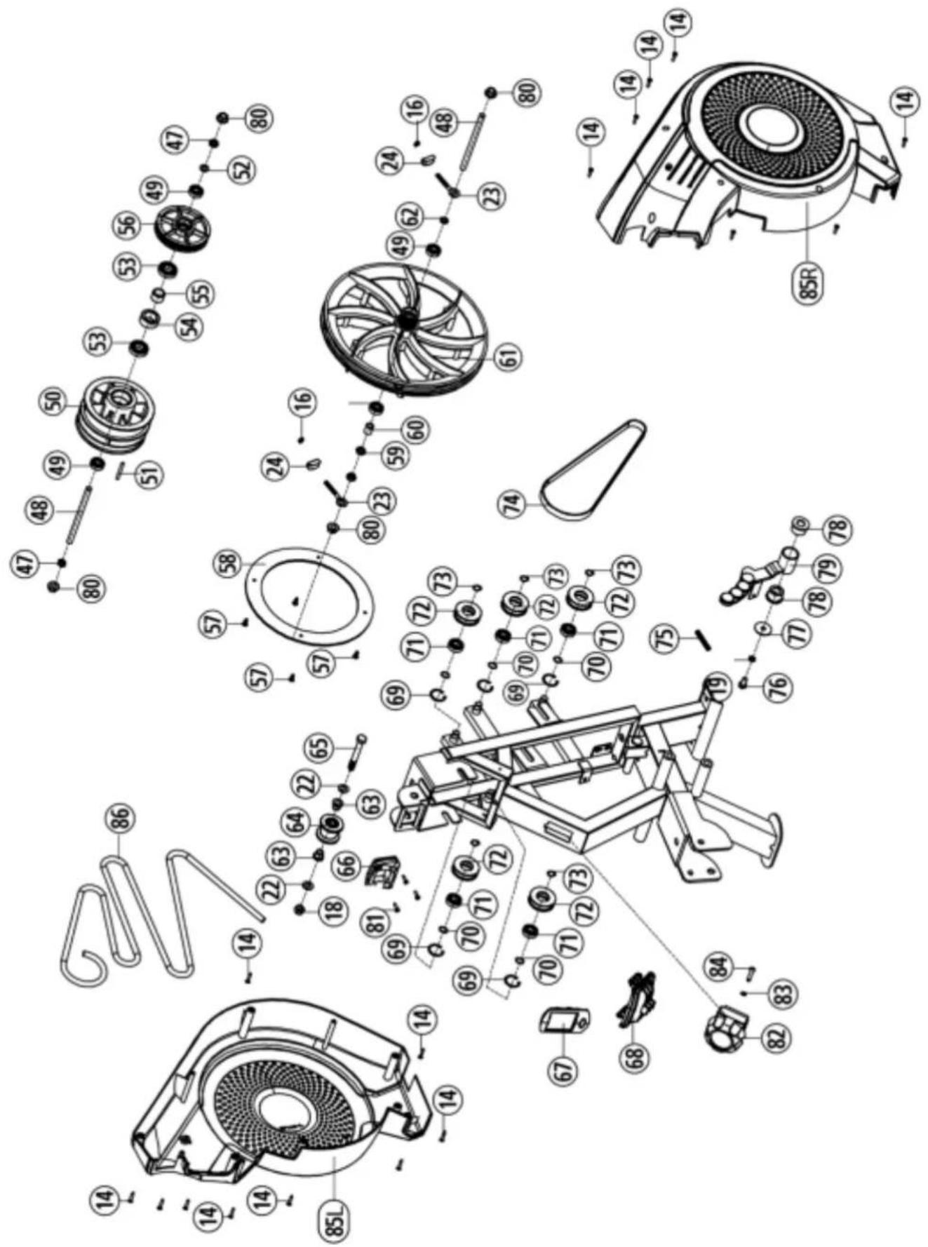
text_image
Exploded view diagram of a mechanical fan assembly with numbered components and exploded views© by Top-Sports Gilles GmbH D-42551 Velbert (Germany)
Service:
Top-Sports
Gilles
GmbH
Tel.: +49 (0)2051/6067-0
Friedrichstrasse 55
info@christopeit-sport.com
Fax: +49 (0)2051/6067-44
D - 42551 Velbert http://www.christopeit-sport.com

CHRISTOPEIT®
SPORT GERMANY
项目