Garda - Rowing Machine Christopeit - Free user manual and instructions
Find the device manual for free Garda Christopeit in PDF.

User questions about Garda Christopeit
0 question about this device. Answer the ones you know or ask your own.
Ask a new question about this device
Download the instructions for your Rowing Machine in PDF format for free! Find your manual Garda - Christopeit and take your electronic device back in hand. On this page are published all the documents necessary for the use of your device. Garda by Christopeit.
USER MANUAL Garda Christopeit
Assembly and operating instructions
Order No.: 2461 GB
Page: 13-22

natural_image
Man performing a rowing machine on a white background, no visible text or symbolsINHALTSÜBERSICHT
InhaltSeite
text_image
Technical diagram of a mechanical assembly with numbered components and directional arrows indicating motion or assembly steps.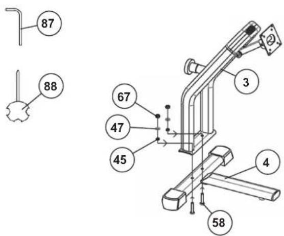
text_image
87 88 67 47 45 3 4 58SCHRITT 4
text_image
On/Off 75 89 18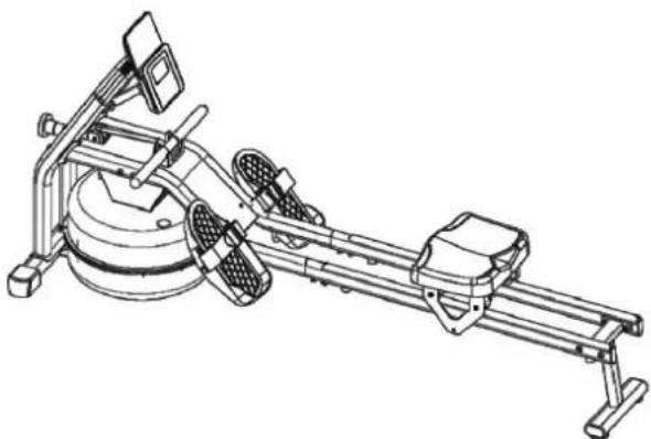
natural_image
Technical line drawing of a rowing machine with levers and wheels (no text or symbols)natural_image
Two black-and-white photos of a man performing a rowing machine on either side (no text or symbols visible)natural_image
Diagram showing a stationary exercise machine before and after assembly, with no visible text or symbolsSTÖRUNGSBESEITIGUNG
natural_image
Sequence of four sequential illustrations showing a person performing a stretching or kneeling movement (no text or symbols)| 13 | Important recommendations and safety instructions |
| 14-16 | Assembly instructions |
| 17 | Computer |
| 18 | Kinomap App |
| 18 | Operating and exercising instructions |
| 19 | Cleaning, checks and storage |
| 19 | Troubleshooting |
| 20 | General training instructions |
| 21-22 | Parts list – Spare parts list |
| 54 | Declaration of conformity |
| 55 | Exploded drawing |
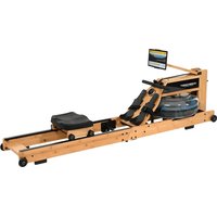
We congratulate you on your purchase of this home training sports unit and hope that we will have a great deal of pleasure with it. Please take heed of the enclosed notes and instructions and follow them closely concerning assembly and use. Please do not hesitate to contact us at any time if you should have any questions.
text_image
Attention! Before use read operating instructions!IMPORTANT RECOMMENDATIONS AND SAFETY INSTRUCTIONS
Our products are all TÜV tested and therefore represent the highest current safety standards. However, this fact does not make it unnecessary to observe the following principles strictly.
-
Assembly the machine exactly as described in the installation instructions and use only the enclosed, specific parts of the machine. Before assembling, verify the completeness of the delivery against the delivery notice and the completeness of the carton against the assembly steps in the installation and operating instructions.
-
Check the firm seating off all screws, nuts and other connections before using the machine for the first time and at regular intervals to ensure that the trainer is in a safe condition.
-
Set up the machine in a dry, level place and protect it from moisture and water. Uneven parts of the floor must be compensated by suitable measures and by the provided adjustable parts of the machine if such are installed. Ensure that no contact occurs with moisture or water.
-
Place a suitable base (e.g. rubber mat, wooden board etc.) beneath the machine if the area of the machine must be specially protected against indentations, dirt etc.
-
Before beginning training, remove all objects within a radius of 2 metres from the machine.
-
Do not use aggressive cleaning agents to clean the machine and employ only the supplied tools or suitable tools of your own to assemble the machine and for any necessary repairs. Remove drops of sweat from the machine immediately after finishing training.
-
Attention! Systems of the heart frequency supervision can be inexact. Excessive training can lead to serious health damage or to the death. Consulta doctor before beginning a planned training programme. He can define the maximum exertion (pulse, Watts, duration of training etc.) to which you may expose yourself and can give you precise information on the correct posture during training, the targets of your training and your diet. Never train after eating large meals. This item is not suitable for therapeutically purposes!
-
Only train on the machine when it is in correct working order. Use original spare parts only for any necessary repairs. Attention! Replace the worm parts immediately and keep this equipment out of use until repaired.
-
When setting the adjustable parts, observe the correct position and the marked, maximum setting positions and ensure that the newly adjusted position is correctly secured.
-
Unless otherwise described in the instructions, the machine must only be used for training by one person at a time. The exercise time should not overtake 60 min/daily.
-
Wear training clothes and shoes which are suitable for fitness training with the machine. Your clothes must be such that they cannot catch during training due to their shape (e.g. length). Your training shoes should be appropriate for the trainer, must support your feet firmly and must have non-slip soles.
-
Attention! If you notice a feeling of dizziness, sickness, chest pain or other abnormal symptoms, stop training and consult a doctor.
-
Never forget that sports machines are not toys. They must therefore only be used according to their purpose and by suitably informed and instructed persons.
-
People such as children, invalids and handicapped persons should only use the machine in the presence of another person who can give aid and advice. Take suitable measures to ensure that children never use the machine without supervision. Ensure that the person conducting training and other people never move or hold any parts of their body into the vicinity of moving parts.
-
It must be ensured that the user and other people never go or stand with any body parts in the area of still moving parts.
-
☒ At the end of its life span this product is not allowed to dispose over the normal household waste, but it must be given to an assembly point for the recycling of electric and electronic components. You may find the symbol on the product, on the instructions or on the packing. The materials are reusable in accordance with their marking. With the re-use, the material utilization or the protection of our environment. Please ask the local administration for the responsible disposal place.
-
To protect the environment, do not dispose of the packaging materials, used batteries or parts of the machine as household waste. Put these in the appropriate collection bins or bring them to a suitable collection point.
-
The maximum permissible load (=body weight) is specified as 120 kg.
-
Do not overfill the water tank and pay attention to the max. marking of water level. If the tank is overfilled, water can escape during training or when the device is transported and cause damage. Use normal tap water as this already has additives that do inhibit algae growth. After about 6-12 months (depending on usage), it makes sense to replace the water, as the additives have been used up. Alternatively, you can use 1 chlorine tablet to treat the water and protect the tank from sedimentations. A cleaning process of the inner tank with all parts located there is then done automatically by the training.
-
The assembly and operating instructions is part of the product. If selling or passing to another person the documentation must be provided with the product.
ASSEMBLY INSTRUCTIONS
Remove all the separate parts from the packaging, lay them on the floor and check roughly that all are there on the base of the assembly steps. Please note that a number of parts have been connected directly to the main frame and preassembled. The screw material required for assembly is located on the components to be assembled. This will make it easier and quicker for you to assemble the equipment. Assembly time: 30 - 40 min.
STEP 1
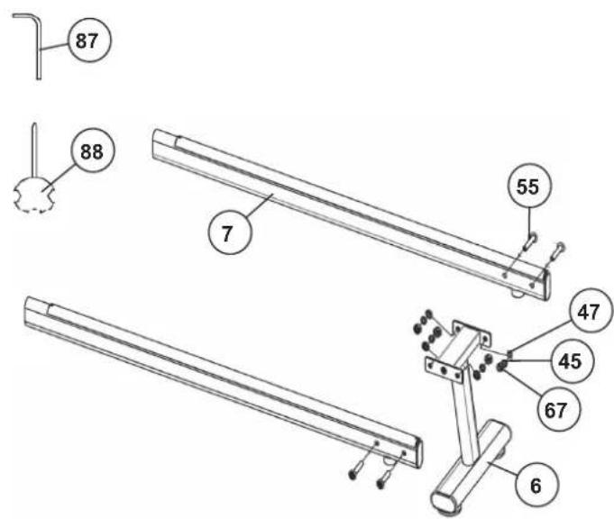
Attach the rear foot (6) at seat slide (7).
- Put the rear foot (6) into the holder at seat frame (7) and screw it tightly by using 4 screws M8x40 (55), washers (47), spring washers (45) and nylon nuts (67).
STEP 2
Attach the seat (24).
- Push the seat frame (7) through the seat slide (5) as showed, so that 4 pulleys can roll onto the top side and 2 pulleys can roll onto the bottom side of seat frame (7).
- Fix the cushion pad (38) at appropriate position on bottom side of seat frame (7) with screw M6x16 (60).
STEP 3
Attach the front foot (4) at front frame (3).
- Place the front foot (4) into the holder of front frame (3) and screw it tightly by using 2 screws M8x45 (58), washers (45), spring washers (47) and nylon nuts (67).

text_image
87 88 7 55 47 45 67 6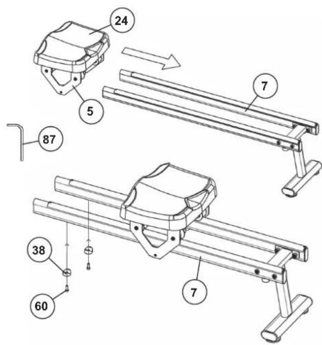
text_image
Technical diagram of a mechanical assembly with numbered components and directional arrows indicating motion or assembly steps.
text_image
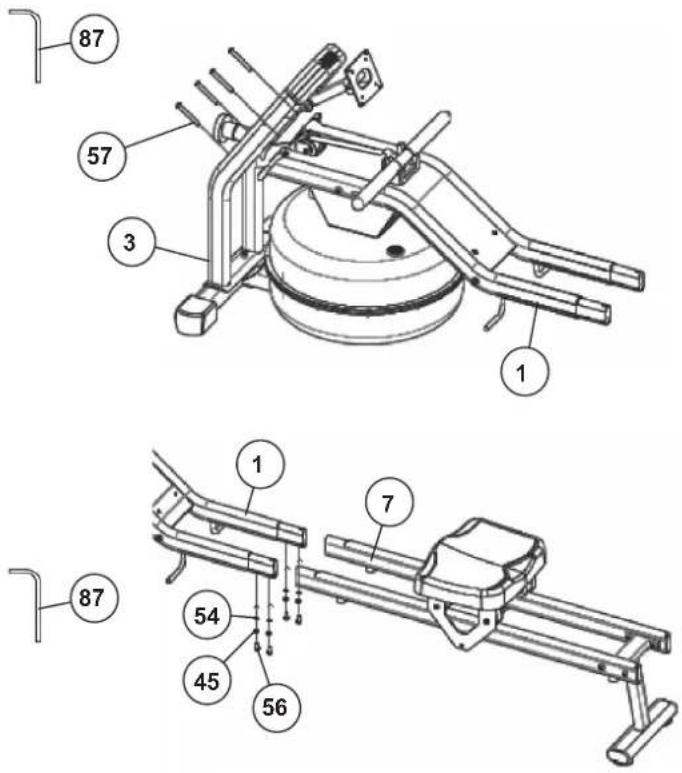
87 88 67 47 45 3 4 58STEP 4
Attach the front frame (3) at main frame (1).
- Put the front frame (3) into the holder of main frame (1), so that the holes pattern and tighten the front frame (3) at main frame (1) with screws M8x60 (57).
STEP 5
Attach the seat frame (7) at main frame (1).
- Push the seat frame (7) into the holder of main frame (1), so that the holes pattern. Put on each screw M8x15 (56) one spring washer (45) and washer (54) tighten then the seat frame (7) at main frame (1).
text_image
87 57 3 1 1 7 54 45 56 87STEP 6
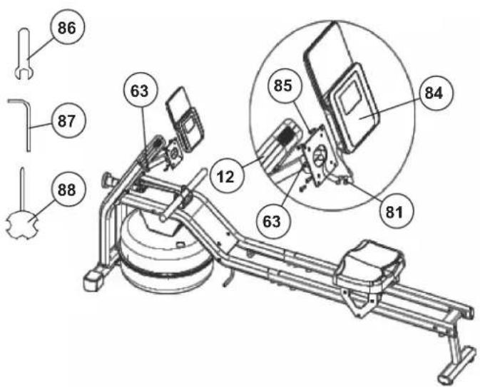
Attach the computer (84) at computer holder (12).
-
Insert the batteries (Type AAA - 1.5V) onto the back of the computer (84), observing the correct polarity. (Batteries for the computer are not included in the scope of delivery. Please purchase them from retailers.) Plug the two connection cables (81) into the corresponding connection sockets on the computer (84) and stow the cable connections as much as possible in computer (84) and in the computer holder (12). Put the computer (84) onto the computer holder (12), so that the holes pattern and screw it tight using the screw M4x10 (85). The screws (85) for the computer are pre-assembled on the backside of computer. Make sure that no cables are crushed.
-
Put the computer (84) into desired position for a good view and fix the position with screws (63) so the computer can be a little difficult to correct.
text_image
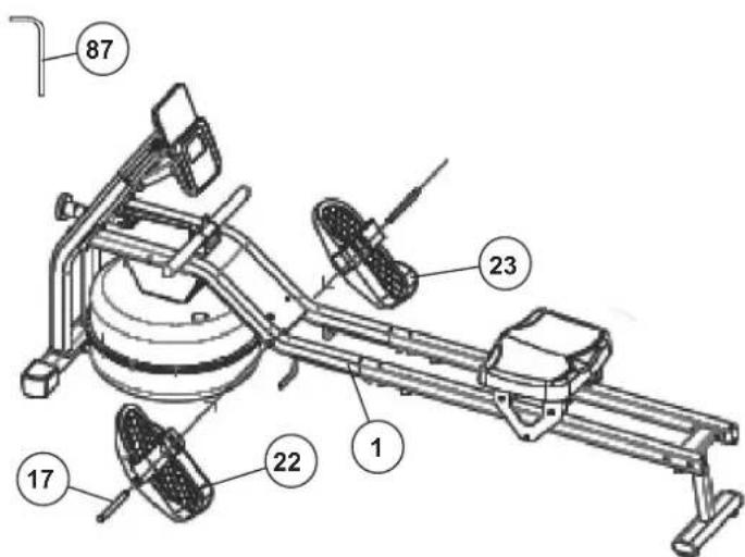
Technical diagram of a rowing machine with numbered components and an inset close-up view showing internal parts.STEP 7
Attach the foot pedals (22+23) at main frame (1).
- Screw the foot plates (22+23) by using the screws M12x150 (17) into the appropriate position at the bottom of main frame (1). The foot plates are marked on backside with L for Left and R for Right. The long, raised edge of the footrests must point towards the base frame.
text_image
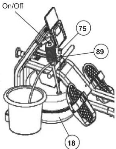
87 23 17 22 1STEP 8
Refill the water tank (18).
- Use tap water from a bucket to refill water tanks (18). Remove the filling plug (75) from the water tank, insert the flexible pipe end of the water pump (89) approx. 10 cm into the water tank (18) and the rigid pipe end into the bucket with water.
- Turn on the screw cap and press the hand bellows to pump the water into the tank (18). (If the bucket position is higher than the tank the water will flow automatically into the tank after pressing some hand bellows. Turn off the screw cap to interrupt the water flow.) The tank has a mark for the max. water level. This maximum limit may not be exceeded. If the tank (18) is overfilled, water will spill out during transport and during training and may cause damage.
- We recommend refill the water level slightly below max. level, as this is the optimal rowing resistance given. The desired intensity during training is freely selectable by the speed of the rowing. For less water resistance you can remove water from the tank by means of the hand pump (89) by swapping the pipe ends of the hand pump.
- When setting up the device, be careful not to expose it to direct sunlight, as this promotes algae growth.
text_image
On/Off 75 89 18CHECKS
- Check the correct installation and function of all screwed and plug connections. Installation is thereby complete.
- When everything is in order, familiarise yourself with the machine at a low resistance setting and make your individual adjustments.
Note: Please keep the tool set and the instructions in a safe place as these may be required for repairs or spare parts orders becoming necessary later.
natural_image
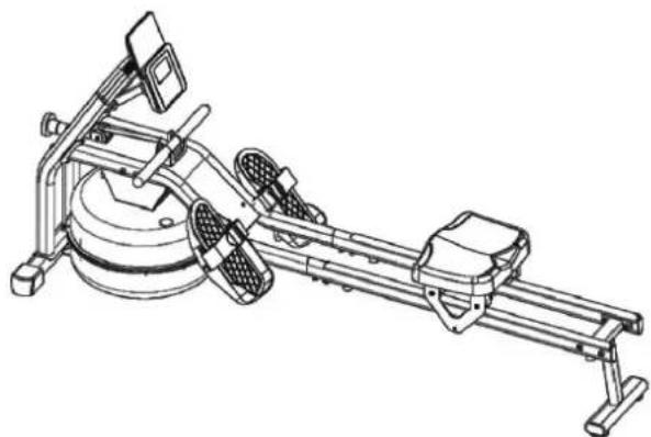
Technical line drawing of a rowing machine with levers and wheels (no text or symbols)COMPUTER DESCRIPTION
The included computer offers the greatest training comfort. Each training-relevant value is displayed. From the start of training, the training time, strokes, distance, calories, total strokes and pulse (optional) are displayed. All values are recorded counting upwards from zero. If you want to have a value permanently displayed during training, select it using the [M] key. A specific value can be set using the [E] button. If the specified value is reached, this is indicated by an acoustic signal.
The computer switches on by briefly pressing the [M] button or simply starting training. The computer begins to collect and display all values. To stop the computer, simply stop training. The computer stops all measurements and records the last values reached. The last values reached in the functions training time, strokes, calories and total strokes are saved for 4 minutes and when training is resumed, training can continue from these values. The computer will automatically turn off approximately 4 minutes after you finish training.
DISPLAY
[SCAN]:
The current values of all functions are displayed one after the other in a continuous alternation of approx. 6 seconds.
[TIME] Time:
The currently required time is displayed in minutes and seconds.
[DIST] Distance:
The current status of the kilometers covered is displayed.
[COUNT] Rowing strokes:
The current rowing strokes are displayed.
[CAL] Calories:
The current number of calories is displayed in approx. (Kcal).
[TCNT] Rowing strokes total:
The total number of rowing strokes completed in all training sessions is displayed. The data on this display is only deleted when the batteries are replaced.
[P] Pulse:
The current pulse is displayed in beats per minute. (only when using the optional Bluetooth heart rate belt.)
KEYS
1. [E-Enter]:
By pressing this key once, it is possible to specify values step by step in the respective functions. For this, the desired function must firstly be selected using the [M] key. Holding the key pressed activates faster running. When training begins, the specified values are then counted down to zero.
2. [M-Mode]:
Pressing this key once briefly makes it possible to change from one function to another, i.e. the respective functions can be selected for which entries can be made using the [E] key. The currently selected function is indicated in the window.
3. [R-Reset]
When this key is pressed briefly, the values chosen with the [M] key are reset to zero. If the key is held longer (approx. 3 seconds), all last attained values, except for total strokes are deleted.
![Christopeit Garda - [R-Reset] - 1](/content/2026/04/710204/images/16bb56d6ff681b75217bb8e847090853c26256caea88ac680742ac68af5291dc.jpg)
text_image
CHRISTOPEIT® SPORT GERMANY 0.20 DIST E ENTER M MODE R RESETPULSE RATE
Pulse belt pulse measurement
Optionally, you can use a compatible Bluetooth heart rate belt to measure your heart rate (Christopeit-Sport heart rate belt 2209). The measured pulse value is displayed in the heart rate display. Response time is up to 60 seconds.
Attention! The heart rate measurement is not for medical purposes suitable.
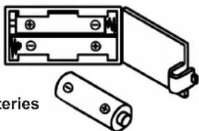
REPLACING THE BATTERIES
- Open the battery compartment cover and then remove the used batteries.(If the batteries should leak remove them under increased considering that the battery acid is not into contact with skin come and clean the battery compartment thoroughly.)
- Insert the new batteries (type (AAA) 1.5 V in the correct order and taking into account the polarity in the battery compartment and close the battery cover so that it clicks into place.
- If the computer does not pick up immediately, the function should batteries are removed for 10 seconds and re-inserted.
- The empty batteries properly in accordance with the disposal regulations disposed of and do not give residual waste.
Battery compartment
AAA Batteries
natural_image
Diagram of two battery components with labeled parts, no text or symbols presentAPP CONNECTIVITY
KINOMAP APP
Sport, coaching, gaming and eSport are the keywords of the Kinomap app. This contains many kilometers of real film material to exercise inside as if you were outside; Tracking routes and analysis of your performance; Coaching content; Multiplayer mode; new posts daily; Official indoor races and more ...
Download the app and connect
Scan the adjacent QR code with your smartphone / tablet or use the search function at the Playstore (Android) or APP Store (IOS) to download the Kinomap APP. Register and follow the instructions in the APP. Activate Bluetooth on the smartphone or tablet and select the device manager in the app and then the appropriate product category there. Then select your type designation using the manufacturer logo "Christopeit Sport" to connect the sports equipment. Depending on the sports equipment, different functions are recorded by the APP via Bluetooth or data is exchanged.
Attention! The Kinomap app offers a free trial version for 14 days. You can then decide whether you want to continue training for free with the basic version or use the full range of the Kinomap app for a fee.
Current information and fees can be found at:
www.kinomap.com
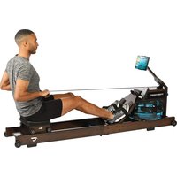
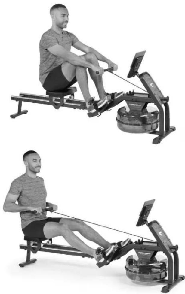
a) Begin this exercise with your legs straight, knees together and the upper part of your body upright.
b) Bend forward without bending your knees, grip the handle bar and pull back until the upper part of your body is upright again. Important: The oar levers should be pulled back with the arms (and not with the body) until your hands have reached your body.
c) Bring the handle bar back to the starting position again.
d) Rest for a moment and then carry out the exercise again, repeating it quietly and continuously.
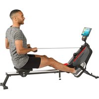
Exercise 2
a) Begin this exercise sitting upright with the seat as far forward as possible and your knees bent.
b) Push back with the legs keeping your knees together and at the same time pulling the handle bar towards you.
c) Continue pulling until your legs are straight and your hands have reached your body.
d) Relax your arms and legs and let the seat slide forward until you have reached the start position (a) again and then repeat the exercise again.
natural_image
Two black-and-white photos of a man performing a rowing machine on either side (no text or symbols visible)CLEANING, CHECKS AND STORAGE
1. Cleaning
Use only a less wet cloth for cleaning. Caution: Never use benzene, thinner or other aggressive cleaning agents for surface cleaning as this damage caused. The device is only for private home use and for use suitable indoors. Keep the unit clean and moisture from the device.
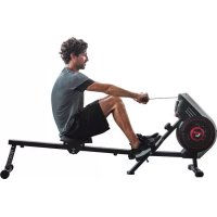
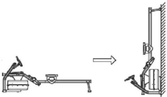
2. Storage
To change the installation location, lift the rear of the device so that it rests on the transport wheels. You can store the device upright. Remove the batteries from the computer if you will not be using the device for more than 4 weeks. Choose a dry storage location in the house. Cover the device to protect it from discoloration caused by sunlight and dust.
3. Checks
We recommend checking the screw connections made during assembly to ensure they are tight every 50 hours of operation.
natural_image
Diagram showing a stationary exercise machine and its vertical support structure (no text or symbols)TROUBLESHOOTING
If you cannot solve the problem with the following information, please contact the authorized service center.
| Problem Possible Cause Solution | ||
| Computer has no value at Display if you press any key. | No Batteries insert or batteries empty Check | the position of batteries at battery compartment or replace batteries. |
| Computer is not counting data and do not switch on after start cycling. | Sensor impulse missing base on not well plugged connection | Check the plug connections at computer and under the fold up constrcution. |
| Computer is not counting data and do not switch on after start cycling. | Sensor impulse missing base on not correct position of sensor. | Check the distance from the sensor to the magnet. A magnet is attached to the drawstring winding and should pass the sensors at a distance of less than < 5mm. |
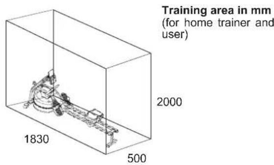
TRAINING SPACE REQUIREMENT
text_image
Training area in mm (for home trainer and user) 1830 500 2000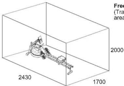
text_image
Free (Tra area) 2000 2430 1700Free area in mm
(Training area and security area (circulating 600mm))
GENERAL TRAINING INSTRUCTIONS
You must consider the following factors in determining the amount of training effort required in order to attain tangible physical and health benefits.
INTENSITY
The level of physical exertion during training must exceed the point of normal exertion, without going beyond the point of breathlessness and/or exhaustion. A suitable reference value can be the pulse. With each training session, the condition increases and therefore the training requirements should be adjusted. This is possible by extending the duration of the training, increasing the level of difficulty or changing the type of training.
TRAINING HEART RATE
To determine the training heart rate, you can proceed as follows. Please note that these are guide values. If you have health problems or are unsure, consult a doctor or fitness trainer.
01 Maximum heart rate calculation
The maximum pulse value can be determined in many different ways, since the maximum pulse depends on many factors. You can use the main-formula for the calculation (maximum heart rate = 220 - age). This formula is very general. It is used in many home sport products to determine the maximum heart rate. We recommend the Sally-Edwards-formula. This formula calculates the maximum heart rate more precisely and takes gender, age and body weight into account.
Sally-Edwards-formula:
Men:
Maximum heart rate = 214 - (0.5 x age) - (0.11 x body weight)
Women:
Maximum heart rate = 210 - (0.5 x age) - (0.11 x body weight)
02 Training heart rate calculation
The optimal training heart rate is determined by the goal of the training. Training zones were defined for this.
Health - Zone: Regeneration and Compensation
Suitable for: Beginners
Type of training: very light cardio training
Goal: recovery and health promotion. Building the basic condition.
Training heart rate = 50 to 60% of the maximum heart rate
Fat-Metabolism - Zone: Basics endurance training 1
Suitable for: beginners and advanced users
Type of training: light cardio training
Goal: activation of fat metabolism (calorie burning). improvement in endurance performance.
Training heart rate = 60 to 70% of the maximum heart rate
Aerobic - Zone: Basics endurance training 1 to 2
Suitable for: beginners and advanced
Type of training: moderate cardio training.
Goal: Activation of the fat metabolism (calorie burning), improving aerobic performance, Increase in endurance performance.
Training heart rate = 70 to 80% of the maximum heart rate
Anaerobic - Zone: Basics endurance training 2
Suitable for: advanced and competitive athletes
Type of training: moderate endurance training or interval training
Goal: improvement of lactate tolerance, maximum increase in performance.
Training heart rate = 80 to 90% of the maximum heart rate
Competition - Zone: Performance / Competition Training
Suitable for: athletes and high-performance athletes
Type of training: intensive interval training and competition training /
Goal: improvement of maximum speed and power.
Attention! Training in this area can lead to overloading of the cardiovascular system and damage to health.
Training heart rate = 90 to 100% of the maximum heart rate
Sample calculation
Male, 30 years old and weighs 80 kg. I am a beginner and would like to lose some weight and increase my endurance.
01: Maximum pulse - calculation
Maximum heart rate = 214 - (0.5 x age) - (0.11 x body weight)
Maximum heart rate = 214 - (0.5 x 30) - (0.11 x 80)
Maximum pulse = approx. 190 beats/min
02: Training heart rate calculation
Due to my goals and training level, the fat metabolism zone suits me best.
Training heart rate = 60 to 70% of the maximum heart rate
Training heart rate = 190 x 0.6 [60%]
Training heart rate = approx. 114 beats/min
After you have set your training heart rate for your training condition or Once you have identified goals, you can start training. Most of our endurance training equipment have heart rate sensors or are heart rate belt compatible. So you can check your heart rate on the monitor during the workouts. If the pulse rate is not shown on the computer display or you want to be on the safe side and want to check your pulse rate, which could be incorrectly displayed due to possible application errors or similar, you can use the following tools:
a. Pulse measurement in the conventional way (sensing the pulse beat, e.g. on the wrist and counting the beats within a minute).
b. Heart rate measurement with suitable and calibrated heart rate measuring devices (available from medical supply stores).
c. Heart rate measurement with other products such as heart rate monitors, smartphones....
FREQUENCY
Most experts recommend the combination of a health-conscious diet, which must be adjusted according to the training goal, and physical exercise three to five times a week. A normal adult needs twice a week exercise to maintain its current condition. To improve his condition and change his body weight, he needs at least three training sessions per week. Ideal of course is a frequency of five training sessions per week.
TRAINING PLAN
Each training session should consist of three training phases: "warmup phase", "training phase" and "cool-down phase". In the "warm-up phase" the body temperature and the oxygen supply should be increased slowly. This is possible through gymnastic exercises over a period of five to ten minutes. After that you start with actual training "training phase". The training load should be adapted according to the training heart rate. In order to support the circulation after the training phase and to preventaching or strained muscles later, it is necessary to follow the training phase with a cool-down phase. This should be consist of stretching exercises and/or light gymnastic exercises for a period of five to ten minutes.
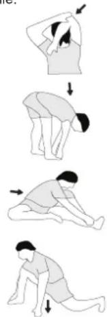
Example - stretching exercises for the warm-up and cool-down phases
Start your warm up by walking on the spot for at least 3 minutes and then perform the following gymnastic exercises to the body for the training phase to prepare accordingly. The exercises do not overdo it and only as far run until a slight drag felt. This position will hold a while.
natural_image
Sequence of four sequential illustrations showing a person performing a stretching or kneeling movement (no text or symbols)Reach with your left hand behind your head to the right shoulder and pull with the right hand slightly to the left elbow. After 20sec. switch arm.
Bend forward as far forward as possible and let your legs almost stretched. Show it with your fingers in the direction of toe. 2 x 20sec.
Sit down with one leg stretched out on the floor and bend forward and try to reach the foot with your hands. 2 x 20sec.
Kneel in a wide lunge forward and support yourself with your hands on the floor. Press the pelvis down. Change after 20 sec leg.
MOTIVATION
The key to a successful program is regular training. You should set a fixed time and place for each day of training and prepare yourself mentally for the training. Only train when you are in the mood for it and always have your goalin view. With continuous training you will be able to see how you are progressing day by day and are approaching your personal training goal bit by bit.
PARTS LIST – SPARE PARTS LIST
Weight approx. [kg]: 25 kg
Load max. (User weight) [kg]: 120 kg
FEATURES
• Water brake resistance
- Upright storable for saving space
• Floor level compensation and transport rollers
- Seat slide with ball bearings
- Incline adjustable computer with LCD display shows: Time, Rower Beats, Beats/Total, approx. calories, distance and optionally pulse frequency.
- Input of limits for time, distance, beats and approx. calories
• Announcement of higher limits
- Integrated holder for smartphones and tablets
- Bluetooth connection for Kinomap APP (IOS and Android)
- Bluetooth connection for optionally pulse belt
NOTE
Please contact us if any components are defective or missing, or if you need any spare parts or replacements in future.
This product is created only for private Home sports activity and not allowed to us in a commercial or professional area. Home Sport use class H/C.
| Illustration No. | Designation Dimension mm Quantity Attached to ET Number | ||||
| 1 Main frame | 1 3+7 33-2461-01-SW | ||||
| 2 Puller unit | cover 1 1+18 33-2461-02-SW | ||||
| 3 Front frame | 1 1+4 33-2461-03-SW | ||||
| 4 Front stabilizer | 1 3 | 33-2461-04-SW | |||
| 5 Seat slide | 2 21 | 33-2461-05-SW | |||
| 6 Rear stabilizer | 1 7 | 33-2461-06-SW | |||
| 7 Slide rail | 2 1+7 33-2461-07-SW | ||||
| 8 Pull rod | 1 79 | 33-2461-08-SW | |||
| 9 Puller support plate | 1 31 | 33-2461-09-SW | |||
| 10 | Cover plate | 1 1 | 33-2461-10-SW | ||
| 11 | Computer adjustment | 1 | 3+12 | 33-2461-11-SW | |
| 12 | Computer holder | 1 | 11+84 | 33-2461-12-SW | |
| 13 | Seat roller axle | 2 5+26 33-2461-13-SI | |||
| 14 | Aluminium edging | 2 7 | 33-2461-14-SI | ||
| 15 | Webbing wheel axle | 3 | 30 | 33-2461-15-SI | |
| 16 | Fixed pin | 8x40 | 1 | 31 | 33-2461-16-SI |
| 17 | Pedal screw | M12x150 | 2 | 1+23 | 39-10331-CR |
| 18 | Top tank half | 1 | 2+19 36-2461-01-BT | ||
| 19 | Bottom tank half | 1 | 18 | 36-2461-02-BT | |
| 20 | Paddle | 1 | 31 | 36-2461-04-BT | |
| 21 | Water tank seal ring | 1 | 18+19 | 36-2461-05-BT | |
| 22 | Pedal left | 1 | 1 | 36-2460-07-BT | |
| 23 | Pedal right | 1 | 1 | 36-2460-08-BT | |
| 24 | Seat | 1 | 5 | 36-2461-14-BT | |
| 25 | Distance tube | 4 13 | 36-2461-15-BT | ||
| 26 | Seat roller | 4 | 13 | 36-2461-09-BT | |
| 27 | Bottom wheel | 2 | 5 | 36-2461-10-BT | |
| 28 | Rubber front foot | 1 | 3 | 36-2461-11-BT | |
| 29 | Handle holder | 1 | 10 | 36-2461-12-BT | |
| 30 | Webbing wheel | 3 | 2 | 36-2461-13-BT | |
| 31 | Puller unit | 1 | 2+9 36-2461-16-BT | ||
| 32 | Front frame top grip | 1 | 3+33 | 36-2461-17-BT | |
| 33 | Front frame bottom grip | 1 | 3+32 | 36-2461-18-BT | |
| 34 | Foot strap | 2 22+23 | 36-2460-37-BT | ||
| 35 | Oval plug small | 2 7 | 36-2461-19-BT | ||
| 36 | Front cap with transport roller left | 1 | 4 | 36-2461-20-BT | |
| 37 | Front cap with transport roller right | 1 | 4 | 36-2461-21-BT | |
| 38 | Rubber end stop | 4 7 | 36-2461-22-BT | ||
| 39 | Rubber foot pad 1 4 | 36-2461-23-BT | |||
| 40 | Rubber insert | 1 | 32+33 | 36-2461-24-BT | |
| Illustration No. | Designation Dimension mm Quantity Attached to ET Number | |||||
| 41 Oval plug | big 2 6 36-2461-25-BT | |||||
| 42 Adjusting | foot pad M8 2 6 36-2461-26-BT | |||||
| 43 Webbing | 1 | 8+31 | 36-2461-27-BT | |||
| 44 | Spring washer non rust | for M8 | 1 | 59 | 39-9864-CR | |
| 45 | Spring washer | for M8 | 10 | 55,56+58 | 39-9864-SW | |
| 46 | Washer non rust | 8//16 | 1 | 59 | 39-9862-CR | |
| 47 | Washer | 8//16 | 10 | 55,56+58 | 39-9862-SW | |
| 48 | Washer | 6//12 | 4 | 61 | 39-10013 | |
| 49 | Washer | 10//20 | 6 | 15 | 39-9989-CR | |
| 50 | Secure ring | C10 | 12 | 13+15 | 36-1826-16-BT | |
| 51 Secure ring | C8 | 2 | 5 36-2461-28-BT | |||
| 52 Cross head screw 4.2x16 | 15 | 31-33,36,39+85 39-9909-SW | ||||
| 53 | Cross head screw | M3x20 | 12 | 18+19 | 39-10528 | |
| 54 | Curved washer | 8//16 | 4 | 56 | 39-10232-SW | |
| 55 | Inner hex screw | M8x40 | 8 | 1+6 | 39-10132 | |
| 56 | Inner hex screw | M8x15 | 8 | 5+7 | 39-9823 | |
| 57 Inner hex screw | M8x60 | 4 3 39-10436 | ||||
| 58 Inner hex screw | M8x45 | 2 4 39-9914-SW | ||||
| 59 | Inner hex screw non rust | M8x20 | 1 | 20 | 39-9823-SW | |
| 60 | Inner hex screw | M6x16 | 4 | 38 | 39-9911 | |
| 61 | Inner hex screw | M6x10 | 14 | 10+13+15 | 36-9805-44-BT | |
| 62 | Inner hex screw | M6x16 | 2 | 29 | 39-9958 | |
| 63 | Inner hex screw | M6x70 | 2 | 11 | 36-9913117-BT | |
| 64 | Inner hex screw | M6x15 | 6 | 76 | 39-10120-SW | |
| 65 Nylon nut | M3 12 | 53 | 39-10126 | |||
| 66 Nylon nut | M6 2 63 | 39-9861-SW | ||||
| 67 Nylon nut | M8 10 | 55+58 | 39-9918-CR | |||
| 68 | Ball bearing | 6000ZZ | 6 | 30 | 39-9998 | |
| 69 Handle foam | 2 | 8 36-2461-29-BT | ||||
| 70 | Shaft sleeve | 4 | 11 | 36-2461-30-BT | ||
| 71 | Upper shaft sleeve | 1 | 31 | 36-2461-31-BT | ||
| 72 Plastic washer | 2 | 31 | 36-2461-32-BT | |||
| 73 | Water tank bushing | 1 | 31 | 36-2461-33-BT | ||
| 74 Rubber washer | 1 | 19 | 36-2461-34-BT | |||
| 75 | Water tank plug | 1 | 18 | 36-2461-35-BT | ||
| 76 | Plastic bearing seat | 1 | 31 | 36-2461-36-BT | ||
| 77 | Cable save | 4 | 3+11 | 36-2461-37-BT | ||
| 78 | Ball bearing | 6904ZZ | 1 | 76 | 36-1506-24-BT | |
| 79 Front blade | 1 | 3 36-2461-38-BT | ||||
| 80 Sensor cable 2 | 81+82 | 36-2461-06-BT | ||||
| 81 | Connection cable | 2 | 80+84 | 36-2461-07-BT | ||
| 82 Sensor holder | 1 | 2 36-1965-11-BT | ||||
| 83 Magnet | 1 | 31 | 36-2461-08-BT | |||
| 84 Computer | 1 | 12 | 36-2461-03-BT | |||
| 85 | Screw | M4x10 | 4 | 84 | 39-9909 | |
| 86 Ten open end wrench | 1 | 36-2461-39-BT | ||||
| 87 | Allen wrench | 5 | 1 | 36-9116-14-BT | ||
| 88 Cross flat wrench | 1 | 36-9107-27-BT | ||||
| 89 Hand water pump | 1 | 36-9107-46-BT | ||||
| 90 Assembly and exercise instruction | 1 | 36-2461-40-BT | ||||

text_image
Image showing a standard ruler with measurement markings and tick marks for measurement reference.0 5 10 15 20 25 30 40 50 60 70 80 90 100
mm
SOMMAIRE
Page Contenu
text_image
Technical diagram of a mechanical assembly with numbered components and directional arrows indicating motion or assembly steps.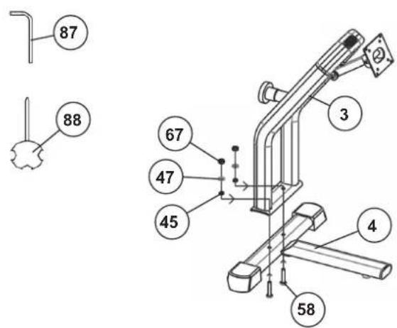
text_image
87 88 67 47 45 3 4 58text_image
Technical diagram of a rowing machine with numbered components and an inset close-up view showing internal parts.text_image
On/Off 75 89 18CONTRÔLE
natural_image
Technical line drawing of a rowing machine with rotating components (no text or symbols)DESCRIPTION DE L'ORDINATEUR
REEMPLACEMENT DES PILES:
natural_image
Diagram of two battery components with no visible text or symbolsCONNECTIVITÉ APP
KINOMAP APP
natural_image
Two black-and-white photos of a man using a rowing machine, showing body posture and motion (no text or symbols visible)NETTOYAGE, ENTRETIEN ET STOCKAGE DE L'EXERCICE
1. Nettoyage
natural_image
Diagram showing a stationary exercise machine transforming from its left-side view to its right-side view (no text or symbols present)CORRECTIONS
natural_image
Isometric line drawing of a mechanical device inside a transparent rectangular frame, labeled with dimensions 1830 and 500 (no text or symbols on the diagram itself)natural_image
Isometric line drawing of a mechanical assembly inside a transparent cube, with dimension labels 2430 and 1700 (no text or symbols on the diagram itself)text_image
Technical diagram of a mechanical assembly with numbered components and directional arrows indicating motion or assembly steps.
text_image
87 88 67 47 45 3 4 58STAP 4
text_image
On/Off 75 89 18CONTROLE
natural_image
Technical line drawing of a rowing machine with levers and wheels (no text or symbols)COMPUTER OMSCHRIJVING
natural_image
Diagram of a battery pack and its internal components (no text or symbols)AAA Batterijen
APP-CONNECTIVITEIT
KINOMAP APP
natural_image
Two black-and-white photos of a man performing rowing exercise on a machine, showing body posture and motion (no text or symbols visible)REINIGING, ONDERHOUD EN OPSLAG
1. Reiniging
natural_image
Diagram showing a stationary exercise machine transforming from its left to its right side, with no text or symbols present.FIXES
Competitie - Zone: Prestaties / Competitie Training
02: Training hartslagberekening
natural_image
Sequence of four sequential illustrations showing a person performing a stretching or kneeling movement (no text or symbols)text_image
Image showing a ruler with measurement markings and tick marks for scale0 5 10 15 20 25 30 40 50 60 70 80 90 100
mm
OBSAH
Strana Obsah
text_image
Technical diagram of a mechanical assembly with numbered components and directional arrows indicating motion or assembly steps.text_image
On/Off 75 89 18KONTROLA
natural_image
Technical line drawing of a rowing machine with levers and wheels (no text or symbols)POPIS POČÍTAČE
natural_image
Diagram of a battery pack and its internal components, showing battery housing and casing (no text or symbols)KONEKTIVITA
KINOMAP APP
natural_image
Two black-and-white photos of a man performing rowing exercise on a machine, showing body posture and motion (no text or symbols visible)ČIŠTĚNÍ, ÚDRŽBA A SKLADOVÁNÍ
1. Čištění
natural_image
Diagram showing a rowing machine before and after assembly, with no visible text or symbolsŘEŠENÍ POTÍŽÍ
natural_image
Sequence of four sequential illustrations showing a person performing a stretching or kneeling movement (no text or symbols)text_image
Image showing a ruler with measurement markings and tick marks for scale0 5 10 15 20 25 30 40 50 60 70 80 90 100
mm

EN IEC 61000-6-3:2021
EN IEC 61000-6-1:2019
EN ISO 20957-1:2013
EN ISO 20957-7:2021
EC-DECLARATION OF CONFORMITY
declares, in our sole responsibility, that the products:
Article:
GARDA Art.-No. 2461
Product description:
Rowing machine – stationary training equipment
comply with the following essential requirements of the following EU directives
2014/53/EU (RED) Radio Equipment Directive
2011/65/EU (RoHS) Restriction of Hazardous Substances
and additionally standards, guidelines and regulations:
EN 301 489-1 V2.2.3:2019
EN 301 489-17 V3.2.4:2020
EN 300 328 V2.2.2 :2019
EN 62479:2010
EN 50663:2017
EN 62368-1:2014+A11:2017
EN IEC 61000-6-3:2021
EN IEC 61000-6-1:2019
EN ISO 20957-1:2013
EN ISO 20957-7:2021
text_image
Exploded view diagram of a mechanical assembly with numbered components for identification© by Top-Sports Gilles GmbH D-42551 Velbert (Germany)