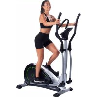
AX 7000 - Elliptical bike Christopeit - Free user manual and instructions
Find the device manual for free AX 7000 Christopeit in PDF.

| Product type | Elliptical trainer |
| Brand | Christopeit |
| Model | AX 7000 |
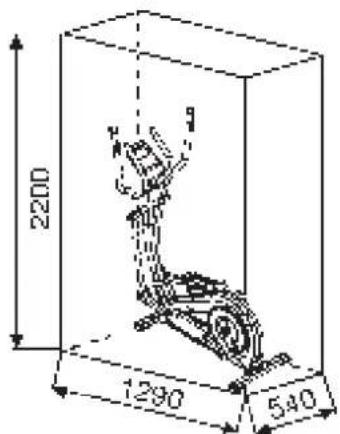
| Dimensions (L x W x H) | 120 x 60 x 163 cm |
| Product weight | 40 kg |
| Maximum user weight | 150 kg |
| Power supply | 6V DC / 1 A power adapter (230V~ / 50Hz) |
| Flywheel weight | Approx. 8 kg |
| Resistance | 24 levels, motorized adjustment |
| Training programs | Manual, 10 fitness, 5 customizable (U1-U5), 1 watt (30-350 W), 4 heart rate programs (55%, 75%, 95% of max HR and free target) |
| Display | Digital display: time, speed, distance, calories, heart rate, watts, recovery |
| Heart rate measurement | Contact sensors on fixed handlebar |
| Pedal adjustment | 3 positions (adjustable foot shells) |
| Recovery function (Fitness Test) | Yes, rating from F1.0 to F6.0 |
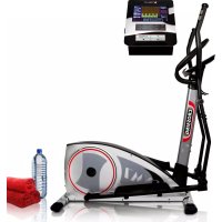
| Smartphone/tablet compatibility | Built-in holder |
| Transport | Transport wheels on front foot |
| Stability | Height-adjustable rear feet (compensates for unevenness) |
| Classification | Domestic use (class HA according to EN ISO 20957-1 and -9) |
| Assembly time | Approx. 50 minutes |
| Maintenance | Clean with damp cloth; check screws every 50 h; lubricate axles every 100 h |
| Spare parts | Available at www.christopeit-service.de (order ref. 1908) |
Frequently Asked Questions - AX 7000 Christopeit
User questions about AX 7000 Christopeit
0 question about this device. Answer the ones you know or ask your own.
Ask a new question about this device
Download the instructions for your Elliptical bike in PDF format for free! Find your manual AX 7000 - Christopeit and take your electronic device back in hand. On this page are published all the documents necessary for the use of your device. AX 7000 by Christopeit.
USER MANUAL AX 7000 Christopeit
natural_image
Woman exercising on an outdoor fitness machine (no text or symbols visible)D
Assembly and exercise instructions for Order No. 1908
F
NL
Schritt 2:
natural_image
Three-step line drawing of a woman performing an exercise on an easotop bike (no text or symbols)Programm 5 Berg
Programm 6 Intervall Programm 7 Cardio Programm 8 Plateau
Programm 9 Treppe Programm 10 Rally

User Setting Program 11 (U1) User Setting Program 12 (U2) User Setting Program 13 (U3)


User Setting Program 14 (U4) User Setting Program 15 (U5)

Programm 16 Watt Control Program Programm 17 HRC (55%)
Programm 18 HRC (75%)

Programm 19 HRC (95%)

Programm 20 HRC
Programm Manual:
Programme 1 - 10: Fitness
line
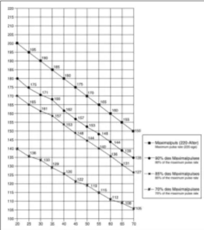
| X-Axis | Maximalpuls (220-After) Maximum pulse rate (200-ages) | 80% des Maximalpulses 80% of the maximum pulse rate | 85% des Maximalpulses 85% of the maximum pulse rate | 70% des Maximalpulses 70% of the maximum pulse rate | |---|---|---|---|---| | 20 | 200 | 195 | 190 | 180 | | 25 | 195 | 190 | 185 | 175 | | 30 | 190 | 185 | 180 | 171 | | 35 | 185 | 180 | 175 | 166 | | 40 | 180 | 175 | 170 | 162 | | 45 | 175 | 170 | 165 | 157 | | 50 | 170 | 165 | 160 | 153 | | 55 | 165 | 160 | 155 | 148 | | 60 | 160 | 155 | 150 | 144 | | 65 | 155 | 150 | 145 | 140 | | 70 | 150 | 145 | 140 | 136 | | 20-70 | 140 | - | - | - | | 25-70 | - | - | - | - | | 30-70 | - | - | - | - | | 35-70 | - | - | - | - | | 40-70 | - | - | - | - | | 45-70 | - | - | - | - | | 50-70 | - | - | - | - | | 55-70 | - | - | - | - | | 60-70 | - | - | - | - | | 65-70 | - | - | - | - | | 70-70 | - | - | - | - | The chart displays a single data series with values labeled on each line. The x-axis ranges from '20' to '70', and the y-axis ranges from '100' to '220'. The legend indicates four distinct pulse rate thresholds: 'Maximalpuls (220-After)' and '80% des Maximalpulses'. The chart is annotated with the number above each data point.Berechnungsformeln: Maximalpuls = 220 - Alter
90% des Maximalpuls = (220 - Alter) x 0,9
85% des Maximalpuls = (220 - Alter) x 0,85
70% des Maximalpuls = (220 - Alter) x 0,7
natural_image
Simple line drawing of a person in a kneeling pose (no text or symbols)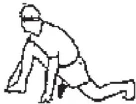
natural_image
Simple line drawing of a person in a kneeling or stretching pose (no text or symbols)| 1. | Important | Recommendations | and |
| 2. | Assembly | Instructions | With |
| Mount, use | and | dismount | |
| 3. | Watt table | Page | 21 |
| 4. | Computer instructions-trouble shooting | ||
| Cleaning, Check and Storage | |||
| 5. | Training Instructions-Warm-up | ||
| 6. | Parts List-List of spare | ||
| 2. | Summary of Parts Page | ||
Dear customer,
We congratulate your purchase of the home training sports unit and hope that we will have great deep pleasure with it. Please take heed of the enclosed notes and instructions and follow them closely concerning assembly and use.
Please do not hesitate to contact us at any time if you should have any questions. Page 22 - 24
Important Recommendations and Safety Instructions
Our products are all tested and therefore represent the highest current safety standards. However, this fact does not make it unnecessary to observe the following principles strictly.
-
Assembly the machine exactly as described in the installation instructions and use only the enclosed, specific parts of the machine. Before assembling, verify the completeness of the delivery against the delivery notice and the completeness of the carton against the assembly steps in the installation and operating instructions.
-
Check the firm seating off all screws, nuts and other connections before using the machine for the first time and at regular intervals to ensure that the trainer is in a safe condition.
-
Set up the machine in a dry, level place and protect it from moisture and water. Uneven parts of the floor must be compensated by suitable measures and by the provided adjustable parts of the machine if such are installed. Ensure that no contact occurs with moisture or water.
-
Place a suitable base (e.g. rubber mat, wooden board etc.) beneath the machine if the area of the machine must be specially protected against indentations, dirt etc.
-
Before beginning training, remove all objects within a radius of 2 metres from the machine.
-
Do not use aggressive cleaning agents to clean the machine and employ only the supplied tools or suitable tools of your own to assemble the machine and for any necessary repairs. Remove drops of sweat from the machine immediately after finishing training.
-
WARNING! Systems of the heart frequency supervision can be inexact. Excessive training can lead to serious health damage or to the death. Consult a doctor before beginning a planned training programme. He can define the maximum exertion (pulse, Watts, duration of training etc.) to which you may expose yourself and can give you precise information on the correct posture during training, the targets of your training and your diet. Never train after eating large meals.
This item is not suitable for therapeutically purposes!
-
Only train on the machine when it is in correct working order. Use original spare parts only for any necessary repairs. WARNING: Replace the worm parts immediately and keep this equipment out of use until repaired.
-
When setting the adjustable parts, observe the correct position and the marked, maximum setting positions and ensure that the newly adjusted position is correctly secured.
-
Unless otherwise described in the instructions, the machine must only be used for training by one person at a time. The exercise time should not overtake 60 min/daily.
-
Wear training clothes and shoes which are suitable for fitness training with the machine. Your clothes must be such that they cannot catch during training due to their shape (e.g. length). Your training shoes should be appropriate for the trainer, must support your feet firmly and must have non-slip soles.
-
WARNING! If you notice a feeling of dizziness, sickness, chest pain or other abnormal symptoms, stop training and consult a doctor.
-
P Never forget that sports machines are not toys. This appliance can be used by children aged from 8 years and above and persons with reduced physical, sensory or mental capabilities or lack of experience and knowledge if they have been given supervision or instruction concerning use of the appliance in a safe way and
understand the hazards involved. Children shall not play with the appliance. Cleaning and user maintenance shall not make by children without supervision. Take suitable measures to ensure that children never use the machine without supervision.
-
The appliance use only to be used with the power supply unit provided with the appliance.
-
Ensure that the person conducting training and other people never move or hold any parts of their body into the vicinity of moving parts.
-
At the end of its life span this product is not allowed to dispose over the normal household waste, but it must be given to an assembly point for the recycling of electric and electronic components. You may find the symbol on the product, on the instructions or on the packing.
The materials are reusable in accordance with their marking. With the re-use, the material utilization or the protection of our environment. Please ask the local administration for the responsible disposal place.
-
To protect the environment, do not dispose of the packaging materials, used batteries or parts of the machine as household waste. Put these in the appropriate collection bins or bring them to a suitable collection point.
-
For speed dependent operation mode, the braking resistance level can be adjustable manually and the variations of power will depend on the pedaling speed. For speed independent operation mode, the user can set the wanted power consumption level in Watt, constant power level will be kept by various braking resistance levels, that will be determined automatically by system. That is independent on the pedaling speed.
-
The unit has a resistance device with 32 levels. This makes it possible to increase or reduce the braking resistance and thus the amount of effort required in the training. Pressing the button „-“ reduces the braking resistance and thus the amount of effort required in the training. Pressing the button „+“ increases the braking resistance and thus the amount of effort required in the training.
-
This machine has been tested and certified in compliance with DIN EN ISO 20957-1/2014 and EN ISO 20957-9:2016 "H,A". The maximum permissible load (=body weight) is specified as 150 kg. The classification of HA means this exercise bike is designed foe home use only and with good accuracy class, the variations of power consuming are within ±5W up to 50W and ±10% over 50W. This item's computer corresponds to the basic demands of the EMV Directive of 2014/30/EU.
-
The assembly and operating instructions is part of the product. If selling or passing to another person the documentation must be provided with the product.
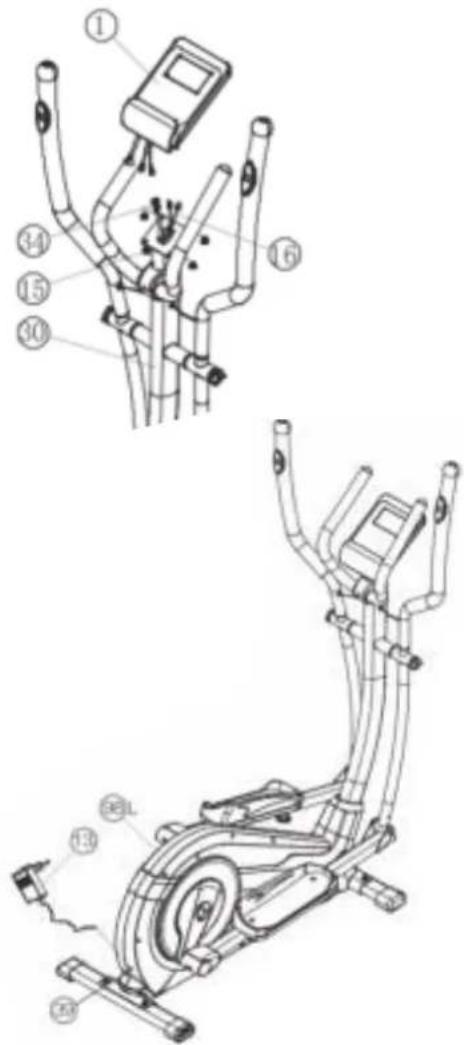
Assembly Instructions
Remove all the separate parts from the packaging, lay them on the floor and check roughly that all are there on the base of the assembly steps. Please note that a number of parts are connected directly to the main frame preassembled. In addition, there are several other individual parts that have been attached to separate units. This will make assembly easier and quicker for you. Assembly time: 50 min.
Step 1:
Attach the stabilizer (56+58).
- Attach the front stabilizer (56) assembled with front caps with transportation roller (55) to main frame (40) by using bolts M8x45 (59), washers (37), spring washers (32) and cap nuts (36).
- Attach the rear stabilizer (58) assembled with height adjustable caps (57) to main frame (40) by using bolts (59), washers (37), spring washers (32) and cap nuts (36). (For uneven floor, you can adjust the height at rear caps (57) and secure for stable position.)
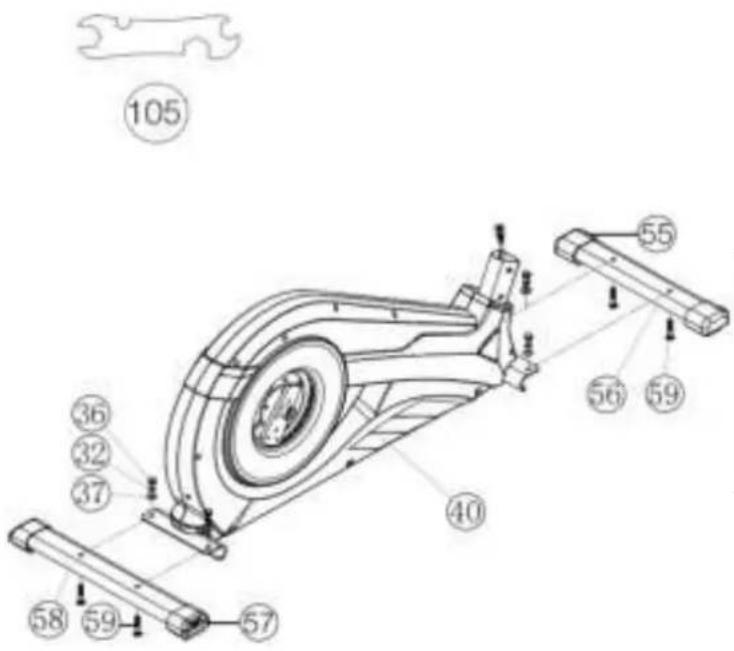
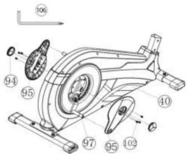
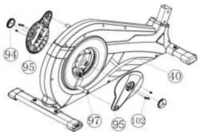
Step 2:
Assembly of pedal cranks (97) and crank covers (95).
- Put the pedal crank (97) at pedal crank holder (93) so that the holes align and screw it tightly by using screw M8x20 (96) and spring washers (32).
- Put the crank cover (95) onto the pedal crank (97) and attach it by using screws M5x15 (102).
- Attach the crank plug (94) at crank cover (95).

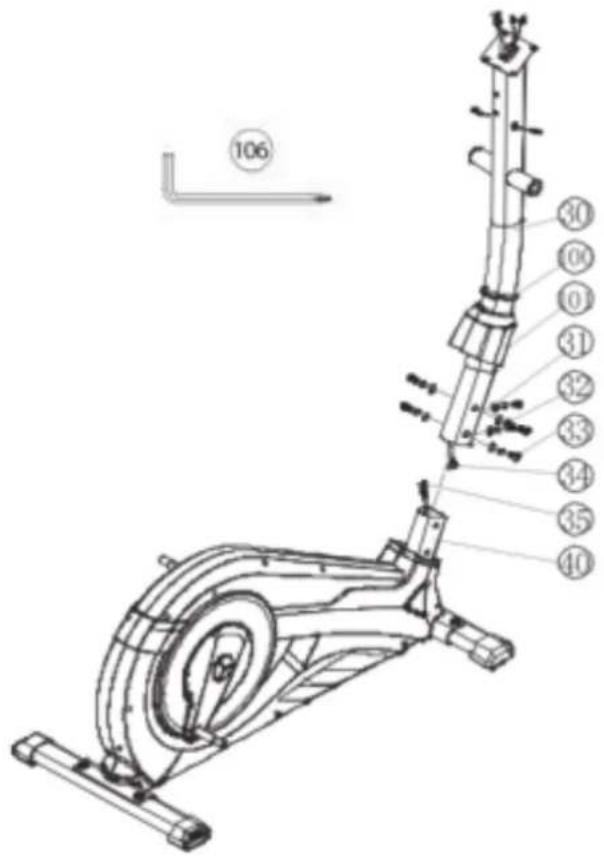
Step 3: Assembling of the connection cable (34) to the motor cable (35) and installation of support (30) at the main frame (40).
- Place screws M8x20 (33), curved washers (31) and spring washers (32) accessibly beside the front part of the main frame (40).
- Place the lower end of the support (30) against the main frame (40) and push the rubber ring (100) and support cover (101) onto the support (30).
- Plug the ends of the two computer cable harnesses (34+35) projecting from (30+40) together. (Note: The computer cable harness (34) projecting from the support (30) must not slide into the tube, as it is required for later steps of installation.) When joining the tubes, ensure that the cable connection will not trapped.
- Put one spring washer (32) and one curved washer (31) on each screw (33). Push the screws (33) through the holes in the support (30), screw into the threaded holes of the main frame (40) and tighten lightly.
- Push the plastic cover (101) and rubber ring (100) into the right position to cover the connection point.
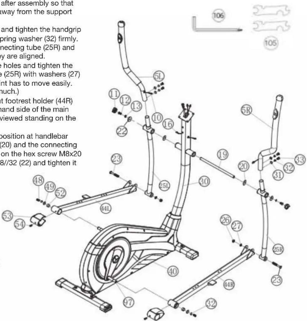
Step 4: Installation of handgrips (5), footrest holder (44) and connecting tubes (25).
- Push the handgrip bars (5R) onto the connecting tubes (25R) and adjust the holes in the tubes so that they are aligned.
(Note: the handgrip bars must be aligned after assembly so that the upper ends are inclined outwards (away from the support (30)). - Push the screws (33) through the holes and tighten the handgrip bars (5) with curved washers (31) and spring washer (32) firmly.
- Put the footrest holder (44R) at the connecting tube (25R) and adjust the holes in the tubes so that they are aligned.
- Push the screw M8x78 (23) through the holes and tighten the footrest holder (44R) at connection tube (25R) with washers (27) and nut (26) firmly. (This connection point has to move easily. So please don't tighten the screw too much.)
- Place the preassembled unit of the right footrest holder (44R) and connecting tube (25R) at the right hand side of the main frame (40). (Note: Right is specified as viewed standing on the machine during training.)
-
Push the grip axle (19) into the middle position at handlebar support (30) and put one wave washer (20) and the connecting tube (25R) onto the axles' end (19). Put on the hex screw M8x20 (12) a spring washer (32) and a washer 8//32 (22) and tighten it firmly.
-
Put the foot pedal holder (44R) at the pedal crank (97) and tighten them with steel tube (52), washer 8//20 (49), spring washer (32) and screw M8x20 (48) firmly.
-
Install the left footrest holder (44L) incl. all additionally required parts on the left hand side of the machine as described in 1.-7.
-
Put the plugs of pulse cables (10) into the plugs from pulse connection cables (16) and attach the screw caps (11) onto screws (12).
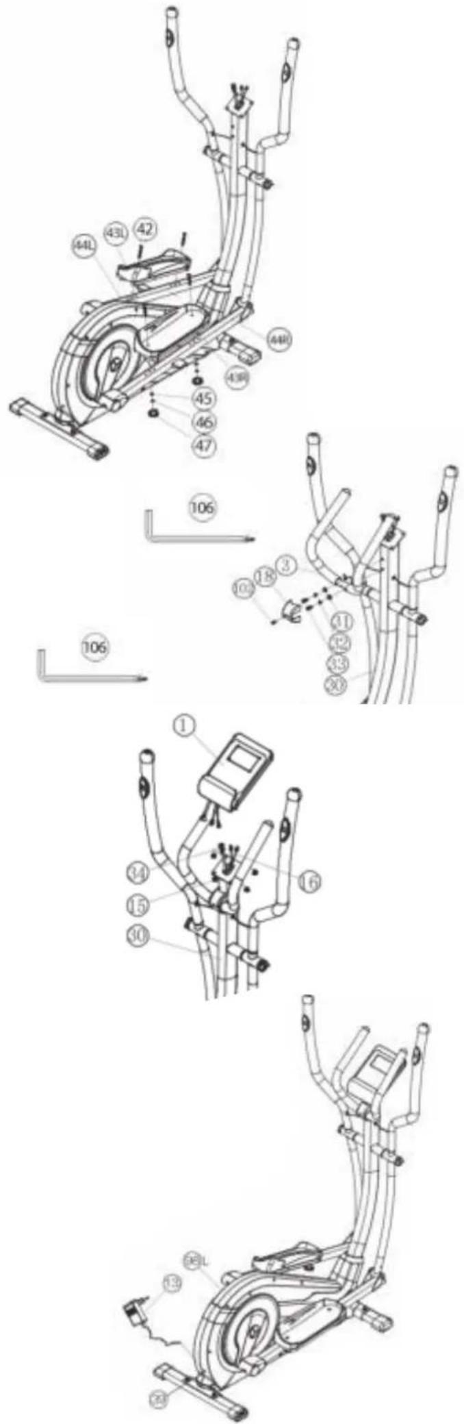
Step 5: Installation of the footrests (43) at footrest holder (44).
- Push the right footrest (43R) onto the footrest holder (44R). Adjust the holes in the parts so that they are aligned.
- Push the screws M6x50 (42) from above through the holes. Push from the opposite side on a washer (45) and spring washer (46), screw on a handgrip nut (47) and tighten firmly.
- Install the left footrest (43L) on the left footrest holder (44L) as described in 1. - 2. (Note: The position adjusted in this way should always be equal at both sides. The right and left footrests can be discerned by the edges of the longitudinal sides of the footrests. The high edges of the footrests (43) must point inwards (towards the main frame.) The positions can change as desired at all times by removing the carriage bolts (42) and sliding the footrests on the footrest brackets to get a comfortable exercise position close to the hand grip.)
Step 6: Attach the handle grip (3) at support (30).
- Push a spring washer (32) and a washer (31) onto each screw M8x20 (33).
- Place the handle grip (3) against the holder at support (30) and tighten the handle grip (3) at handlebar support (30) firmly.
- Attach the grip cover (18) at handle grip (3) and secure with screw M5x15 (102).
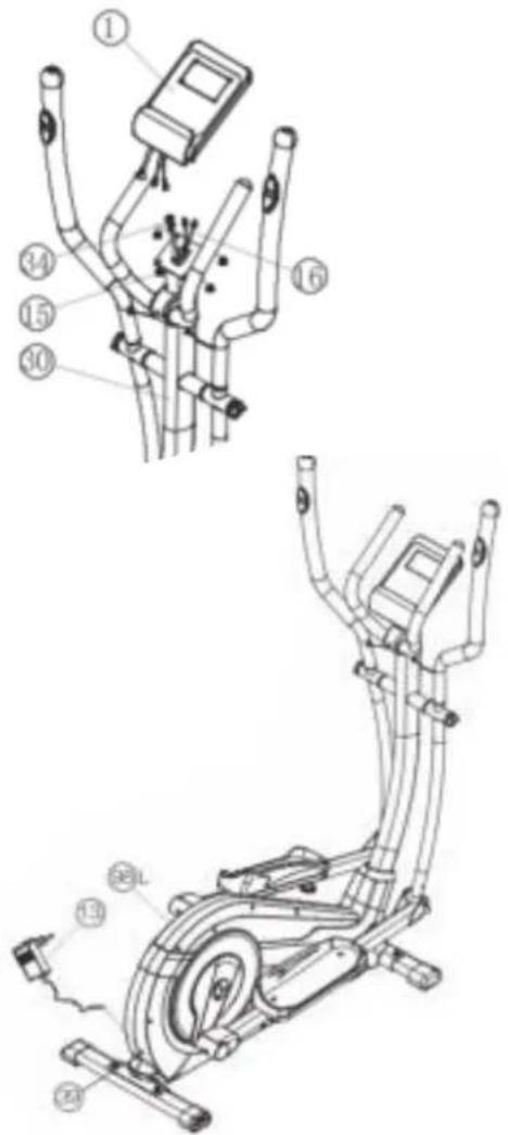
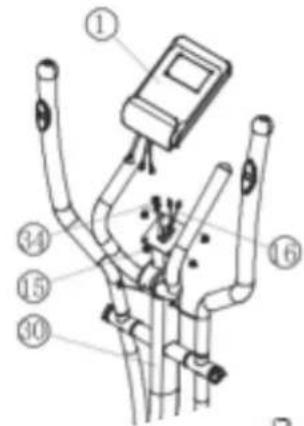
Step 7: Attach the computer (1) at support (30).
- Put the plug of connection cable (34) into the plug from computer (1) backside.
- Insert the plug of pulse connection cables (16) to the jack of the computer (1) and attach the computer (1) to top monitor bracket of front post (30) with screws M5x10 (15). (Attention: Ensure that the cable loom are not crunched or pinched during installation.)
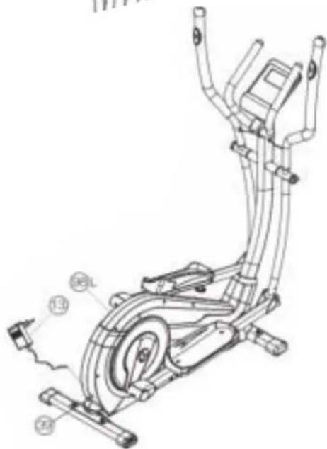
Step 8: Attach the power.
- Please insert the plug of adaptor (13) to the power plug (39) at end of chain guard (98).
- Please insert the plug of adaptor (13) to the jack of wall power (230V\~50Hz).
Step 9: Checks
- Check the correct installation and function of all screwed and plug connections. Installation is thereby complete.
- When everything is in order, familiarize yourself with the machine at a low resistance setting and make your individual adjustments.
Note: Please keep the tool set and the instructions in a safe place as these may be required for repairs or spare parts orders becoming necessary later.
natural_image
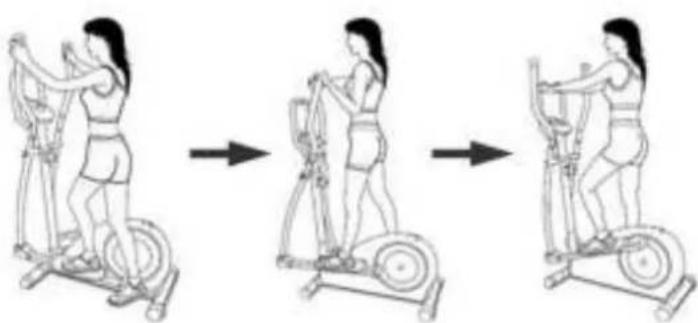
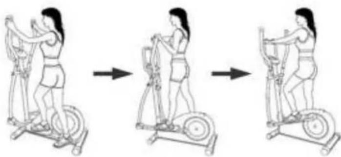
Three-step line drawing of a woman performing an exercise on an easotop bike (no text or symbols)Mount, Use & Dismount
Transportation of Equipment:
There are two rollers equipped on the front foot. For moving, you can lift up the rear foot and drive it to where you would like to locate or store it. (Attention: If this item hasn't got a fixed handlebar, please use carefully the left and right arms for procedure.)
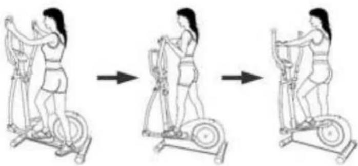
Mount, Use & Dismount
Mount:
a. Stand beside the item, put the nearest footrest into deepest position and hold the fixed handlebar tightly.
b. Put your foot onto the footrest, try to put whole body weight on your foot and simultaneously cross over
with your another foot on the other side footrest and place there on the footrest too.
c. Now you are in the position to start your training.
Use:
a. Keep your hands in desired position on the fixed handlebar.
b. Pedal your exercise item by step your feet on footrests and balance the body weight to left and right side of footrest
c. If you like to exercise the upper body too, you can place the hands from fixed handle bar to the left and right handle grips.
d. Then you can increase the pedaling speed gradually and adjust braking resistance levels to increase the exercise intension.
e. Keep always your hands on fixed handle bar or hand grips left and right.
Dismount:
a. Slow down the pedaling speed until it comes to rest.
b. Keep the hands grabbing the fixed handlebar tightly, put one foot cross over the equipment and land on the floor, then land the other one.
This training equipment is a stationary exercise machine used to simulate a combination of biking, stepping and walking without
causing excessive pressure to the joints, hence decreasing the risk of impact injuries.
Exercise this item offers a non-impact cardiovascular workout that can vary from light to high intensity based on the resistance preference set by the user. It will strengthen your muscles of upper and lower body and increase cardio capacity and maintain fitness of your body also.
Training area in mm
(for home trainer and user)
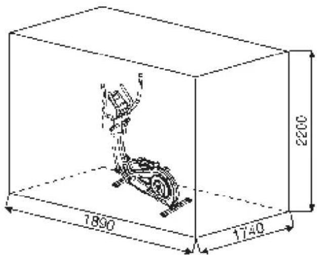
Free area in mm
(Training area and security area
(rotating 60cm))
| LEVEL 20RPMWATT | 30RPMWATT | 40RPMWATT | 50RPMWATT | 60RPMWATT | 70RPMWATT | 80RPMWATT | |
| 1 | 7 15 19 | 33 40 43 61 | |||||
| 2 | 9 18 24 | 40 50 55 76 | |||||
| 3 | 10 20 29 | 46 60 67 90 | |||||
| 4 | 11 22 34 | 54 70 82 107 | |||||
| 5 | 12 25 39 | 61 80 93 125 | |||||
| 6 | 14 27 44 | 68 90 106 140 | |||||
| 7 | 15 30 49 | 74 100 118 155 | |||||
| 8 | 16 33 53 | 81 110 130 171 | |||||
| 9 | 18 36 59 | 88 120 143 186 | |||||
| 10 | 19 38 64 | 95 130 155 202 | |||||
| 11 | 20 41 69 | 103 140 167 218 | |||||
| 12 | 22 43 73 | 110 150 180 232 | |||||
| 13 | 23 46 79 | 117 160 191 250 | |||||
| 14 | 24 49 84 | 124 170 205 268 | |||||
| 15 | 26 52 89 | 132 180 220 286 | |||||
| 16 | 27 55 94 | 140 190 235 304 | |||||
| 17 | 28 58 99 | 149 200 251 323 | |||||
| 18 | 30 62 104 | 157 210 267 342 | |||||
| 19 | 31 65 109 | 164 220 279 356 | |||||
| 20 | 32 68 114 | 172 230 290 370 | |||||
| 21 | 34 71 120 | 179 240 301 388 | |||||
| 22 | 35 74 127 | 186 250 314 406 | |||||
| 23 | 36 77 133 | 193 260 330 420 | |||||
| 24 | 38 80 139 | 201 270 345 438 | |||||
Remarks:
- The power consumptions (Watt) are adjusted by measuring the driving speed (min-1) of axle and the braking torque (Nm).
- Your equipment was tested to fulfill the requirements of its accuracy classification before shipment, If you have doubts about the accuracy, please contact with your local retailer or send it to accredited test laboratory to ensure or calibrate it.
(Please note that a deviation tolerance as noted on page 15, is permissible.)
Computer Instructions
The monitor is designed for programmable magnetic bikes and introduced with the following categories:
- Key Functions
- About Displays
- Operating Ranges
- Things You Should Know Before Exercising
- Operation Instructions
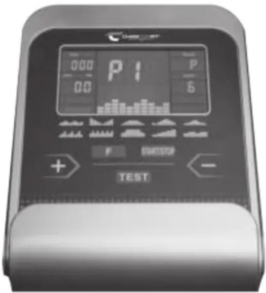
• Key Functions
There are total 5 keys including START/STOP, FUNCTION(F), UP(+), DOWN(-), and RECOVERY (TEST).
START/STOP: Starts or stops the program chosen. And, resets the monitor by pressing and holding for 2 seconds.
FUNCTION (F): Chooses or enters the functions from PROGRAMS, TIME, DISTANCE, WATT, CAL, TARGET HEART RATE, AGE, and 10 columns. The chosen function shall flash. Please note that not all the functions can be selected in every program according to the types of each program. During exercise, press the F-key to display the functions RPM, watts and calories or speed, time and distance permanently or alternately.
UP(+): Selects or increases the values of PROGRAMS, TIME, DISTANCE, WATT, CAL., TARGET HEART RATE, AGE, and 10 columns.
DOWN(-): Selects or decreases the values of PROGRAMS, TIME, DISTANCE, WATT, CAL., TARGET HEART RATE, AGE, and 10 columns.
RECOVERY(TEST): Starts the function of PULSE RECOVERY.
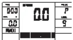
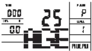
- About Display
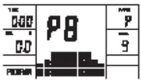
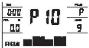
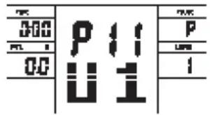
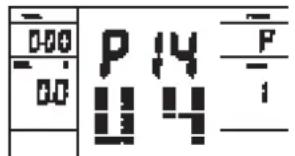
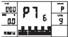
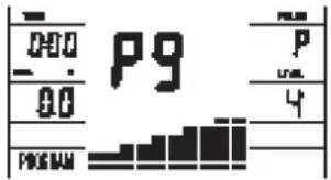
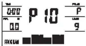
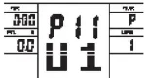
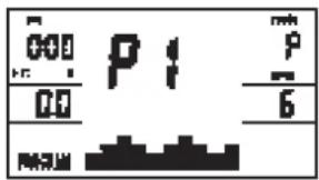
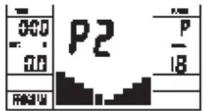
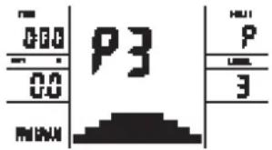
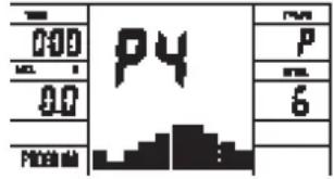
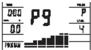
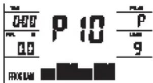
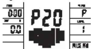
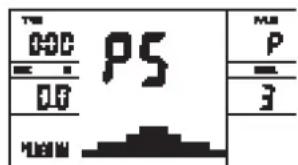
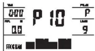
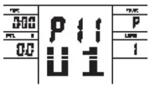
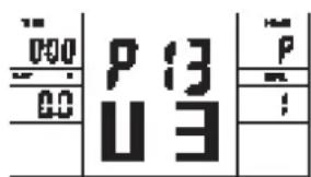
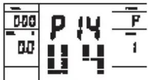
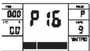
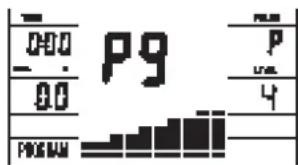
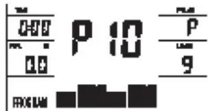
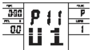
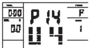
PROGRAM:
Indicates the programs selected from PROGRAM 1 to PROGRAM 20
LEVEL:
Indicates the level of loading selected from LEVEL 1 to LEVEL 24.
TIME/ WATT :
Indicates Time or Watt alternately. The time shows minutes and seconds. If preset, time counts downwards. Minimum preset 5Min. Range 5-99Min. The actually power display show in Watt. Preset range 30-350Watt only in Watt program P16.v Or permanently by pressing the F-key.
RPM/SPEED/KMH:
Indicates RPM or Speed alternately. The RPM display shows the cycle turnings per minute. The speed display show kilometers per hour. Or permanently by pressing the F-key.
DIST/CAL:
Indicates Distance or Calorie alternately.
The distance display show kilometer. Preset range 1-999km. If preset distance counts downwards. The calories display shows kcal. Minimum preset 10kcal. Preset range 10-990. Or permanently by pressing the F-key.
PULSE :
Indicates the actually pulse heart rate. The whole set of heart rate detector include 2 sensors each side. Each sensor has 2 pieces of metal parts. The correct way to get detected is to gently hold both metal parts each hand. With the good signals picked up by the computer, the heart mark in the HEART RATE Display shall flash. Range 60-240bpm. If a pulse upper limit is specified, the display flashes when the preset value is reached.
TARGET H.R.:
Indicates only one value of TARGET HEART RATE.
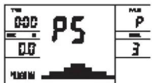
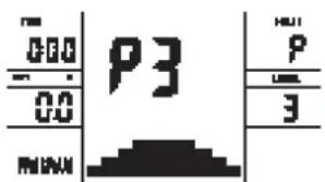
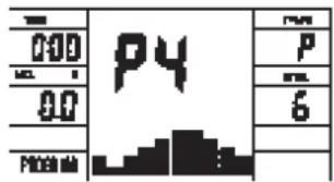
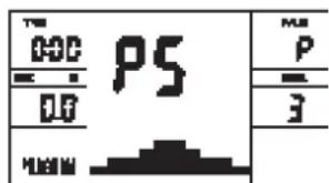
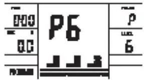
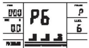
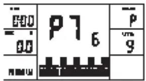
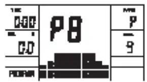
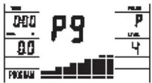
LOADING Profiles:
There are 10 columns of loading bars, and 8 bars in each column. Each column represents 1 minute workout (without the change of TIME value), and each bar represents 3 levels of loading.
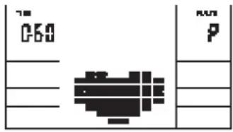
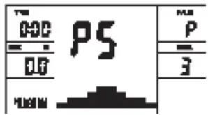
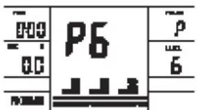
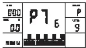
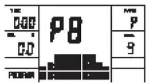
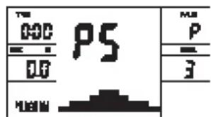
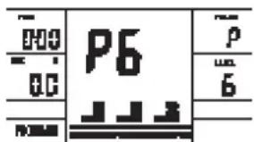
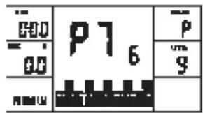
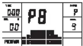
Program Graph:
Each graph shown is the profile of the loading in each interval (column). With the value of TIME counting up, each interval is 3 minute that all the columns make up 30 minutes. With the value of TIME counting down, each interval is the value of setup TIME divided by 10. For example, if the time value is setup to 40 minutes, each interval will be 40 minutes divided by 10 intervals (40/10=4). Then, each interval will be 4 minutes. The following graphs are all the profiles in the monitor.
bar
| Category | Value | |---|---| | 1 | 2 | | 2 | 2 | | 3 | 3 | | 4 | 3 | | 5 | 4 | | 6 | 4 | | 7 | 5 | | 8 | 6 | | 9 | 7 | | 10 | 8 | | 11 | 9 | | 12 | 10 |- Things You Should Know Before Exercising
The values calculated or measured by the computer are for exercise purpose only, not for medical purpose.
Programs Selection:
There are 22 programs 1 Manual Program, 10 Preset Programs, 4 Heart Rate Control Programs, 5 User Setting Programs, 1 Speed Independent Watt-Program, and 1 Pulse Recovery Measuring.
Manual Program Programm 1 Rolling Program 2 Valley
Programm 3 Fatburn Programm 4 Ramp Programm 5 Mountain
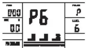
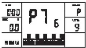
Programm 6 Interval Programm 7 Cardio Programm 8 Endurance

Programm 9 Slope Programm 10 Rally
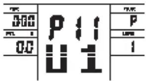
User Setting Program 11 (U1)
User Setting Program 12 (U2)
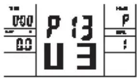
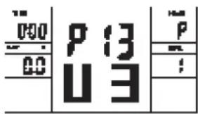
User Setting Program 13 (U3)

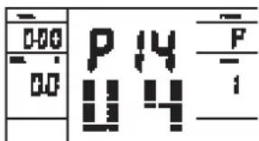
User Setting Program 14 (U4) User Setting Program 15 (U5)


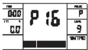
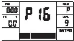
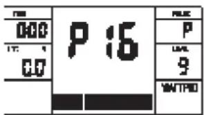
Programm 16 Watt Control Program
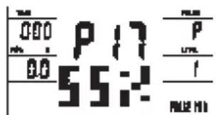
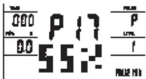
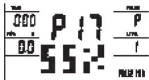
Programm 17 HRC (55%)
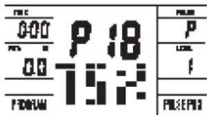
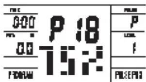
Programm 18 HRC (75%)
Programm 19 HRC (95%)

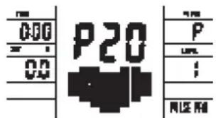
Programm 20 HRC

• Operation Instructions
MANUAL Program:
PROGRAM MANUAL is a manual program. Press „F“ key to select TIME, DISTANCE or CAL.. Then, press (+) or (-) key to adjust the values. The default level of loading is 6.
After pressing „START/STOP“ key to exercise, please also apply the heart rate detector appropriately. Users may exercise in any desire level (by pressing (+) or (-) during the workout) with a period of time or a certain distance.
Exercising with a specific Goal:
TIME Control: Sets up a period of time to exercise. (5-99Min.)
DISTANCE Control: Sets up a certain distance to exercise. (1-999km)
CALORIE Control: Sets up certain calories to exercise. (10-990kcal)
Set exercise parameters with F-key for Time/Distance/Calories and Pulse.
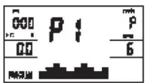
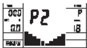
Preset Programs P1-P10:
PROGRAM 1 to PROGRAM 10 are the preset programs. Press „F“ key to select TIME, DISTANCE or CAL. Then, press (+) or (-) key to adjust the values. Users may exercise with different level of loading in different intervals as the profiles show. After pressing „START/STOP“ key to exercise, please also apply the heart rate detector appropriately. Users may also exercise in any desire level (by pressing (+) or (-) during the workout) with a period of time or a certain distance. Set exercise parameters with F-key for Time/Distance/Calories and Pulse.
User Setting Programs P11-P15:
Program 11 to Program 15 are the user-setting programs. Users are free to edit the values in the order of TIME, DISTANCE, CAL. and the level of loading in 10 intervals.
The values and profiles will be stored in the memory after setup. After pressing „START/STOP“ key to exercise, please also apply the heart rate detector appropriately. Users may also change the ongoing loading in each interval by pressing (+) or (-) key, and they will not change the level of loading stored in the memory. With the input of age, the computer may suggest a target heart rate to exercise. The suggested heart rate is 80% (220 – age). So, if the heart rate detected equals to or greater than the TARGET H.R., the value of HEART RATE will keep flashing. Please note that it is a warning for users to speed down or to lower the level of loading. Set exercise parameters with F-key for Time/Distance/Calories and Pulse.
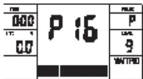
Speed Independent Watt-Program P16:
Program 16 is a Speed Independent Program. Press „F“ key to select the values of TIME, DISTANCE, CAL. and WATT.
Then, press (+) or (-) key to adjust the values. After pressing „START/STOP“ key to exercise, please also apply the heart rate detector appropriately. During the exercise, the level of loading is not adjustable. In this program, computer will adjust the level of loading according to the value of WATT setup.
For example, the level of loading may increase while the speed is too slow. Also, the level of loading may decrease while the speed is too fast. As a result, the calculated value of WATT will close to the value of WATT setup by users. Set exercise parameters with F-key for Time/Distance/Calories and Pulse.
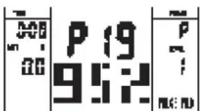
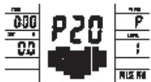
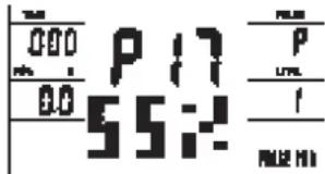
Heart Rate Control Programs P17-P20:
Program 17 to Program 20 are the Heart Rate Control Programs. In Program 17 to Program 19, press „F“ key to select TIME, DISTANCE, CAL. and AGE. Then, press (+) or (-) key to adjust the values. Users may exercise in a period of time or a certain distance with 55% Max Heart Rate in Program 17, 75%
Max Heart Rate in Program 18, and 95% Max Heart Rate in Program 19. After pressing „START/STOP“ key to exercise, please also apply the heart rate detector appropriately. In these programs, the computer will adjust the level of loading according to the heart rate detected. For example, the level of loading may increase while the heart rate detected is lower than TARGET H.R. Also, the level of loading may decrease while the heart rate detected is higher than TARGET H.R. As a result, the user's heart rate will be adjusted to close the TARGET H.R. in the range of TARGET H.R. -5 and TARGET H.R. +5. With the input of age, the computer may suggest a target heart rate to exercise. The suggested heart rate is 80% (220 - age).
So, if the heart rate detected equals to or greater than the TARGET H.R., the value of HEART RATE will keep flashing. Please note that it is a warning for users to slow down or to lower the level of loading.
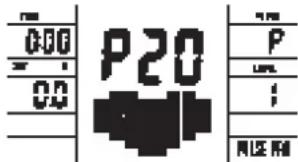
In program 20, press „F“ key to select TIME, DISTANCE, CAL. and TARGET H.R. Users may setup a target heart rate to exercise in a period of time or a certain distance.
TEST-Pulse Recovery:
It is a function to check the condition of pulse recovery that is scaled from 1.0 to 6.0 while 1.0 means the best and 6.0 means the worst and the increment is 0.1. In order to get rated correctly, users must test it right after the workout finished by pressing „TEST“ key and then stop exercising. After the key is pressed, please also apply the heart rate detector appropriately. The test will last for 1 minute and the result will show in the display.
Cleaning, Checks and Storage of the Ergometer bike:
1. Cleaning
Use only a less wet cloth for cleaning. Caution: Never use benzene, thinner or other aggressive cleaning agents for surface cleaning as this damage caused.
The device is only for private home use and for use suitable indoors. Keep the unit clean and moisture from the device.
2. Storage
Plug out the power supply unit while intending the unit for more than 4 weeks not to use. Choose a dry storage in-house and put some spray oil at front & rear foot tube connection point and hand grip axle. Cover the bike to protect it from being discolor by any sunlight and dirty through dust.
3. Checks
We recommend every 50 hours to review the screw connections for tightness, which were prepared in the assembly. Every 100 operating hours, you should put some spray oil at front & rear foot tube connection point and hand grip axle.
Troubleshooting
If you cannot solve the problem with the following information, please contact the authorized service center.
| Problem Possible | Cause Solution | |
| Computer has no value at Display if you press any key. | No power adapter is well plugged or wall power is without power. | Check that the power adapter is properly plugged in, possibly with another electric device check if the wall power is fine. |
| Computer is not counting data and do not switch on after start cycling. | Sensor impulse missing base on not well plugged connection | Check the plug connections at computer and inside of handle-bar support. |
| Computer is not counting data and do not switch on after start cycling. | Sensor impulse missing base on not correct position of sensor. | Take off the cover and check the distance between magnet and Sensor. The magnet at turning belt wheel should have only less than < 5mm distance against the sensor position. |
| No pulse value Pulse | use cable is not plugged in. | Check the separately pulse cable is well connected with computer. Check the connections of the pulse cable. |
| No pulse value Pulse | use sensors not well connected | Screw out the screw for pulse measurement and check if plugs are well connected and no damage at pulse cable. |
Training instructions
You must consider the following factors in determining the amount of training effort required in order to attain tangible physical and health benefits:
1. Intensity:
The level of physical exertion in training must exceed the level of normal exertion without reaching the point of breathlessness and / or exhaustion. A suitable guideline for effective training can be taken from the pulse rate. During training this should rise to the region of between 70% to 85% of the maximum pulse rate (see the table and formular for determination and calculation of this).
During the first weeks, the pulse rate should remain at the lower end of this region, at around 70% of the maximum pulse rate. In the course of the following weeks and months, the pulse rate should be slowly raised to the upper limit of 85% of the maximum pulse rate. The better the physical condition of the person doing the exercise, the more the level of training should be encreased to remain in the region of between 70% to 85% of the maximum pulse rate. This should be done by lengthening the time for the training and / or increasing the level of difficulty.
If the pulse rate is not shown on the computer display or if for safety reasons you wish to check your pulse rate, which could have been displayed wrongly due to error in use, etc., you can do the following:
a. Pulse rate measurement in the conventional way (feeling the pulse at the wrist, for example, and counting the number of beats in one minute). b. Pulse rate measurement with a suitable specialised device (available from dealers specialising in health-related equipment).
2.Frequency
Most experts recommend a combination of health-conscious nutrition, which must be determined on the basis of your training goal, and physical training three times a week. A normal adult must train twice a week to maintain his current level of condition. At least three training sessions a week are required to improve one's condition and reduce one's weight. Of course the ideal frequency of training is five sessions a week.
3. Planning the training
Each training session should consist of three phases: the warm-up phase, the training phase, and the cool-down phase. The body temperature and oxygen intake should be raised slowly in the warm-up phase. This can be done with gymnastic exercises lasting five to ten minutes.
Then the actual training (training phase) should begin. The training exertion should be relatively low for the first few minutes and then raised over a period of 15 to 30 minutes such that the pulse rate reaches the region of between 70% to 85% of the maximum pulse rate.
In order to support the circulation after the training phase and to prevent aching or strained muscles later, it is necessary to follow the training phase with a cool-down phase. This should be consist of stretching exercises and / or light gymnastic exercises for a period of five to ten minutes.
You find further information on the subject warm-up exercises, stretch exercises or general gymnastics exercises in our download area under www.christopeit-sport.com
4. Motivation
The key to a successful program is regular training. You should set a fixed time and place for each day of training and prepare yourself mentally for the training. Only train when you are in the mood for it and always have your goal in view. With continuous training you will be able to see how you are progressing day by day and are approaching your personal training goal bit by bit.
line
| X-axis | Maximalpuls (220-After) Maximum pulse rate (220-Iglt) | 90% des Maximalpulses 80% de the maximum pulse rate | 85% des Maximalpulses 85% de the maximum pulse rate | 70% des Maximalpulses 70% de the maximum pulse rate | |---|---|---|---|---| | 20 | 200 | 195 | 190 | 180 | | 25 | 195 | 190 | 185 | 175 | | 30 | 190 | 185 | 180 | 171 | | 35 | 185 | 180 | 175 | 165 | | 40 | 180 | 175 | 170 | 160 | | 45 | 175 | 170 | 165 | 157 | | 50 | 170 | 165 | 160 | 153 | | 55 | 165 | 160 | 155 | 148 | | 60 | 160 | 155 | 150 | 144 | | 65 | 155 | 150 | 145 | 140 | | 70 | 150 | 145 | 140 | 136 | | 75 | 145 | 140 | 135 | 132 | | 80 | 140 | 135 | 130 | 127 | | 85 | 135 | 130 | 125 | 122 | | 90 | 130 | 125 | 120 | 119 | | 95 | 125 | 120 | 115 | 116 | | 100 | 120 | 115 | 110 | 112 | | 105 | 115 | 110 | 105 | 106 | | 70 (top right) | - | - | - | - | The chart displays a single data series with values ranging from approximately -20 to +20. The x-axis is labeled '70' and the y-axis is labeled '220'. The legend indicates four distinct lines: 'Maximalpuls (220-After)' at the top left, '90% des Maximalpulses' at the bottom left, '85% des Maximalpulses' at the bottom center, and '70% des Maximalpulses' at the bottom right. The chart is grouped by the label 'Top Right' in the top left and 'Bottom Right' in the bottom left. The data points are annotated with their respective values. The chart is saved as a PNG file named 'maximalpuls'.Calculation formula: Maximum pulse rate = 220 - age (220 minus your age)
90% of the maximum pulse rate = (220 - age) x 0.9
85% of the maximum pulse rate = (220 - age) x 0.85
70% of the maximum pulse rate = (220 - age) x 0.7
Warm up exercises (Warm Up)
Start your warm up by walking on the spot for at least 3 minutes and then perform the following gymnastic exercises to the body for the training phase to prepare accordingly. The exercises do not overdo it and only as far run until a slight drag felt. This position will hold a while.

Reach with your left hand behind your head to the right shoulder and pull with the right hand slightly to the left elbow. After 20sec. switch arm.
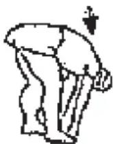
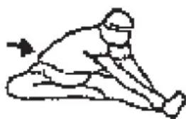
Bend forward as far forward as possible and let your legs almost stretched. Show it with your fingers in the direction of toe. 2 x 20sec.
natural_image
Simple line drawing of a person in a kneeling or stretching pose (no text or symbols)Sit down with one leg stretched out on the floor and bend forward and try to reach the foot with your hands. 2 x 20sec.
natural_image
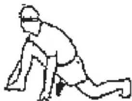
Simple line drawing of a person in a kneeling or stretching pose (no text or symbols)Kneel in a wide lunge forward and support yourself with your hands on the floor. Press the pelvis down. Change after 20 sec leg.
Parts list – List of spare parts
AX 7000 order No. 1908
Technical data: Issue: 01. 09. 2019
Ergometer of Class HA / EN 957-1/9 with high accuracy
• 24-stepped Motor – and Computer-controlled magnetic resistance
• Approx. 8 kg flywheel mass
• 10 stored training programs
• 4 heart rate programs
- 5 individual programs
• 1 manual program
• 1 speed independent program (30-350 Watt, resistance adjustable in 10 Watt steps)
• Hand pulse measurement at moveable grips
• Pedals 3- times adjustable
• Floor level compensation
- Transport rollers
• Power plug (Adapter)
- Back Light LCD Display, 6 window display shows simultaneously: Time, Speed, Distance, approx Calorie consumption, RPM, Watt and pulse frequency, Holder for smartphone / tablet
- Inputs of limits: Time, Distance, approx. Calories, Pulse frequency and Watt
• Announcement of limits
- Fitness- Test
• Body fat analysis (BMI)
- Load mx. 150 kg (Body weight)
Space requirement approx.: L 120 x W 60 x H 163 cm
Items weight: 40 kg
Exercise space approx: min. 3,5m²
Please contact us if any components are defective or missing, or if you need any spare parts or replacements in future.
Internet service- and spare parts data base: www.christopeit-service.de
This product is created only for private Home sports activity and not allowed to us in a commercial or professional area. Home Sport use class H/C

| Illu. No. | Designation Dimensions | mm | Quantity Attached to illustration No. | ET number |
| 1 Computer 1 30 36-1508203-BT | ||||
| 2 Fixed handle foam 2 3 36-1508-04-BT | ||||
| 3 Fixed handle 1 30 33-1908-03-SW | ||||
| 4 End cap 2 3 39-9847 | ||||
| 5L Hand grip left 1 25L 33-1508-11-SI | ||||
| 5R Hand grip right 1 25R 33-1508-12-SI | ||||
| 6 End cap 2 5 36-9825315-BT | ||||
| 7 Hand grip foam 2 5 36-1123-11-BT | ||||
| 8 Hand pulse sensor 2 5 36-1123-23-BT | ||||
| 9 Self-tapping screw M4x25 2 8 36-9111-38-BT | ||||
| 10 Hand pulse cable | 2 | 8+16 | 36-1123-12-BT | |
| 11 Screw head cover 2 12 36-1908-06-BT | ||||
| 12 Outer hexagon bolt M8x20 2 19 39-9823 | ||||
| 13 Adaptor 6V=DC/1000mA 1 39 36-9107-22-BT | ||||
| 14 Cable save 4 5+30 36-9134-22-BT | ||||
| 15 Screw M5x10 4 1 39-9903 | ||||
| 16 Pulse connection cable | 2 | 1+10 | 36-1123-24-BT | |
| 17 Nylon bushing 19x38 2 30 36-1508-09-BT | ||||
| 18 Grip cover 1 3 36-1908-07-BT | ||||
| 19 Hand grip axle | 1 | 25+30 | 33-9925462-SI | |
| 20 Washer 19//38 2 19 36-9925114-BT | ||||
| 21 Nylon bushing 18.5x38 4 25 36-9825328-BT | ||||
| 22 Washer 8//32 2 12 39-10166 | ||||
| 23 Allen bolt M10x78 2 25+44 39-10055-SW | ||||
| 24 Oval plug 30x60 2 44 36-1123-26-BT | ||||
| 25L Connection tube left | 1 | 5L+44L | 33-1508-08-SI | |
| 25R Connection tube right | 1 | 5R+44R | 33-1508-09-SI | |
| 26 Nylon nut M10 2 23 39-9981-VC | ||||
| 27 Washer 10//19 2 23 39-9989-CR | ||||
| 28 Steel tube 14x10x59.3 2 29 36-9925515-BT | ||||
| 29 Bushing 14x32 4 25 36-9925516-BT | ||||
| 30 | Handlebar post 1 40 33-1908-02-SW | |||
| 31 | Curved washer 8//19 12 33 36-9966-CR | |||
| 32 | Spring washer for M8 20 12, 33,48+59 39-9864-VC | |||
| 33 | Allen bolt M8x20 12 3,5+30 39-9886-CR | |||
| 34 | Connection cable | 1 1+35 | 36-1721-15-BT | |
| 35 | Motor cable | 1 34+63 | 36-1721-16-BT | |
| 36 | Cap nut | M8 | 4 59 39-9900-SW | |
| 37 | Washer | 8//16 4 59 39-9962 | ||
| 38 | Sensor cable | 1 35+40 | 36-1721-13-BT | |
| 39 | DC cable | 1 35+98 | 36-1721-07-BT | |
| 40 | Main frame | 1 30 33-1908-01-SW | ||
| 41 | Tension wire | 1 63+80 | 36-1721-10-BT | |
| 42 | Carriage bolt | M6x50 4 43+44 | 39-10450 | |
| 43L | Pedal left | 1 44R | 36-9825308-BT | |
| 43R | Pedal right | 1 44L | 36-9825309-BT | |
| 44L | Foot tube left | 1 | 25L+97 | |
| 44R | Foot tube right 1 25R+97 33-1908-07-SW | |||
| 45 | Washer | 6//14 4 42 39-9863 | ||
| 46 | Spring washer for M6 4 42 39-9865-SW | |||
| 47 | Hand grip nut | M6 | 4 42 36-9825318-BT | |
| 48 | Allen bolt M8x20 2 97 39-10095-SW | |||
| 49 | Washer | 8//24 2 48 39-9844-CR | ||
| 50 | C-clip | 40 | 2 44 36-1827-18-BT | |
| 51 | Bearing | 2203-2RS | 2 44 36-1827-30-BT | |
| 52 | Steel tube | 17.5x22x12 | 2 97 36-1908-16-BT | |
| 53 | Plastic cover | 2 44 36-1908-11-BT | ||
| 54 | Screw | M5x8 | 2 53 39-9903 | |
| 55L | Front stabilizer cap left | 1 56 36-1908-08-BT | ||
| 55R | Front stabilizer cap right | 1 56 36-1908-09-BT | ||
| 56 | Front stabilizer | 1 40 33-1908-04-SW | ||
| 57 | Rear stabilizer cap | 2 58 36-1908-10-BT | ||
| 58 | Rear stabilizer | 1 40 33-1908-05-SW | ||
| 59 | Carriage bolt | M8x45 4 40,56+58 | 39-9953 | |
| 60 | Drill screw | M5x20 10 38,55,57+63 | 39-9903-SW | |
| 61 | Axis protection piece | 2 62 36-1123-28-BT | ||
| 62 | Axle nut | M10x1.25 | 2 64 39-9820-SW | |
| 63 | Serve motor | 1 35+41 | 36-1721-09-BT | |
| 64 | Flywheel | 1 40 33-0908-07-SI | ||
| 65 | Eye bolt | M6x40 | 2 64 39-10000 | |
| 66 | U-piece | 2 65 36-9713-55-BT | ||
| 67 | C-clip | C8 | 1 71 36-9514-26-BT | |
| 68 | Washer | 10//15 1 71 36-1508-12-BT | ||
| 69 | Wave washer | 10x15x0.5 | 1 71 36-1508-11-BT | |
| 70 | Idler wheel | 1 71 36-9214-28-BT | ||
| 71 | Axle idler wheel | 1 40+70 | 36-1908-13-BT | |
| 72 | Nylon nut | M10 | 1 71 39-9981-VC | |
| 73 | Nut | M6 | 4 65+74 | 39-9861-VZ |
| 74 | Double-thread screw | 1 40+80 | 36-1611-22-BT | |
| 75 | Silicone washer | 8//16 1 74 39-9917-CR | ||
| 76 | Nylon nut | M6 | 5 74 39-9816-VC | |
| 77 | Spring | 1 80 36-9806217-BT | ||
| 78 | Allen bolt M6x15 6 81+91 39-9911 | |||
| 79 | Washer | 6//14 3 78 39-9863 | ||
| 80 | Magnet bracket | 1 81 33-1611-14-SI | ||
| 81 | Axle magnet bracket | 1 80 36-9225-11-BT | ||
| 82 Spring washer for M6 6 78+92 39-9865-SW | ||||
| 83 Magnet 1 89 36-9825506-BT | ||||
| 84 C-clip C20 1 91 36-9925520-BT | ||||
| 85 Washer 20.5x25x2 1 91 36-9925523-BT | ||||
| 86 Bearing 6004-2RS 2 40 36-9217-32-BT | ||||
| 87 Washer 20.5x25x1 1 91 36-9925523-BT | ||||
| 88 Wave washer 20x25x0.5 1 91 36-9925532-BT | ||||
| 89 Belt wheel | 1 91 36-1908-14-BT | |||
| 90 Belt | 520J6 | 1 64+89 36-9126-59-BT | ||
| 91 Pedal axle | 1 89+93 33-1908-10-SI | |||
| 92 Axle nut | 2 91+93 39-9820-SW | |||
| 93 Crossing welding | 2 91 33-1908-08-SI | |||
| 94 Crank plug | 2 95 36-1908-15-BT | |||
| 95 Circle cover | 2 97 36-1908-04-BT | |||
| 96 Screw | M8x20 | 6 93+97 39-9886-CR | ||
| 97 Crank | 2 93 33-1908-09-SI | |||
| 98L Chain cover left | 1 | 40+98R | 36-1908-01-BT | |
| 98R Chain cover right | 1 | 40+98L | 36-1908-02-BT | |
| 99 Connection shaft | 1 98 36-1508-10-BT | |||
| 100 Rubber plug | 1 | 101 | 36-1908-12-BT | |
| 101 Plastic cover | 1 30 36-1908-05-BT | |||
| 102 Screw | M5x15 | 7 | 18,93+95 | 39-10190 |
| 103 Drill screw | M5x15 | 7 98 39-9851 | ||
| 104 Self-tapping screw | M4.5x25 | 7 | 98 | 39-9825338-BT |
| 105 Multi wrench | 2 | 36-9107-28-BT | ||
| 106 Allen wrench | 6 | 1 | 36-9107-27-BT | |
| 107 Assembly and exercise instructions | 1 | 36-1908-17-BT | ||
Etape n° 2 :
natural_image
Three sequential illustrations of a woman performing an exercise on an easotop bike (no text or symbols)Monter, utiliser & descendre
Transport de la machine:
DUREE (Time) / WATT:
Programm 3 Fatburn Programm 4 Ramp Programm 5 Mountain
Programm 6 Interval Programm 7 Cardio Programm 8 Endurance
Programm 9 Slope Programm 10 Rally
User Setting Program 11 (U1)
User Setting Program 12 (U2)

User Setting Program 13 (U3)
User Setting Program 14 (U4)
User Setting Program 15 (U5)

Programm 16 Watt Control Program
Programm 17 HRC (55%)
Programm 18 HRC (75%)
Programm 19 HRC (95%)

Programm 20 HRC
PROGRAMME 1 : Manuel
line
| Maximum pulse rate (200-100) | 70% des Maximalpulses | 85% des Maximalpulses | 90% des Maximalpulses | Maximum pulse rate (200-100) | |---|---|---|---|---| | 20 | 140 | 135 | 140 | 200 | | 25 | 136 | 133 | 136 | 195 | | 30 | 133 | 129 | 133 | 190 | | 35 | 129 | 126 | 129 | 185 | | 40 | 126 | 122 | 126 | 180 | | 45 | 122 | 119 | 122 | 175 | | 50 | 119 | 116 | 119 | 170 | | 55 | 116 | 113 | 116 | 165 | | 60 | 112 | 110 | 112 | 160 | | 65 | 109 | 107 | 109 | 155 | | 70 | 106 | 104 | 106 | 150 | The chart displays a descending trend in pulse rate as the maximum pulse rate increases from 20 to 70. The legend defines four lines: 'Maximalpuls (220-After)' at the top, '90% des Maximalpulses' at the middle, '85% des Maximalpulses' at the lower middle, and '70% des Maximalpulses' at the bottom right. The data points are labeled with precise numerical values on each line. The chart is saved as a PNG file named 'chart_footnote.png'.natural_image
Simple line drawing of a person in a kneeling pose with an arrow indicating motion (no text or symbols)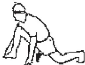
natural_image
Line drawing of a person in a kneeling or stretching pose (no text or symbols)
natural_image
Three-step diagram showing a woman performing an exercise on an easotop bike, with no text or symbols present.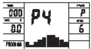
Programm 6 Interval Programm 7 Cardio Programm 8 Endurance
Programm 9 Slope
Programm 10 Rally
User Setting Program 11 (U1)
User Setting Program 12 (U2)

User Setting Program 13 (U3)
User Setting Program 14 (U4)
User Setting Program 15 (U5)

Programm 16 Watt Control Program Programm 17 HRC (55%)

Programm 18 HRC (75%)

Programm 19 HRC (95%)
Programm 20 HRC
Programma manual: handmatig
Programma's 1-10: fitness
3. Planning van de training
line
| Maximum pulse rate (200-After) | 90% des Maximalpulses | 85% des Maximalpulses | 70% des Maximalpulses | |---|---|---|---| | 20 | 195 | 190 | 180 | | 25 | 175 | 190 | 165 | | 30 | 171 | 185 | 161 | | 35 | 166 | 180 | 157 | | 40 | 162 | 175 | 153 | | 45 | 157 | 170 | 148 | | 50 | 153 | 165 | 144 | | 55 | 148 | 160 | 140 | | 60 | 144 | 155 | 136 | | 65 | 139 | 150 | 131 | | 70 | 135 | 145 | 127 | The chart displays a single line representing the maximum pulse rate at each threshold. The x-axis ranges from 20 to 70, and the y-axis ranges from 100 to 220. The legend defines four distinct lines: 'Maximalpuls (220-After)' (black), '90% des Maximalpulses' (black), '85% des Maximalpulses' (black), and '70% des Maximalpulses' (black). The chart is annotated with the number above each data point, indicating the percentage of maximum pulse rate at that threshold. The values are explicitly labeled on the chart.natural_image
Simple line drawing of a person in a kneeling pose, no text or symbols present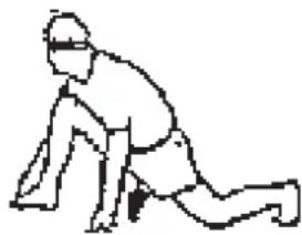
natural_image
Simple line drawing of a person in a kneeling or stretching pose (no text or symbols)War 2:


natural_image
Three-step line drawing of a woman performing exercise on an outdoor bike (no text or symbols)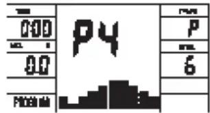
Programm 6 Interval Programm 7 Cardio Programm 8 Endurance
Programm 9 Slope
Programm 10 Rally
User Setting Program 11 (U1)
User Setting Program 12 (U2)

User Setting Program 13 (U3)

User Setting Program 14 (U4)
User Setting Program 15 (U5)

Programm 16 Watt Control Program Programm 17 HRC (55%)
Programm 18 HRC (75%)

Programm 19 HRC (95%)

Programm 20 HRC
natural_image
Simple line drawing of a person in a kneeling pose (no text or symbols)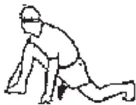
natural_image
Simple line drawing of a person in a kneeling position (no text or symbols)Русский
© by Top-Sports Gilles GmbH
D-42551 Velbert (Germany)
Service:
Top-Sports
Gilles
GmbH
Tel.: +49 (0)2051/6067-0
Friedrichstrasse 55
info@christopeit-sport.com
Fax: +49 (0)2051/6067-44
D - 42551 Velbert
http://www.christopeit-sport.com