CX 6 - Elliptical bike Christopeit - Free user manual and instructions
Find the device manual for free CX 6 Christopeit in PDF.

User questions about CX 6 Christopeit
0 question about this device. Answer the ones you know or ask your own.
Ask a new question about this device
Download the instructions for your Elliptical bike in PDF format for free! Find your manual CX 6 - Christopeit and take your electronic device back in hand. On this page are published all the documents necessary for the use of your device. CX 6 by Christopeit.
USER MANUAL CX 6 Christopeit
natural_image
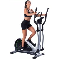
Woman exercising on an outdoor fitness bike with a circular exercise machine (no visible text or symbols)D
Assembly and exercise instructions for Order No.
F
text_image
Technical diagram of a stationary exercise machine with numbered components and labeled parts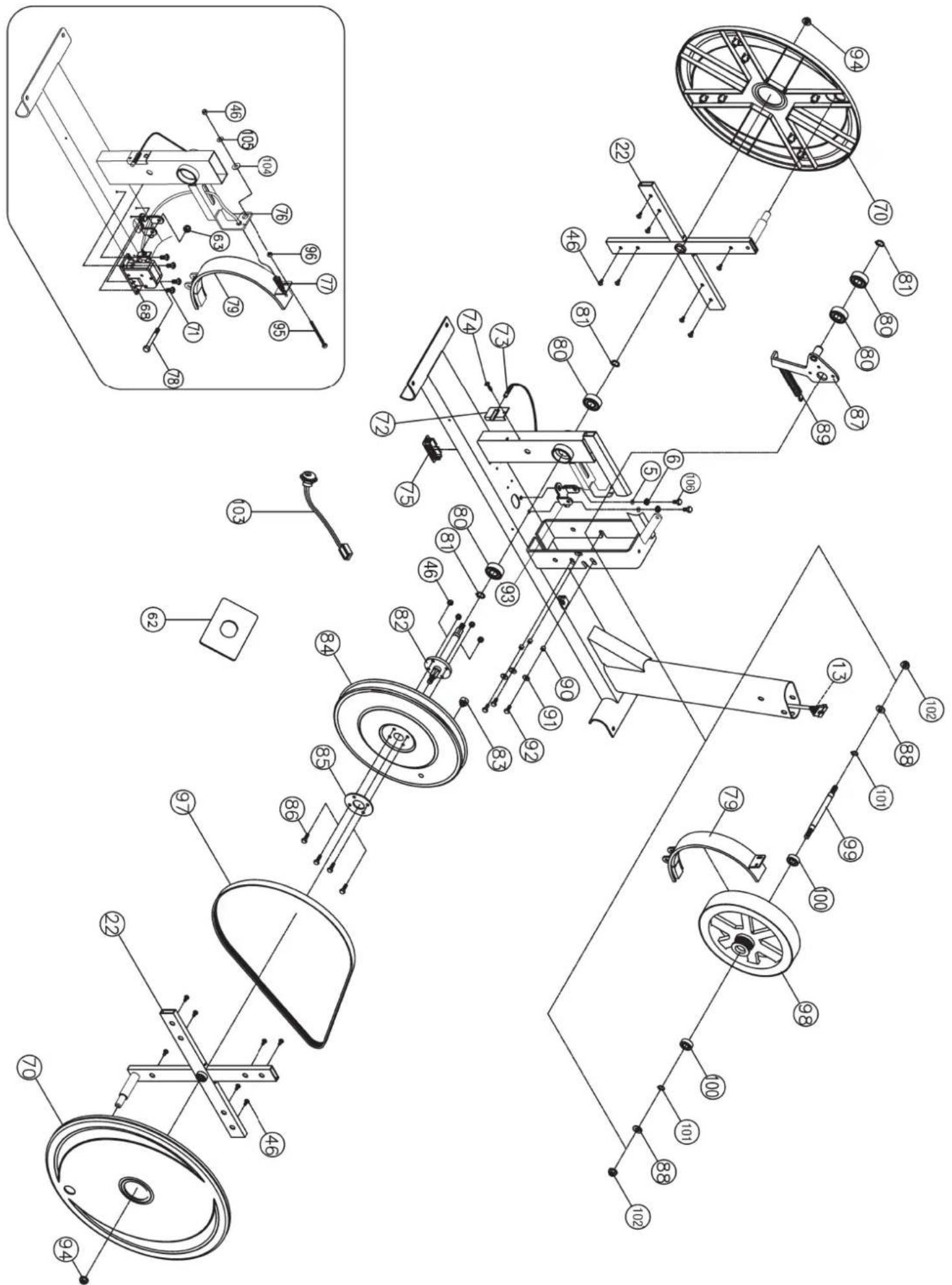
text_image
Technical schematic diagram of a mechanical device with numbered components and exploded viewstext_image
Technical diagram of a mechanical assembly with numbered components for identificationSchritt 2:
text_image
Technical diagram showing numbered components of a mechanical or electrical assembly with directional arrows and dotted lines indicating connections.Schritt 3:
text_image
Technical diagram of a mechanical assembly with numbered components and labeled parts A and Btext_image
Technical diagram of a mechanical device with numbered components for identificationtext_image
Technical diagram of a stationary exercise machine with numbered components and motion arrows indicating movement paths.text_image
Technical diagram of a stationary exercise machine with numbered components for identification.text_image
Technical diagram of a solar panel assembly with numbered components and a reference label Rtext_image
Technical diagram of an exercise bike with labeled components and a close-up view of the device's body parts.55% H.R.C., 65% H.R.C., 75% H.R.C., 85% H.R.C., Ziel H.R.C.
natural_image
Grid of black and white squares with no text or symbolsBENUTZER - PRoGRAMME
PROGRAMM 14
HERZFREQUENZ-
PRoGRAMMPRoFILE
PROGRAMM 18

text_image
55% H.R.C. "E"-Taste drückenPROGRAMM 19
text_image
65% H.R.C. E"-Taste drückenPROGRAMM 20

text_image
75% H.R.C. E"-Taste drückenPROGRAMM 21
text_image
85% H.R.C. E"-Taste drückenZIEL HERZFREQUENZ-
PRoGRAMME
PROGRAMM 22

text_image
ZIEL H.R.C.PROGRAMM 23
flowchart
graph TD
    A["WATT KONTROLLE"] --> B["KÖRPERFETT - TESTPROGRAMM: PROGRAMM 24"]
    C["BODY FAT (STOP MODUS)"] --> D["BODY FAT (START MODUS)"]
- Summary of Parts Page 3 - 4
- Important Recommendations and Safety Information Page 18
- Parts List (List of spare parts) Page 19 - 21
- Assembly Instructions With Exploded Diagrams Page 22 - 25
- Computer instructions Page 26 - 30
- Training Instructions Page 31
Dear customer,
We congratulate you on your purchase of this home training sports unit and hope that we will have a great deal of pleasure with it. Please take heed of the enclosed notes and instructions and follow them closely concerning assembly and use.
Please do not hesitate to contact us at any time if you should have any questions.
Important Recommendations and Safety Instructions
Our products are all TÜV-GS tested and therefore represent the highest current safety standards. However, this fact does not make it unnecessary to observe the following principles strictly.
-
Assembly the machine exactly as described in the installation instructions and use only the enclosed, specific parts of the machine contained in the parts list. Before assembling, verify the completeness of the delivery against the delivery notice and the completeness of the carton against the parts list in the installation and operating instructions.
-
Check the firm seating off all screws, nuts and other connections before using the machine for the first time and at regular intervals to ensure that the trainer is in a safe condition.
-
Set up the machine in a dry, level place and protect it from moisture and water. Uneven parts of the floor must be compensated by suitable measures and by the provided adjustable parts of the machine if such are installed. Ensure that no contact occurs with moisture or water.
-
Place a suitable base (e.g. rubber mat, wooden board etc.) beneath the machine if the area of the machine must be specially protected against indentations, dirt etc.
-
Before beginning training, remove all objects within a radius of 2 metres from the machine.
-
Do not use aggressive cleaning agents to clean the machine and employ only the supplied tools or suitable tools of your own to assemble the machine and for any necessary repairs. Remove drops of sweat from the machine immediately after finishing training.
-
WARNING! Your health can be impaired by incorrect or excessive training. Consult a doctor before beginning a planned training programme. He can define the maximum exertion (pulse, Watts, duration of training etc.) to which you may expose yourself and can give you precise information on the correct posture during training, the targets of your training and your diet. Never train after eating large meals.
-
Only train on the machine when it is in correct working order. Use original spare parts only for any necessary repairs. WARNING: Replace the worm parts immediately and keep this equipment out of use until repaired.
-
When setting the adjustable parts, observe the correct position and the marked, maximum setting positions and ensure that the newly adjusted position is correctly secured.
-
Unless otherwise described in the instructions, the machine must only be used for training by one person at a time. The exercise time should not overtake 90 min./daily.
-
Wear training clothes and shoes which are suitable for fitness training with the machine. Your clothes must be such that they cannot catch during training due to their shape (e.g. length). Your training shoes should be appropriate for the trainer, must support your feet firmly and must have non-slip soles.
- WARNING! If you notice a feeling of dizziness, sickness, chest pain or other abnormal symptoms, stop training and consult a doctor.
- Never forget that sports machines are not toys. They must therefore only be used according to their purpose and by suitably informed and instructed persons.
- People such as children, invalids and handicapped persons should only use the machine in the presence of another person who can give aid and advice. Take suitable measures to ensure that children never use the machine without supervision.
- Ensure that the person conducting training and other people never move or hold any parts of their body into the vicinity of moving parts.
- At the end of its life span this product is not allowed to dispose over the normal household waste, but it must be given to an assembly point for the recycling of electric and electronic components. You may find the symbol on the product, on the instructions or on the packing.
The materials are reusable in accordance with their marking. With the re-use, the material utilization or the protection of our environment. Please ask the local administration for the responsible disposal place. - For speed dependent operation mode, the braking resistance level can be adjustable manually and the variations of power will depend on the pedaling speed. For speed independent operation mode, the user can set the wanted power consumption level in Watt, constant power level will be kept by various braking resistance levels, that will be determined automatically by system. That is independent on the pedaling speed.
- The unit has a resistance device with 16 levels. This makes it possible to increase or reduce the braking resistance and thus the amount of effort required in the training. Pressing the button „-“ reduces the braking resistance and thus the amount of effort required in the training. Pressing the button „+“ increases the braking resistance and thus the amount of effort required in the training.
- This machine has been tested and certified in compliance with EN 957-1 and -9 "H,A". The maximum permissible load (=body weight) is specified as 150 kg. The classification of HA means this exercise bike is designed foe home use only and with good accuracy class, the variations of power consuming are within ±5W up to 50W and ±10% over 50W. This item's computer corresponds to the basic demands of the EMV Directive of 2004/108/EC.
Parts list – List of spare parts CX 6 order No. 9126(A), 9126, 9127
Technical data: Issue: 01.09.2011
Ergometer of Class HA / EN 957-1/9 with high accuracy
• Motor- and Computer-controlled magnetic resistance
• Approx 12 kg flywheel
• 11 stored training programs
- 5 stored heart frequency training programs
- 5 individual programs, 16 manually adjustable load steps
• 1 Body fat program
- 1 speed independent program (40 – 400 Watt, resistance adjustable in 10 Watt steps)
• Hand pulse measurement
• Teflon coated plastic bearing with good emergency run quality
• Floor level compensation
• Transport rollers at front foot
• Power plug
- Blue / Green Back Light LCD Display with, speed, distance, time, approx calorie consumption, pedal revolutions per minute, pulse frequency and Watt
• Input of limits for time, speed and approx calories
• Announcement of higher limits
- Fitness - Test
- Load max. 150 kg (Body weight)
Please check after opening the packing that all the parts shown in the following parts lists are there. Once you are sure that this is the case, you can start assembly.
Please contact us if any components are defective or missing, or if you need any spare parts or replacements in future:
Installation instructions
Before beginning with installation, be sure to observe our recommendations and safety instructions.
Some parts are preassembled.
Step 1:
Installation of front foot (2) and rear foot (8) on the main frame (1).
- Place the bolts (4) and each two washers (5), spring washers (6) and nuts (7) ready for use beside the front and rear part of the main frame (1).
- Place the front foot (2) and rear foot (8) into the bracket of the main frame (1) and align so that the hole patterns of the bracket and the foots are in conformance.
(Note: The front foot caps with transport roller units (3) installed in the front foot bar (2) must point forwards (as viewed when training, standing on the machine). - Push one screw (4) each through the bores.
- Install one washer (5) and one spring washer (6) each on the ends of the screws (4) and fasten with one nut (7) each. (You can use adjustable screw (67) to level the bike.)

text_image
Technical diagram of mechanical assembly with numbered components for identificationStep 2:
Connecting the computer cables (13+14) and installation of handlebar post (15).
- Place the lower end of the handlebar post (15) against the main frame (1). Connect the two ends of the computer cable (13) and (14) projecting from (1) and (15).
- When the electrical cable connections have been made, push the handlebar post (15) into the main frame (1). (Note. When pushing the tubes together, ensure that the electrical cable connection is not trapped. The short tube welded crosswise to the upper end of the tubular support (15) must point forwards (as viewed when training standing on the machine).
- Push one spring washer (6) and one washer (5) on each of the bolts (12). Push the bolts (12) through the bores in the main frame (1), screw into the threaded holes of the handlebar post (15) and tighten firmly.

text_image
Technical diagram showing numbered components of a mechanical or electrical assembly with directional arrows and dotted lines indicating connections.Step 3:
Installation of the right (20) and left handgrip (18) on the handlebar post (15) with the axle support (17).
- Push the axle support (17) centrally into the tube welded crosswise to the handlebar post (15).
- Push on the handgrip (20) from the right hand side and the handgrip (18) from the left hand side.
(Note. After installation, the handgrips must be aligned in such a manner that the upper ends are inclined outwards (from handlebar post (15)). - Push one spring washer (6) and one washer (16) onto each screw (12), screw the screws (12) into the threaded holes at both ends of the axle support (17) and tighten firmly.
(Note. The handgrips are heavier at the top than at the bottom. Twist the handgrips downwards until further installation is conducted.) - If the arms appear to move too much sideways, please carry out the Following procedure; Remove the assembly bolt from either end of the Metal shaft, place one or more of the 0.15mm spacers (A) provided on to The shaft, as shown in the picture and then re-fit the assembly bolt.

text_image
Technical diagram of a mechanical assembly with numbered components and labeled parts A and BStep 4: Installation of the small handle bar (43) with small handlebar bracket (44) on handlebar post (15).
- Place the small handlebar bracket (44) on the small handle bar (43) in such a manner that the bores in the bracket and those at the end of the handlebar are aligned.
- Place the whole assembly against the upper end of the handlebar post (15) through the thread bolts and tighten it with washer (45) spring washer (32) and self lock nut (46) firmly.
(Note: The handle bar must be aligned so that it is inclined away from the handlebar post (15).) - Put into the each end of small handlebar (43) one end cap (47).

text_image
Technical diagram of a mechanical device with numbered components for identificationStep 5: Installation of the right and left pedal tube (21+24) with swivel tube (26) on the left and right handle bar (18+20) and cross frames (22+104).
- Push the end of the right pedal tube (24) onto the cross frame (22) and tighten it with screw (23), washer (16) and spring washer (6) at the cross frame (22) firmly.
- Push the swivel tube (26) into the right handle bar (20) and tighten it with screws (12), spring washer (6) and washer (27) firmly.
- Install the left pedal tube (21) with all additionally required parts on the left hand side of the machine as described in 1. + 2.

text_image
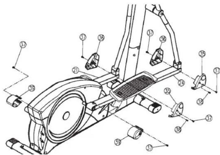
Technical diagram of a stationary exercise machine with numbered components and motion arrows indicating movement paths.Step 6: Installation of the front and rear pedal cover (35, 36+39) on the pedal tubes (21+24).
- Push the rear pedal tube cover (39) onto the connection point of cross frame (22+104) and pedal tube (21+24) and fasten it with screw (37).
- Put each one of left and right pedal front cover (35+36) onto one connection point of swivel tube (26) and pedal tubes (21+24) together and fasten them with screws (37+38).
text_image
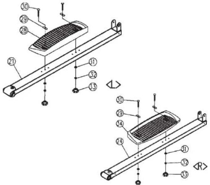
Technical diagram of a stationary exercise machine with numbered components for identification.Step 7: Installation of the right (34) and left (28) footrest on the pedal tubes (21+24).
- Push the footrest (34) onto the pedal tube (24) so that the bores in (34) are aligned with one of the possible installation positions in (24). (Note. The high lip on the long side of the footrest must point inwards (towards the main frame (1).)
- Put one washer (29) on each carriage bolt (30) and push through the bores from the top and fasten from the bottom with the washers (31), the spring washers (32) and the knob down (33).
(Note. The position adjusted in this way should always be equal at both sides. The positions can be changed as desired at all times by removing the carriage bolts (30) and sliding the footrests on the footrest brackets.)
- Install the left footrest (28) with all additionally required parts on the left hand side of the machine as described in 1. +2.
text_image
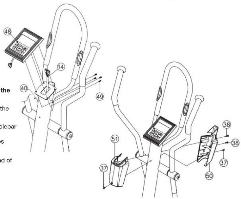
Technical diagram of a solar panel assembly with numbered components and a reference label RStep 8: Installation of the computer (48) and handle bar cover (50+51) on the handlebar post (15).
- Put the ends of the computer cable (14) and pulse cable (40) into the socket at the backside of the computer (48).
- Push the computer (48) onto the plate at the upper end of the handlebar post (15).
(Note: When pushing on the computer, thread the cables in the bores of the handlebar post (15) so that the cables cannot be trapped. - Put the front and back handlebar cover (50+51) onto the upper end of handlebar post (15) together and fix them with screws (37+38).
text_image
Technical diagram of a stationary exercise machine with numbered components and Chinese explanatory text labelsStep 9: Attach the power
- Please insert the plug of adaptor (52) to the jack (103) of chain guard.
- Please insert the adaptor (52) to the jack of wall power (230V/50Hz).

text_image
Technical diagram of an exercise bike with labeled components and a close-up view of the device's internal structure.Step 10: Checks
- Check the orderly installation and function of all bolted and plug connections. Installation is then complete.
- When everything is in order, familiarise yourself with the machine at a light resistance setting and make the individual adjustments of the footrests (28) and (34).
Note: Please keep the tool set, the puller and the instructions carefully because these may be required later for repairs or spare parts orders. If you ever remove the covers (10) and (11), observe that these are attached not only outwardly with the screws (64+65), but also inwardly at the rear end of the cover with the screws (65).
Mount, Use & Dismount
Transportation of Equipment:
There are two rollers equipped on the front foot. For moving, you can lift up the rear foot and drive it to where you would like to locate or store it.
Mount, Use & Dismount
Mount:
a. Stand beside the item, put the nearest footrest into deepest position and hold the fixed handlebar tightly.
b. Put your foot onto the footrest, try to put whole body weight on your foot and simultaneously cross over with your another foot on the other side footrest and place there on the footrest too.
c. Now you are in the position to start your training.
Use:
a. Keep your hands in desired position on the fixed handlebar.
b. Pedal your exercise item by step your feet on footrests and balance the body weight to left and right side of footrest
c. If you like to exercise the upper body too, you can place the hands from fixed handle bar to the left and right handle grips.
d. Then you can increase the pedaling speed gradually and adjust braking resistance levels to increase the exercise intension.
e. Keep always your hands on fixed handle bar or hand grips left and right.
Dismount:
a. Slow down the pedaling speed until it comes to rest.
b. Keep the hands grabbing the fixed handlebar tightly, put one foot cross over the equipment and land on the floor, then land the other one.
This training equipment is a stationary exercise machine used to simulate a combination of biking, stepping and walking without causing excessive pressure to the joints, hence decreasing the risk of impact injuries.
Exercise this item offers a non-impact cardiovascular workout that can vary from light to high intensity based on the resistance preference set by the user. It will strengthen your muscles of upper and lower body and increase cardio capacity and maintain fitness of your body also.
| Test Title: RPM and Wattage from Level 1 to Level 16 | 9126, 9127 | CX 6 | Year: 2009 | |||||||||||||||
| WATTAGE RPM\Load | 1 | 2 | 3 | 4 | 5 | 6 | 7 | 8 | 9 | 10 | 11 | 12 | 13 | 14 | 15 | 16 | ||
| 40 RPM | Console Ave. Value | 25 | 34 | 42 | 51 | 60 | 69 | 79 | 88 | 97 | 106 | 115 | 123 | 133 | 142 | 151 | 160 | |
| 50 RPM | Console Ave. Value | 38 | 51 | 64 | 77 | 91 | 105 | 119 | 133 | 146 | 160 | 174 | 186 | 200 | 215 | 228 | 242 | |
| 60 RPM | Console Ave. Value | 50 | 69 | 88 | 107 | 126 | 145 | 164 | 183 | 202 | 221 | 240 | 259 | 278 | 297 | 316 | 335 | |
| 70 RPM | Console Ave. Value | 69 | 91 | 114 | 140 | 163 | 188 | 214 | 237 | 263 | 289 | 312 | 338 | 361 | 387 | 409 | 436 | |
Remarks:
- The power consumptions (Watt) are calibrated by measuring the driving speed (min-1) of axle and the braking torque (Nm).
- Your equipment was calibrated to fulfill the requirements of its accuracy classification before shipment, If you have doubts about the accuracy, please contact with your local retailer or send it to accredited test laboratory to ensure or calibrate it.
Computer instruction for CX 6
text_image
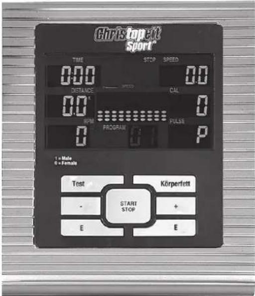
Christopelt Sport TIME STOP SPEED 0.0 0.0 DISTANCE CAL 0.0 0 RPM PROGRAM PULSE 0 P 1 = Male 0 = Female Test Körperfett - START STOP + E EThe things you should know before exercise
A. Input Power
Plug in the adaptor to the equipment then the computer will produce a beep sound and turn on the computer at the Manual mode.
B. Program select and setting value
- Use the UP or DOWN keys to select program mode and then press ENTER to confirm your exercise mode.
- At the Manual mode, the computer will use the UP or DOWN keys to set up your exercise TIME, DISTANCE, CALORIES.
- Press the START/STOP key to start exercise.
- When you reach the target, the computer will produce beep sounds and then stop.
- If you set up more than one target and you would like to reach next target, press START/STOP key to keep on exercise.
C. Clock Mode:
- After plug-in AC adaptor then the LCD will display at the Clock mode for user to input the current hour by 24 hours and minute by 60 minutes. After setting up the clock then the monitor will display the hour-minute and second bar on the screen. Two seconds display one bar. Also display the current temperature on the screen. Press any key to quit the CLOCK mode except the ENTER key.
- The computer will enter the clock mode when there is no signal input or no keys be pressed after 4 minutes. You can press ENTER key to switch the clock and temperature at the clock mode or press other keys to quit the clock mode except the ENTER key.
- By holding the ENTER and UP keys together for over two seconds, you can switch to the CLOCK mode during the STOP mode.
- You can set up the CLOCK by holding ENTER key for over 2 seconds when switch to CLOCK mode from STOP mode then you can set up TIME by UP or DOWN keys.
Functions and Features:
- START/STOP key: Allows you to start the computer without selecting a program. TIME automatically begins to count up from zero. Use the UP and DOWN keys to adjust the resistance.
- TIME: Shows your elapsed workout time in minutes and seconds. Your computer will automatically count up from 0:00 to 99:59 in one second intervals. You can also program your computer to count down from a set value by using the UP and DOWN keys. If you continue exercising once the
time has reached 0:00, the computer will begin beeping, and reset itself to the original time set, letting you know your workout is done.
-
DISTANCE: Displays the accumulative distance traveled during each workout up to a maximum of 99.9KM/MILE.
-
RPM: Your pedal cadence.
-
WATT: The amount of mechanical power the computer is receiving from your exercise.
-
SPEED: Displays your workout speed value in KM/MILE per hour.
-
CALORIES: Your computer will estimate the cumulative calories burned at any given time during your workout.
-
PULSE: Your computer displays your pulse rate in beats per minute during your workout.
-
AGE: Your computer is age-programmable from 10 to 99 years. If you do not set an age, this function will always default to age 35.
-
TARGET HEART RATE (TARGET PULSE): The heart rate you should maintain is called your Target Hear Rate in beats per minute.
-
PULSE RECOVERY: During the START stage, leave the hands holding on grips or leave the chest transmitter attached and then press "PULSE RECOVERY" key, all function displays will stop except "TIME". Time starts counting from 00:60 - 00:59 -- to 00:00. As soon as 00:00 is reached, the computer will show your heart rate recovery status with the grade F1.0 to F6.0.
1.0 means OUTSTANDING
1.0 < F < 2.0 means EXCELLENT
2.0 ≤ F ≤ 2.9 means GOOD
3.0 ≤ F ≤ 3.9 means FAIR
4.0 ≤ F ≤ 5.9 means BELOW AVERAGE
6.0 means POOR
Note: If no pulse signal input then the computer will show "P" on the PULSE window. If the computer shows "ERR" on the message window, please re-press the PULSE RECOVERY key and please make sure your hands are keeping well on the grips or the chest transmitter is attached well.
Key function:
There are 6 button keys and the function description as follows:
1. START/STOP key:
a. Quick Start key function: Allows you to start the computer without selecting a program. Manual workout only. Time automatically begins to count up from zero
b. During the exercise mode, press the key to STOP exercise.
c. During the stop mode, press the key to START exercise.
2. UP key:
a. Press the key to increase the resistance during exercise mode.
b. During the setting mode, press the key to increase the value of Time, Distance, Calories, Age and select Gender and Program.
3. DOWN key:
a. Press the key to decrease the resistance during exercise mode.
b. During the setting mode, press the key to decrease the value of Time, Distance, Calories, Age and select Gender and Program.
4. ENTER/RESET key:
a. During the setting mode, press the key to accept the current data entry.
b. At the stop mode, by holding this key for over two seconds the user can reset all values to zero or default value.
c. During setting the Clock, press this key can accept the setting hour and setting minute.
-
BODY FAT / MEASURE key: Press the key to input your HEIGHT, WEKGHT, GENDER and AGE then to measure your body fat ratio,
-
PULSE RECOVERY key: Press the key to activate heart rate recovery function.
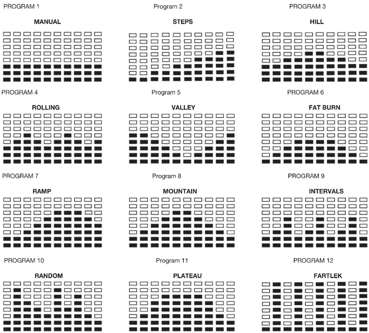
Program Introduction & Operation:
Manual Program: Manual
P1 is a manual program. User can start exercise by pressing START/STOP key. The default resistance level is 5. Users may exercise in any desirous of resistance level (Adjusting by UP/DOWN keys during the workout) with a period of time or a number of calories or a certain distance.
Operations:
- Use UP/DOWN keys to select the MANUAL (P1) program.
- Press the ENTER key to enter MANUAL program.
- The TIME will flash and you can press UP or DOWN keys to setting your exercise TIME. Press ENTER key to confirm your desired TIME.
- The DISTANCE will flash and you can press UP or DOWN keys to setting your target DISTANCE. Press ENTER key to confirm your desired DISTANCE.
- The CALORIES will flash and you can press UP or DOWN keys to setting your exercise CALORIES. Press ENTER key to confirm your desired CALORIES.
- Press the START/STOP key to begin exercise.
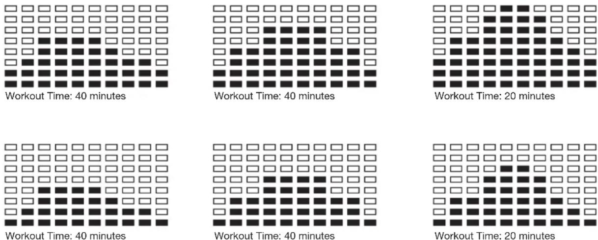
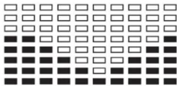
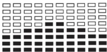
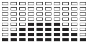
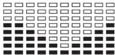
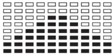
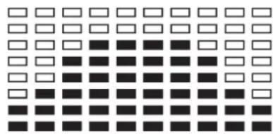
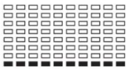
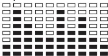
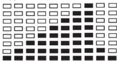
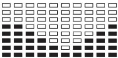
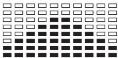
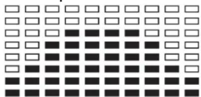
Preset Program: Steps, Hill, Rolling, Valley, Fat Burn, Ramp, Mountain, Intervals, Random, Plateau, Fartlek, Precipice Program
PROGRAM 2 to PROGRAM 13 is the preset programs. Users can exercise with different level of loading in different intervals as the profiles show. Users may exercise in any desirous of resistance level (Adjusting by UP/DOWN keys during the workout) with a period of time or a number of calories or a certain distance.
Operations:
-
Use UP/DOWN keys to select one of the above programs from P2 to P13.
-
Press the ENTER key to enter your workout program.
- The TIME will flash and you can press UP or DOWN keys to setting your exercise TIME. Press ENTER key to confirm your desired TIME.
- The DISTANCE will flash and you can press UP or DOWN keys to setting your target DISTANCE. Press ENTER key to confirm your desired DISTANCE.
5 The CALORIES will flash and you can press UP or DOWN keys to setting your exercise CALORIES. Press ENTER key to confirm your desired CALORIES. - Press the START/STOP key to begin exercise.
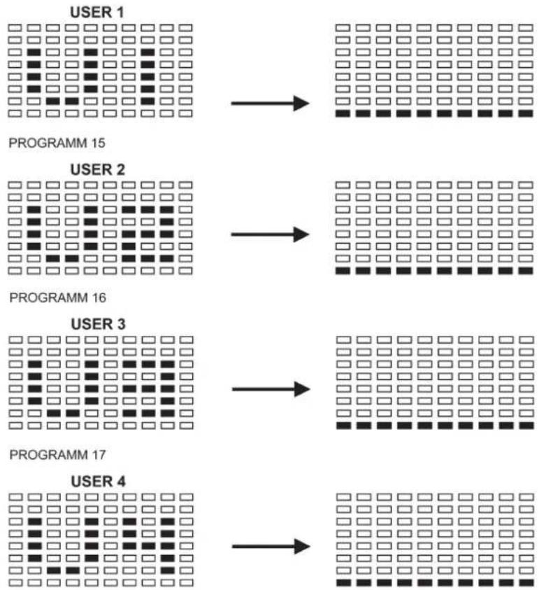
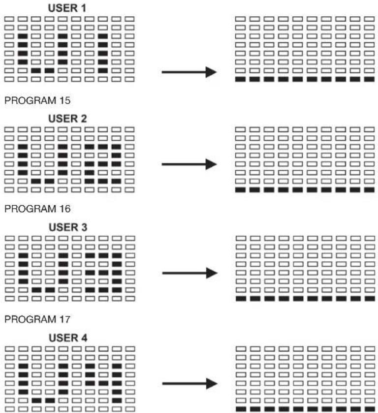
User Setting Program:
User 1, User 2, User 3 and User 4
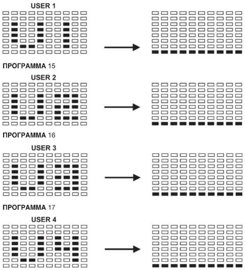
Program 14 to 17 is the user setting program. Users are free to create the values in the order of TIME, DISTANCE, CALORIES and the resistance level in 10 columns. The values and profiles will be stored in the memory after setup. Users may also change the ongoing loading in each column by UP/DOWN keys, and they will not change the resistance level stored in the memory.
Operations:
- Use UP/DOWN keys to select the USER program from P14 to P17.
- Press the ENTER key to enter your workout program.
- The column 1 will flash, and then use the UP/DOWN keys to create your personal exercise profile. Press ENTER to confirm your first column of exercise profile. The default level is load 1.
- The column 2 will flash, and then use the UP/DOWN keys to create your personal exercise profile. Press ENTER to confirm your second column of exercise profile.
- Follow the above description 5 and 6 to finish your personal exercise profiles. Press ENTER to confirm your desired exercise profile.
- The TIME will flash and you can press UP or DOWN keys to setting your exercise TIME. Press ENTER key to confirm your desired TIME.
- The DISTANCE will flash and you can press UP or DOWN keys to setting your target DISTANCE. Press ENTER key to confirm your desired DISTANCE.
- The CALORIES will flash and you can press UP or DOWN keys to setting your exercise CALORIES. Press ENTER key to confirm your desired CALORIES.
- Press the START/STOP key to begin exercise.
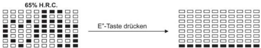
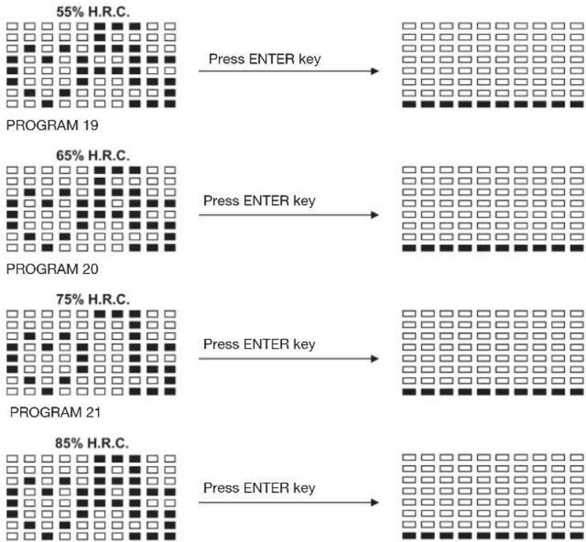
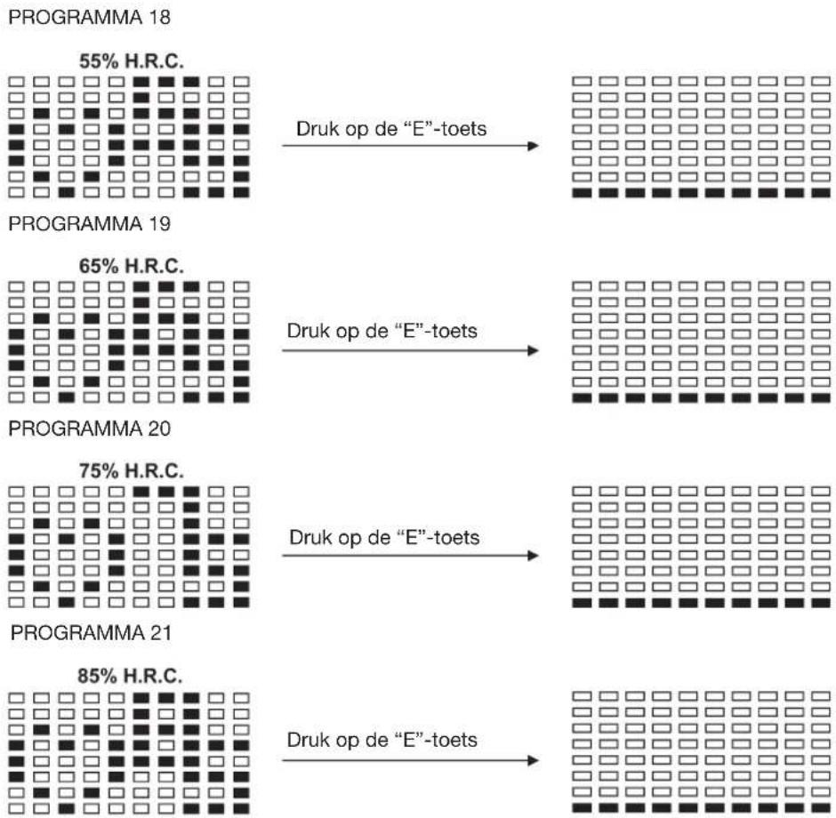
Heart Rate Control Program:
55% H.R.C., 65% H.R.C., 75% H.R.C., 85% H.R.C., Target H.R.C.
Program 18 to Program 22 is the Heart Rate Control Programs and Program 22 is the Target Heart Rate Control program.
Program 18 is the 55% Max H.R.C. -- Target H.R. = (220 - AGE) x 55%
Program 19 is the 65% Max H.R.C. - - Target H.R. = (220 - AGE) x 65%
Program 20 is the 75% Max H.R.C. -- Target H.R. = (220 - AGE) x 75%
Program 21 is the 85% Max H.R.C. -- Target H.R. = (220 - AGE) x 85% Program 22 is the Target H.R.C. -- Workout by your target heart rate value.
Users can exercise according to your desired Heart Rate program by setting your AGE, TIME, DISTANCE, CALORIES or TARGET PULSE. In these programs, the computer will adjust the resistance level according to the heart rate detected. For example, the resistance level may increase every 20 seconds while the heart rate detected is lower than the TARGET H.R..
Operations:
- Use UP/DOWN keys to select one of the heart rate control program from P18 to P22.
- Press the ENTER key to enter your workout program
- The AGE will flash at P18 to P21 programs and you can press UP or DOWN keys to set your AGE. The default age is 35.
- At program 22, the TARGET PULSE will flash and you can press UP or DOWN keys to set your TARGET PULSE between 80 to 180. The default TARGET PULSE is 120.
- The TIME will flash and you can press UP or DOWN keys to set your exercise TIME. Press ENTER key to confirm your desired TIME.
- The DISTANCE will flash and you can press UP or DOWN keys to set your target DISTANCE. Press ENTER key to confirm your desired DISTANCE.
- The CALORIES will flash and you can press UP or DOWN keys to set your exercise CALORIES. Press ENTER key to confirm your desired CALORIES.
- Press the START/STOP key to begin exercise.
Pulse Rate:
The whole set of heart rate detector include 2 sensors each side. Each sensor has 2 pieces of metal parts. The correct way to get detected is to gently hold both metal parts each hand. With the good signals picked up by the computer, the heart mark in the HEART RATE/BODY TYPE Display shall flash. (You can also use a pulse belt which is not codified and has got a frequency of 5.0 – 5.5 KHz)
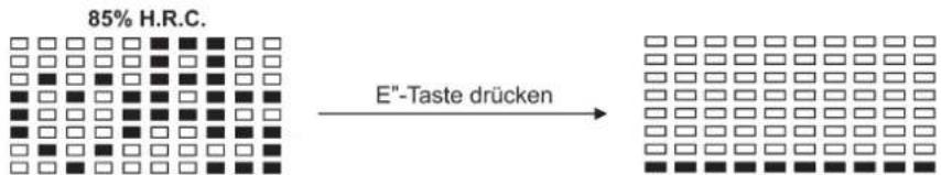
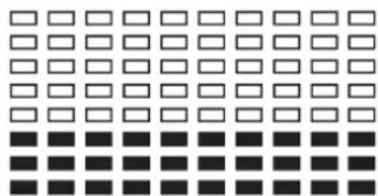
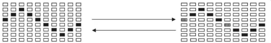
Watt Control Program: Watt Control
Program 23 is a Speed Independent Program. Press ENTER key to set up the values of TARGET WATT, TIME, DISTANCE and CALORIES. During the exercise mode, the level of resistance is not adjustable. For example, the level of resistance may increase while the speed is too slow. Also the level of resistance may decrease while the speed is too fast. As a result, the calculated value of WATT will close to the value of TARGET WATT setup by users.
Operations:
- Use UP or DOWN key to select the WATT CONTROL (P23) program.
- Press ENTER key to enter your workout program.
- The TIME will flash and you can press UP or DOWN key to set your exercise TIME. Press ENTER key to confirm your desired TIME.
-
The DISTANCE will flash and you can press UP or DOWN key to set your target DISTANCE. Press ENTER key to confirm your desired DISTANCE.
-
The WATT will flash and you can press UP or DOWN key to set your target WATT value. Press ENTER key to confirm your target WATT. The default WATT value is 100.
-
The CALORIES will flash and you can press UP or DOWN key to set your exercise CALORIES. Press ENTER key to confirm your desired CALORIES.
- Press the START/STOP key to begin exercise.
NOTE: 1. WATT = TORQUE (KGM) * RPM * 1.03
- In this program, the WATT value will keep constant value. It means that if you peddle quickly, the resistance level will decrease and if you peddle slowly, the resistance level will increase. Always try to keep you in the same watt value.
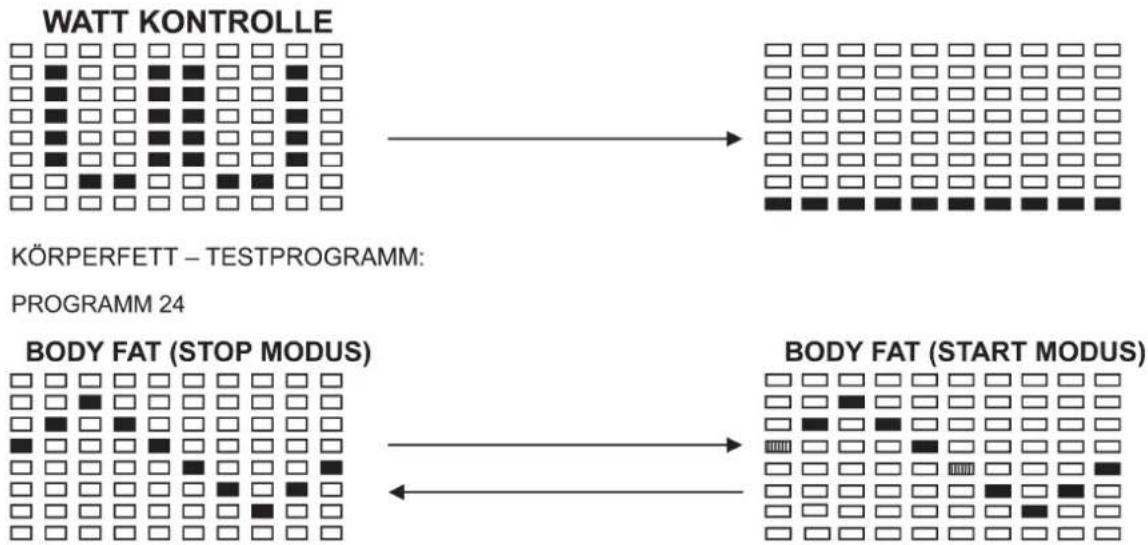
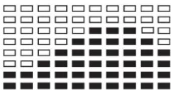
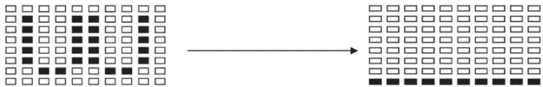
Body Fat Program: Body Fat
Program 24 is a special program design to calculate users' body fat ratio and to offer a specific loading profile for users. There are 3 body types divided according to the FAT% calculated.
Type1: BODY FAT% > 27
Type2: 27 ≥ BODY FAT% ≥ 20
Type3: BODY FAT % < 20
The computer will show the test results of FAT PERCENT, BMI and BMR.
Operations:
- Use UP/DOWN keys to select the BODY FAT (P24) program.
- Press the ENTER key to enter your workout program.
- The HEIGHT will flash and you can press UP or DOWN keys to set your HEIGHT. Press ENTER key to confirm your HEIGHT. The default HEIGHT is 170cm or 5'07" (5feet 7 inches).
- The WEIGHT will flash and you can press UP or DOWN keys to set your WEIGHT. Press ENTER key to confirm your WEIGHT. The default WEIGHT is 70kgs or 155lbs.
- The GENDER will flash and you can press UP or DOWN keys to select your sex. Number 1 means man and number 0 means female. Press ENTER key to confirm your Gender. The default sex is 1 (MAN).
- The AGE will flash and you can press UP or DOWN keys to set your AGE. Press ENTER key to confirm your AGE. The default AGE is 35.
- Press the START/STOP key to begin body fat measurement. If the window show E on the window, please make sure your hands are attached well on the grips or the chest belt is touch well on your body. Then press the START/STOP key again to begin body fat measurement.
- After finished your measurement, the computer will show the values of BMR, BMI and FAT PERCENT on the LCD display. Furthermore, the computer will show your own exercise profile for your body type.
- Press START/STOP key to begin exercise.
Operation guide:
1. Sleep Mode:
The computer will enter the sleep mode when there is no signal input and no keys be pressed after 4 minutes. You can press any key to wake up the computer.
- BMI (Body Mass Index): BMI is a measure of body fat based on height and weight that applies to both adult men and women.
- BMR (Basal Metabolic Rate): Your Basal Metabolic Rate (BMR) shows the number of calories your body needs to operate. This doesn't account for any activity, it's simply the energy needed to sustain a heartbeat, breathing and normal body temperature. It measures the body at rest, not sleep, at room temperature.
Error Message:
E1 (ERROR 1):
Normal state: During workout, when the monitor did not get the count signal from the gear motor more than 4 seconds and check under successive 3 times then the LCD will show E1.
Power on state: The gear motor will return to zero automatically, when the signal of motor cannot be detected for more than 4 seconds then the gear motor's driver will be cut off immediately and show the E1 on the LCD display. All the other digital and function mark are blank, and the output signals are cut off also.
E2 (ERROR 2): When the monitor read the memory data, if the I.D. code is not correct or the memory IC damages then the monitor will show E2 immediately at power on.
E3 (ERROR 3): After 4 seconds by start mode, the computer detects the faulty motor did not leave the zero point then the LCD bar displays "E3".
Technical data of the current adapter
- Available for Input: 230V/50Hz or 60Hz Output: 6V AC/0.5A type: AHEAD, JAD-0600500E
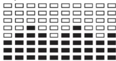
LCD Workout Graphics
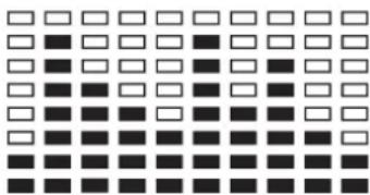
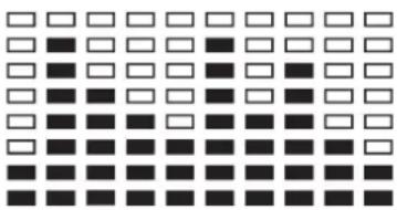
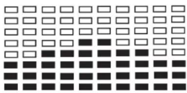
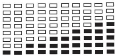
PRESET PROGRAM PROFILES:
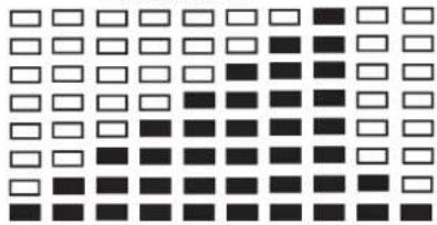
PRECIPICE
natural_image
Grid of black squares with varying shades and borders, no text or symbols presentUSER SETTING PRoGRAM
PROGRAM 14
flowchart
graph TD
    A["USER 1"] --> B["PROGRAM 15"]
    C["USER 2"] --> D["PROGRAM 16"]
    E["USER 3"] --> F["PROGRAM 17"]
    G["USER 4"] --> H["PROGRAM 17"]
HEART FREQUENZY-
PRoGRAM PRoFILE
PROGRAM 18
flowchart
graph TD
    A["55% H.R.C."] -->|Press ENTER key| B["65% H.R.C."]
    B -->|Press ENTER key| C["75% H.R.C."]
    C -->|Press ENTER key| D["85% H.R.C."]
PROGRAM 22
ZIEL H.R.C.

WATT CONTROL PROGRAM
PROGRAM 23
WATT CONTROL

flowchart
graph LR
    A["8 rows of squares"] --> B["8 rows of squares"]
    style A fill:#fff,stroke:#000
    style B fill:#fff,stroke:#000
BODY FAT TEST PROGRAMS:
PROGRAM 24
BODY FAT (STOP MODE)

flowchart
graph LR
    A["Grid of squares with black dots"] --> B["Grid of squares with white dots"]
    B --> C["Arrow pointing right"]
BODY FAT (START MODE)
One of the Following Six Profiles Will Display Automatically after Measuring Your BODY FAT
Training instructions
You must consider the following factors in determining the amount of training effort required in order to attain tangible physical and health benefits:
1. Intensity:
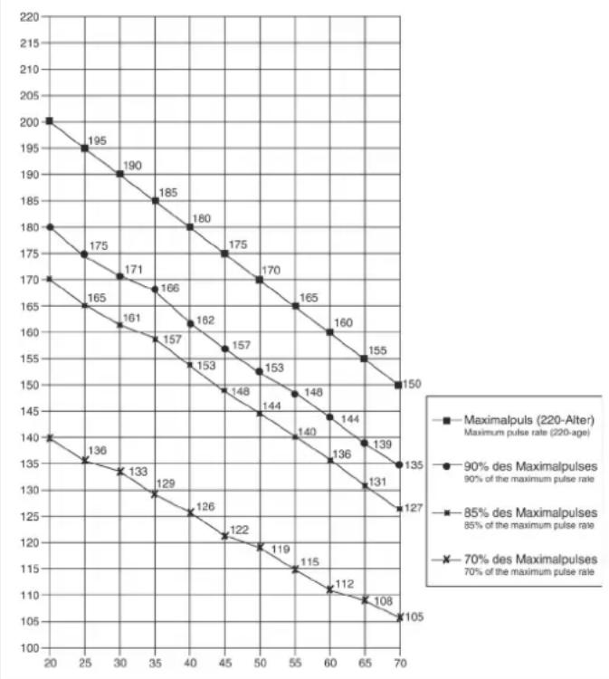
The level of physical exertion in training must exceed the level of normal exertion without reaching the point of breathlessness and / or exhaustion. A suitable guideline for effective training can be taken from the pulse rate. During training this should rise to the region of between 70% to 85% of the maximum pulse rate (see the table and formular for determination and calculation of this).
During the first weeks, the pulse rate should remain at the lower end of this region, at around 70% of the maximum pulse rate. In the course of the following weeks and months, the pulse rate should be slowly raised to the upper limit of 85% of the maximum pulse rate. The better the physical condition of the person doing the exercise, the more the level of training should be encreased to remain in the region of between 70% to 85% of the maximum pulse rate. This should be done by lengthening the time for the training and / or encreasing the level of difficulty.
If the pulse rate is not shown on the computer display or if for safety reasons you wish to check your pulse rate, which could have been displayed wrongly due to error in use, etc., you can do the following:
a. Pulse rate measurement in the conventional way (feeling the pulse at the wrist, for example, and counting the number of beats in one minute).
b. Pulse rate measurement with a suitable specialised device (available from dealers specialising in health-related equipment).
2.Frequency
Most experts recommend a combination of health-conscious nutrition, which must be determined on the basis of your training goal, and physical training three times a week. A normal adult must train twice a week to maintain his current level of condition. At least three training sessions a week are required to improve one's condition and reduce one's weight. Of course the ideal frequency of training is five sessions a week.
3. Planning the training
Each training session should consist of three phases: the warm-up phase, the training phase, and the cool-down phase. The body temperature and oxygen intake should be raised slowly in the warm-up phase. This can be done with gymnastic exercises lasting five to ten minutes.
Then the actual training (training phase) should begin. The training exertion should be relatively low for the first few minutes and then raised over a period of 15 to 30 minutes such that the pulse rate reaches the region of between 70% to 85% of the maximum pulse rate. In order to support the circulation after the training phase and to prevent aching or strained muscles later, it is necessary to follow the training phase with a cool-down phase. This should be consist of stretching exercises and / or light gymnastic exercises for a period of five to ten minutes.
4. Motivation
The key to a successful program is regular training. You should set a fixed time and place for each day of training and prepare yourself mentally for the training. Only train when you are in the mood for it and always have your goal in view. With continuous training you will be able to see how you are progressing day by day and are approaching your personal training goal bit by bit.
line
| X-axis | Maximalpuls (220-Alter) Maximum pulse rate (220-age) | 90% des Maximalpulses 90% of the maximum pulse rate | 85% des Maximalpulses 85% of the maximum pulse rate | 70% des Maximalpulses 70% of the maximum pulse rate | |---|---|---|---|---| | 20 | 200 | 180 | 170 | 140 | | 25 | 195 | 175 | 165 | 135 | | 30 | 190 | 171 | 161 | 133 | | 35 | 185 | 166 | 157 | 129 | | 40 | 180 | 162 | 153 | 126 | | 45 | 175 | 157 | 148 | 122 | | 50 | 170 | 153 | 144 | 119 | | 55 | 165 | 148 | 140 | 115 | | 60 | 160 | 144 | 136 | 112 | | 65 | 155 | 139 | 131 | 108 | | 70 | 150 | 135 | 127 | 105 |Calculation formula: Maximum pulse rate = 220 - age (220 minus your age)
90% of the maximum pulse rate = (220 - age) x 0.9
85% of the maximum pulse rate = (220 - age) x 0.85
70% of the maximum pulse rate = (220 - age) x 0.7
text_image
Technical diagram of a mechanical assembly with numbered components for identificationEtape n° 2:
text_image
Technical diagram showing a mechanical assembly with numbered components and directional arrows indicating motion or force.Etape n° 3:
text_image
Technical diagram of a mechanical device with numbered components for identificationtext_image
Technical diagram of a stationary exercise machine with numbered components and motion arrows indicating movement paths.text_image
Technical diagram of an stationary exercise machine with numbered components for identification.Etape n° 7:
text_image
Technical diagram of a solar panel assembly with numbered components and a magnified view showing internal structure.Etape n° 8:
text_image
Technical diagram of a stationary exercise machine with numbered components and French text labelsEtape n° 9:
text_image
Technical diagram of an exercise bike with labeled components and a close-up view showing the device's cable assembly.Etape n° 10:
Contrôle
text_image
Christopelt Sport TIME 0:00 STOP 0.0 DISTANCE 0.0 PFE CAL 0.0 0 PULSE 0 PROGRAM 0:1 P 1 = Male 0 = Female Test Kärperfett - START STOP + E EProgramme 18 a 55% Max H.R.C. -
- B.C.V. ou Target H.R. = (220 - AGE) x 55%
Programme 19 a 65% Max H.R.C. -
- B.C.V. ou Target H.R. = (220 - AGE) x 65%
Programme 20 a 75% Max H.R.C. -
- B.C.V. ou Target H.R. = (220 - AGE) x 75%
Programme 21 a 85% Max H.R.C.
- B.C.V. ou Target H.R. = (220 - AGE) x 85%
PROGRAMME 1
MANUELLE
natural_image
Grid of black and white squares with no text or symbolsPROGRAMME 4
RoULER

natural_image
Grid of black and white squares with no text or symbolsPROGRAMME 7
PENTE
natural_image
Grid of black and white squares with no text or symbolsPROGRAMME 10
AU HASARD
natural_image
Grid of black and white squares with no text or symbolsPROGRAMME 13
PRECIPICE

text_image
Grid of black and white squares with varying shades, likely representing a pattern or selection interface.PROGRAMME 2
MARCHEPIEDS

natural_image
Grid of black and white squares with varying shades (no text or symbols)PROGRAMME 5
VALLEE
natural_image
Grid of black and white squares with no text or symbolsPROGRAMME 8
MoNTAGNE

natural_image
Grid of black and white squares with varying shades (no text or symbols)PROGRAMME 11
PLATEAU

natural_image
Grid of black and white squares with no text or symbolsPROGRAMME 3
CoLLINE
natural_image
Grid of black and white squares with no text or symbolsPROGRAMME 6
BRULER LIPoSoMES
natural_image
Grid of black and white squares with no text or symbolsPROGRAMME 9
INTERVALLES

natural_image
Grid of black and white squares with no text or symbolsPROGRAMME 12
FART LEK

natural_image
Grid of alternating black and white squares with no text or symbolsPROGRAMME 14

flowchart
graph LR
    A["USER 1"] --> B["PROGRAMME 15"]
    C["USER 2"] --> D["PROGRAMME 16"]
    E["USER 3"] --> F["PROGRAMME 17"]
    G["USER 4"] --> H["PROGRAMME 17"]
PRoFILS DES PRoGRAMMES DE CONTRÔLE DU BATTEMENT DE CŒUR :
PROGRAMME 18

flowchart
graph TD
    A["55% H.R.C."] --> B["Appuyez sur la touche "E""]
    B --> C["PROGRAMME 19"]
    D["65% H.R.C."] --> E["Appuyez sur la touche "E""]
    E --> F["PROGRAMME 20"]
    G["75% H.R.C."] --> H["Appuyez sur la touche "E""]
    H --> I["PROGRAMME 21"]
    J["85% H.R.C."] --> K["Appuyez sur la touche "E""]
    K --> L["PROGRAMME 22"]
    M["ZIEL H.R.C."] --> N["End"]
PROGRAMME CONTRÔLE DE WATT
PROGRAMME 23
CONTRÔLE WATT

flowchart
graph LR
    A["Grid of squares"] --> B["Grid of squares"]
    style A fill:#f9f,stroke:#333
    style B fill:#bbf,stroke:#333
PROGRAMME DE TEST LIPOSOMES :
PROGRAMME 24
LIPOSOMES (MODE STOP)

flowchart
graph LR
    A["Grid of squares with black and white squares"] --> B["Grid of squares with black and white squares"]
    B --> C["Arrow pointing right"]
natural_image
Grid of black and white squares with no text or symbolsnatural_image
Grid of black and white squares with no text or symbolsnatural_image
Grid of black squares with white borders, no text or symbols presentnatural_image
Grid of black and white squares with no text or symbolsnatural_image
Grid of black squares with white borders, no text or symbols presentnatural_image
Grid of black squares with white borders, no text or symbols presenttext_image
Technical diagram of a mechanical assembly with numbered components for identificationStap 2:
text_image
Technical diagram showing a mechanical assembly with numbered components and directional arrows indicating motion or force.Stap 3:
Montage van de handvatbuis rechts en links
text_image
Technical diagram of a mechanical assembly with numbered components and labeled parts A and BStap 4: Montage van de handvatbeugel
text_image
Technical diagram of a mechanical device with numbered components for identificationtext_image
Technical diagram of a stationary exercise machine with numbered components and motion arrows indicating movement paths.text_image
Technical diagram of a stationary exercise machine with numbered components for identification.text_image
Technical diagram of a solar panel assembly with numbered components and a cross-sectional viewtext_image
Technical diagram of a two-wheeled exercise bike with numbered components and instructional text on the left.text_image
Technical diagram of an exercise bike with labeled components and a close-up view of the device's internal structure.Hartslag Controle ('H.R.C.') Programma: 55% H.R.C., 65% H.R.C., 75% H.R.C., 85% H.R.C., Doel H.R.C.
Bij Programma 18 is de 55% Max H.R.C. -
- Doel Hartslag = (220 - LEEFTIJD) x 55%
Bij Programma 19 is de 65% Max H.R.C. -
- Doel Hartslag = (220 - LEEFTIJD) x 65%
Bij Programma 20 is de 75% Max H.R.C.
- Doel Hartslag = (220 - LEEFTIJD) x 75%
Bij Programma 21 is de 85% Max H.R.C. -
- Doel Hartslag = (220 - LEEFTIJD) x 85%
Bij Programma 22 is de Target H.R.C. -
E1 (FOUT of 'ERROR' 1):
natural_image
Grid of black and white squares with no text or symbolsPROGRAMMA 4
RoLLEND

natural_image
Grid of black and white squares with no text or symbolsPROGRAMMA 7
HELLING

natural_image
Grid of black squares with varying shades of gray, no text or symbols presentPROGRAMMA 10
RANDoM
natural_image
Grid of black and white squares with no text or symbolsPROGRAMMA 13
RoTSEN

natural_image
Grid of black and white squares with no text or symbolsPROGRAMMA 2
TRAPPEN

natural_image
Grid of white and black squares with varying shades (no text or symbols)PROGRAMMA 5
VALLEI
natural_image
Grid of black and white squares with no text or symbolsPROGRAMMA 8
BERG
natural_image
Grid of black and white squares with no text or symbolsPROGRAMMA 11
PLATEAU
natural_image
Grid of black and white squares with no text or symbolsPROGRAMMA 3
HEUVEL
natural_image
Grid of alternating black and white squares with no text or symbolsPROGRAMMA 6
VETVERBRANDING

natural_image
Grid of white and black squares with no text or symbolsPROGRAMMA 9
INTERVALLEN

natural_image
Grid of alternating black and white squares with no text or symbolsPROGRAMMA 12
FART LEK

natural_image
Grid of black and white squares with no text or symbols
flowchart
graph TD
    A["PROGRAMMA 14"] --> B["USER 1"]
    B --> C["Programma 15"]
    C --> D["USER 2"]
    D --> E["PROGRAMMA 16"]
    E --> F["USER 3"]
    F --> G["PROGRAMMA 17"]
    G --> H["USER 4"]
HARTSLAGPRoGRAMMA-PRoFIELEN:
flowchart
graph TD
    A["PROGRAMMA 18"] --> B["55% H.R.C."]
    B --> C["Druk op de "E"-toets"]
    C --> D["PROGRAMMA 19"]
    D --> E["65% H.R.C."]
    E --> F["Druk op de "E"-toets"]
    F --> G["PROGRAMMA 20"]
    G --> H["75% H.R.C."]
    H --> I["Druk op de "E"-toets"]
    I --> J["PROGRAMMA 21"]
    J --> K["85% H.R.C."]
    K --> L["Druk op de "E"-toets"]
PROGRAMMA 22
ZIEL H.R.C.
WATTCONTROLE PROGRAMMA
PROGRAMMA 23
WATT CONTROL
text_image
Diagram showing transformation from a grid of squares to a grid of squares, with an arrow indicating the process.VETVERBRANDING TESTPROGRAMMA:
PROGRAMMA 24
BODY FAT (STOP MODE)
flowchart
graph LR
    A["Grid of squares with black dots"] --> B["Grid of squares with white dots"]
    B --> C["Arrow pointing right"]
BODY FAT (START MODE)
natural_image
Grid of black squares with white borders, no text or symbols presentnatural_image
Grid of black squares with varying shades and borders, no text or symbols presentnatural_image
Grid of black and white squares with no text or symbolsnatural_image
Grid of black and white squares with no text or symbolsnatural_image
Grid of black and white squares with no text or symbolsnatural_image
Grid of black and white squares with no text or symbols3. Planning van de training
text_image
Technical diagram of a mechanical assembly with numbered components for identificationWar 2:
text_image
Technical diagram showing a mechanical assembly with numbered components and directional arrows indicating motion or force.War 3:
text_image
Technical diagram of a mechanical device with numbered components for identificationtext_image
Technical diagram of a stationary exercise machine with numbered components and motion arrows indicating movement paths.text_image
Technical diagram of an stationary exercise machine with numbered components for identification.text_image
Technical diagram of a solar panel assembly with numbered components and a cross-sectional viewtext_image
Technical diagram of an exercise bike with labeled components and a close-up view showing the device's cable connection.War 10: Контроль
natural_image
Grid of 16 squares with varying shades of gray and black, no text or symbols presentПРОГРАММА 4
Вверх-вниз
natural_image
Grid of black and white squares with no text or symbolsПРОГРАММА 7
Рампа

natural_image
Grid of black and white squares with no text or symbolsПРОГРАММА 10
Случайная
natural_image
Grid of black and white squares with no text or symbolsПРОГРАММА 13
Крутой подъем
natural_image
Grid of black and white squares with no text or symbolsПРОГРАММА 2
Лестница
natural_image
Grid of white and black squares with varying shades (no text or symbols)ПРОГРАММА 5
Ущелье
natural_image
Grid of black and white squares with no text or symbolsПРОГРАММА 8
Гора
natural_image
Grid of black and white squares with no text or symbolsПРОГРАММА 11
Плоскогорье
natural_image
Grid of black and white squares with no text or symbolsПРОГРАММА 3
Холм

natural_image
Grid of black and white squares with no text or symbolsПРОГРАММА 6
Сжигание жира

natural_image
Grid of black and white squares with no text or symbolsПРОГРАММА 9
Интервал

natural_image
Grid of black and white squares with no text or symbolsПРОГРАММА 12
Смена

natural_image
Grid of black and white squares on a white background, no text or symbols presentПРОГРАММА 14
flowchart
graph LR
    A["USER 1"] --> B["PROGRAMMA 15"]
    C["USER 2"] --> D["PROGRAMMA 16"]
    E["USER 3"] --> F["PROGRAMMA 17"]
    G["USER 4"] --> H["PROGRAMMA 17"]
text_image
Diagram showing transformation of a grid of squares into a grid of squares, with an arrow indicating the process.flowchart
graph LR
    A["BoDY FAT (SToP MoDE)"] --> B["BoDY FAT (START MoDE)"]
    B --> C["Grid of squares with varying fill patterns"]
    style A fill:#f9f,stroke:#333
    style B fill:#bbf,stroke:#333
text_image
top Sports© by Top-Sports Gilles GmbH D-42551 Velbert (Germany)
Service:
Tel.: +49 (0)2051/6067-0
Fax: +49 (0)2051/6067-44