AZ4130 - Alarm system ABUS - Free user manual and instructions
Find the device manual for free AZ4130 ABUS in PDF.
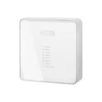
| Product type | Wired expansion module for alarm system |
| Brand | Abus |
| Model | AZ4130 |
| Number of zones | 8 programmable wired zones |
| Anti-tamper monitoring | Yes, integrated |
| Connection | 4-wire bus |
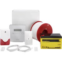
| Compatibility | TERXON M / MX |
| Dimensions (L x H x D) | 220 x 135 x 45 mm |
| Weight | 330 g |
| Power supply | 12 V DC |
| Power consumption | 30 mA max. at 12 V DC |
| Mounting | Wall mounting, using screws and wall plugs |
| Detection type | NC (Normally Closed) or DEOL (Double End of Line) with resistors |
| Maintenance and cleaning | Clean with a dry, non-abrasive cloth |
| Security | Anti-tamper on each zone and housing |
| Spare parts and repairability | Contact ABUS customer service for parts |
| Operating temperature | 0 °C to 40 °C (estimated) |
| Protection rating | IP30 (estimated for indoor use) |
Frequently Asked Questions - AZ4130 ABUS
User questions about AZ4130 ABUS
0 question about this device. Answer the ones you know or ask your own.
Ask a new question about this device
Download the instructions for your Alarm system in PDF format for free! Find your manual AZ4130 - ABUS and take your electronic device back in hand. On this page are published all the documents necessary for the use of your device. AZ4130 by ABUS.
USER MANUAL AZ4130 ABUS
8-Zone Hardwired Expander Installation Instructions (UK) 5
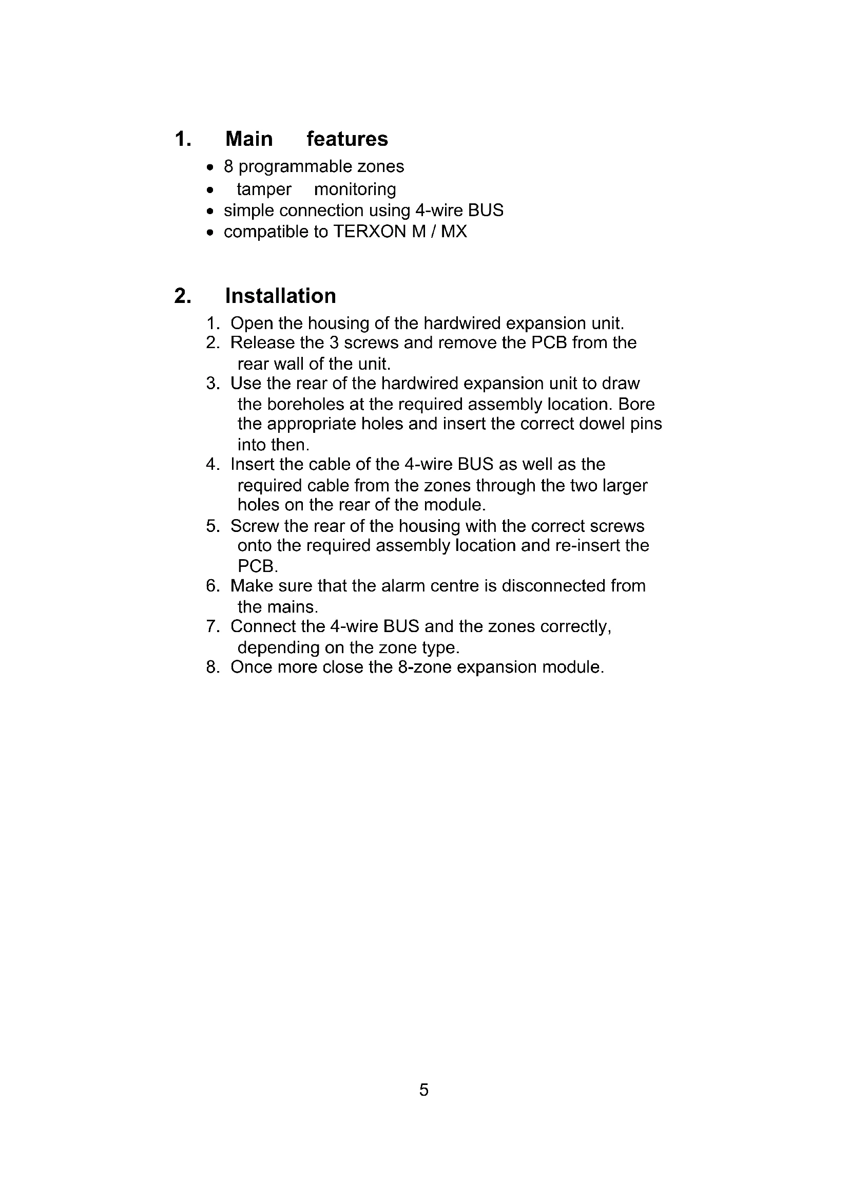
8 programmable zones
tamper monitoring
- simple connection using 4-wire BUS
compatible to TERXON M / MX
2. Installation
- Open the housing of the hardwired expansion unit.
- Release the 3 screws and remove the PCB from the rear wall of the unit.
- Use the rear of the hardwired expansion unit to draw the boreholes at the required assembly location. Bore the appropriate holes and insert the correct dowel pins into then.
- Insert the cable of the 4-wire BUS as well as the required cable from the zones through the two larger holes on the rear of the module.
- Screw the rear of the housing with the correct screws onto the required assembly location and re-insert the PCB.
- Make sure that the alarm centre is disconnected from the mains.
- Connect the 4-wire BUS and the zones correctly, depending on the zone type.
- Once more close the 8-zone expansion module.
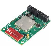
3. Description of components
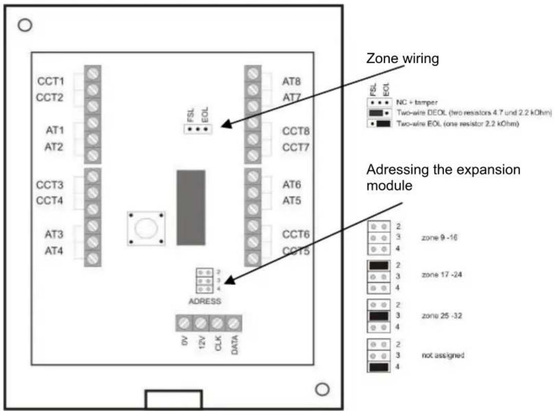
The 4 wires from the communication bus of the alarm panel are connected at the data BUS as described in the installation instructions of the alarm panel. Additional modules are connected in parallel at this BUS. The zone ranges are differentiated by the addressing of the modules.
You must also set the type of zone wiring. The zone types from the alarm centre and the expansion modules may be different.
NOTE:
When putting into operation, the alarm centre automatically learns which zones are additionally assigned by the expansion module.
4. Zone wiring
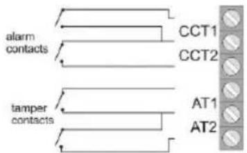
4.1 NC+SABO
The respective contact closes the line. No additional resistors are inserted in the line.
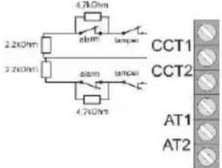
4.2 DEOL
There is a simultaneous tampering (sabotage) and alarm monitoring for every detector circuit (CCT). Different resistors are required.
4.3 EOL
This circuit is like in the central not used.
5. Technical data
| Zones | 8 wired zones | Dimensions (HxWxD) | 220x135x45 mm |
| Voltage supply | 12 V DC | Weight | 330 g |
| Power consumption | max. 30 mA at 12 V DC |