
HomeTec Pro FCA3000 - Alarm system ABUS - Free user manual and instructions
Find the device manual for free HomeTec Pro FCA3000 ABUS in PDF.
| Product type | Motorized alarm system for windows and French doors |
| Use | Dry indoor, windows/French doors opening inward, 7 mm square, distance to lock ≥ 30 mm, frame width ≥ 60 mm |
| Main components | Wireless window mechanism, wireless remote control (CFF3000), wireless keypad (CFT3000) (remote control and keypad not included) |
| Power supply | Alkaline or rechargeable batteries (Eneloop BK-3MCCE type recommended) |
| Operating temperature | 0 °C to +40 °C |
| Radio frequency | Unspecified frequency, maximum transmission power < 10 dBm |
| Maximum number of transmitters | 9 (remote controls and keypads) |
| Main functions | Motorized locking/unlocking, comfort function (FCA3000), security function with two locking bars (FSA3550), integrated anti-intrusion alarm |
| Anti-intrusion alarm | Triggered if an attempt is made to open the handle while the cylinder is engaged, sound power ≈ 110 dBA |
| Tilt function | Optional (expert menu), allows switching from tilt position to 'open' with manual assistance |
| Audible signals | Configurable (expert menu): in all end positions, only motorized locking, or none (except alarms and key presses) |
| Locking torque | Configurable: approximately 6 Nm (limited) or approximately 8 Nm (maximum) |
| Low battery indicator | 5 short beeps before movement or cylinder engagement |
| Break-in attempt indicator | 5 long beeps after movement or cylinder depression |
| Mechanical safety | Manual unlocking possible from inside via the handle in case of emergency or power failure |
| Magnet mounting | Must be programmed first (menu 6 then 8); magnet supplied with spacers, requires 20 cm distance from medical implants |
| Glass break detector compatibility | Possible (GBM, see page 57 of the manual) |
| Maintenance | Check the smoothness of the window/French door; replace batteries with new alkaline or fully charged rechargeable batteries |
| Recycling | Dispose of according to WEEE Directive 2002/96/EC; contact the local authority or retailer for collection points |
Frequently Asked Questions - HomeTec Pro FCA3000 ABUS
User questions about HomeTec Pro FCA3000 ABUS
0 question about this device. Answer the ones you know or ask your own.
Ask a new question about this device
Download the instructions for your Alarm system in PDF format for free! Find your manual HomeTec Pro FCA3000 - ABUS and take your electronic device back in hand. On this page are published all the documents necessary for the use of your device. HomeTec Pro FCA3000 by ABUS.
USER MANUAL HomeTec Pro FCA3000 ABUS
HomeTec Pro™ FCA3000 / FSA3550

DE Funk-Fenstercomfortantrieb / Funk-Fenstersicherheitsantrieb
GB Wireless window comfort actuator / Safety wireless window actuator
FR Mécanisme de fenêtre radiocommandé / Mécanisme de fenêtre de sécurité radiocommandé
NL Draadloze venstercomfortaandrijving / Draadloze vensterveiligheidsaandrijving
IT Attuatore radio comfort finestra / Attuatore radio sicurezza finestra
ES Accionamiento de ventana confort por radio / Accionamiento de seguridad de ventana por radio


FCA3000 FSA3550
natural_image
Line drawing of a door handle assembly with handle and clasp (no text or symbols)
natural_image
Line drawing of a rectangular door frame with a handle and side lock (no text or symbols)DE Inhalt
GB Content
FR Teneur
NL Inhoud
IT Contenuto
ES Conteúdo
FCA3000 / FSA3550 is a retrofit system for motor-operated locking and unlocking of windows and patio doors that open inwards with 7 mm square shaft and a backset of at least 30 mm. The window sash width must be at least 60 mm.
In addition to the convenience function of the FCA3000, the FSA3550 also offers a window locking function with two locking bars. The system comprises three components: the wireless window actuator, the wireless remote control and the wireless keypad. In order to use the wireless window actuator as intended, you require a HomeTec Pro remote control or keypad. The remote control can also be used in combination with the keypad, as can multiple remote controls. For FSA3550, a matching set of locking bars (page 7) is also required.
FR
In addition, the FCA3000 / FSA 3550 offers a break-in monitoring function. With the window closed and the pressure cylinder pressed in, attempts to force the window result in the integrated acoustic alarm being triggered with a sound pressure level of approx. 110 dBA. Motorised opening and closing of the FCA3000 / FSA3550 is also possible with the cylinder pushed in.
Before fitting, please check the adjustment of your window / patio door. Ensure that the window is in perfect condition and operates easily. Windows / patio doors that are not in perfect condition or are difficult to operate lead to reduced battery life!
The product is intended only for operation in dry internal rooms. Like all technical devices, the FCA3000 /
FSA3550 can fail for various reasons.
It must always be possible to operate one main access point to the property from outside properly. In an emergency or panic situation, in the event of a fault or if the battery is flat, the window / patio door can be unlocked mechanically from inside by hand, using the window handle.
Contact a specialist company if necessary!
Operating temperature range: 0°C to +40°C.
Radio frequency:
868,0 MHz - 868,6 MHz
Maximum radiated transmission
power: < 10dBm eirp
868,0 MHz - 868,6 MHz
868,0 MHz - 868,6 MHz
868,0 MHz - 868,6 MHz
natural_image
Technical line drawing of a screwdriver and a ruler (no text or symbols present)as an extra for FSA3550
natural_image
Technical line drawing of a soldering iron, showing its three components: a drill bit, a flat blade, and a pen (no text or symbols present)as an extra for glass break detector
natural_image
Line drawings of two pliers and a tool (no text or symbols)4.
DE Montage FCA3000
GB Installation instructions FCA3000
FR Instructions de montage FCA3000
NL Montageaanwijzing FCA3000
IT Istruzioni di montaggio FCA3000
ES Instrucciones de montaje FCA3000
i
natural_image
Technical line drawing of a square-framed window with internal diagonal lines and mounting holes (no text or symbols)DIN R
natural_image
Line drawing of a rectangular frame with internal lines and mounting holes (no text or symbols)DIN L
Anleitung zeigt die Montage an einem Fenster DIN rechts (R). Bei DIN linken Fenstern zu beachtende Abweichungen sind bei den entsprechenden Montageschritten durch die Abbildung „Fenster DIN links“ (L) gekennzeichnet.
The instruction shows the assembly on a right-hand window (R). The differences to be noted for left-hand windows are marked with the corresponding fitting steps on the diagram „left-hand window“ (L).
FR La notice de montage illustre le montage sur une fenêtre à droite (R). Les divergences dont il faut tenir compte pour les fenêtres à gauches sont signalées dans les étapes de montage correspondantes avec le schéma „fenêtre à gauche“ (L).
Instructie beschrijft de montage op een raam DIN rechts (R). Afwijkingen voor DIN-linkse ramen zijn bij de betreffende instructies aangegeven door de afbeelding „raam DIN links" (L).
⑪ Le istruzioni mostrano il montaggio ad una finestra destra (R). Le differenze da osservare per finestre sinistre sono indicate dalla figura „finestra sinistra“ (L) a margine delle relative fasi di montaggio.
Las instrucciones ilustran la instalación en una ventana DIN derecha (R). Las desviaciones a tener en cuenta en ventanas izquierdas se indican en los pasos de montaje correspondientes por medio de la figura „Ventana DIN izquierda“ (L).
4.1
DE Demontage vorhandener Griff
GB Dismantling existing handle
FR Démontage poignée existante
NL Demontage bestaande
greep
IT Smontaggio maniglia essistente
ES Desmontaje mango existente
4.1a


DE Grundplatte und Vierkant zueinander spannungsfrei im 90°-Winkel montieren und Schrauben nur von Hand andrehen!
GB Fit base plate and square shaft at 90° to one another without tension and tighten by hand only!
FR Montez la plaque de base et le carré l'un à l'autre dans tension dans un angle de 90° et vissez en serrant uniquement à la main!
NL Monteer de grondplaat en de vierkante stift zonder spanning in een hoek van 90° en schroef ze met de hand vast!
IT Montare il fondello e il perno quadro a 90° fra loro senza tensione e avvitare le viti solo a mano!
¡Montar la placa base y el cuadrado entre sí sin tensión y en un ángulo de 90° y atornillar los tornillos a mano!
4.3
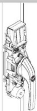
DE Montage der Griffeinheit
GB Fitting the handle unit
FR Montage de l'unité de poignée
NL Monteren van de greep
IT Montaggio dell'unità maniglia
ES Montaje de la manilla
4.3a

4.3b

4.3b

4.3 d4
natural_image
Technical line drawing of a mechanical device with no visible text or symbols4.4
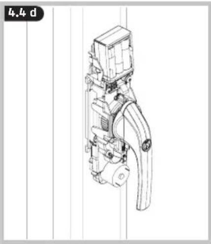
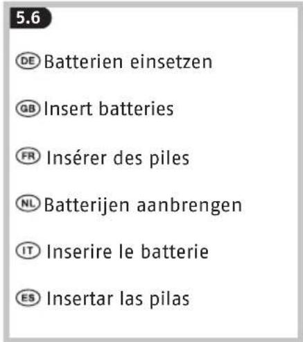
DE Batterien einsetzen
GB Insert batteries
FR Insérer des piles
NL Batterijen aanbrengen
IT Inserire le batterie
ES Insertar las pilas
DE
Batteriehinweise
Battery instructions
When inserting the batteries, ensure the polarity is correct!
Batteries must be kept out of reach of children. Children can put batteries in their mouths and choke. This can cause serious injury. Seek immediate medical attention in this event!
Contact with expired or damaged batteries may cause chemical burns! In these cases, use suitable protective gloves and clean the battery compartment with a dry cloth.
Batteries must not be dismantled, pierced, otherwise damaged, short-circuited, heated or thrown into an open fire (risk of explosion!).
NL
natural_image
Technical line drawing of a mechanical assembly with no visible text or symbols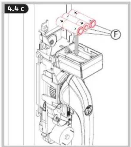
natural_image
Technical line drawing of a mechanical device with no visible text or symbols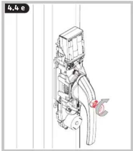
natural_image
Technical line drawing of a mechanical device with pipes and housing (no text or symbols)
GB Manually check that the window handle is functioning. The handle must turn easily. If the handle can only be turned with difficulty, the window fittings, base plate or square shaft may have to be re-adjusted
⑥ The magnet Ⓗ - Ⓛ may only be mounted after programming >> 6 >> 8.
natural_image
Isometric line drawing of a rectangular frame with internal diagonal lines and mounting holes (no text or symbols)DIN R

natural_image
Line drawing of a rectangular frame with a vertical slot and a handle, no text or symbols presentDIN L
Anleitung zeigt die Montage an einem Fenster DIN rechts (R). Bei DIN linken Fenstern zu beachtende Abweichungen sind bei den entsprechenden Montageschritten durch die Abbildung „Fenster DIN links“ (L) gekennzeichnet.
The instruction shows the assembly on a right-hand window (R). The differences to be noted for left hand windows are marked with the corresponding fitting steps on the diagram „left-hand window" (L).
La notice de montage illustre le montage sur une fenêtre à droite (R). Les divergences dont il faut tenir compte pour les fenêtres à gauches sont signalées dans les étapes de montage correspondantes avec le schéma „fenêtre à gauche“ (L).
NL Instructie beschrijft de montage op een raam DIN rechts (R). Afwijkingen voor DIN-linkse ramen zijn bij de betreffende instructies aangegeven door de afbeelding „raam DIN links" (L).
11 Le istruzioni mostrano il montaggio ad una finestra destra (R). Le differenze da osservare per finestre sinistre sono indicate dalla figura „finestra sinistra“ (L) a margine delle relative fasi di montaggio.
Las instrucciones ilustran la instalación en una ventana DIN derecha (R). Las desviaciones a tener en cuenta en ventanas izquierdas se indican en los pasos de montaje correspondientes por medio de la figura „Ventana DIN izquierda“ (L).
D
DE Demontage vorhandener Griff
GB Dismantling existing handle
FR Démontage poignée existante
NL Demontage bestaande
greep
IT Smontaggio maniglia essistente
ES Desmontaje mango existente
5.1 a5.

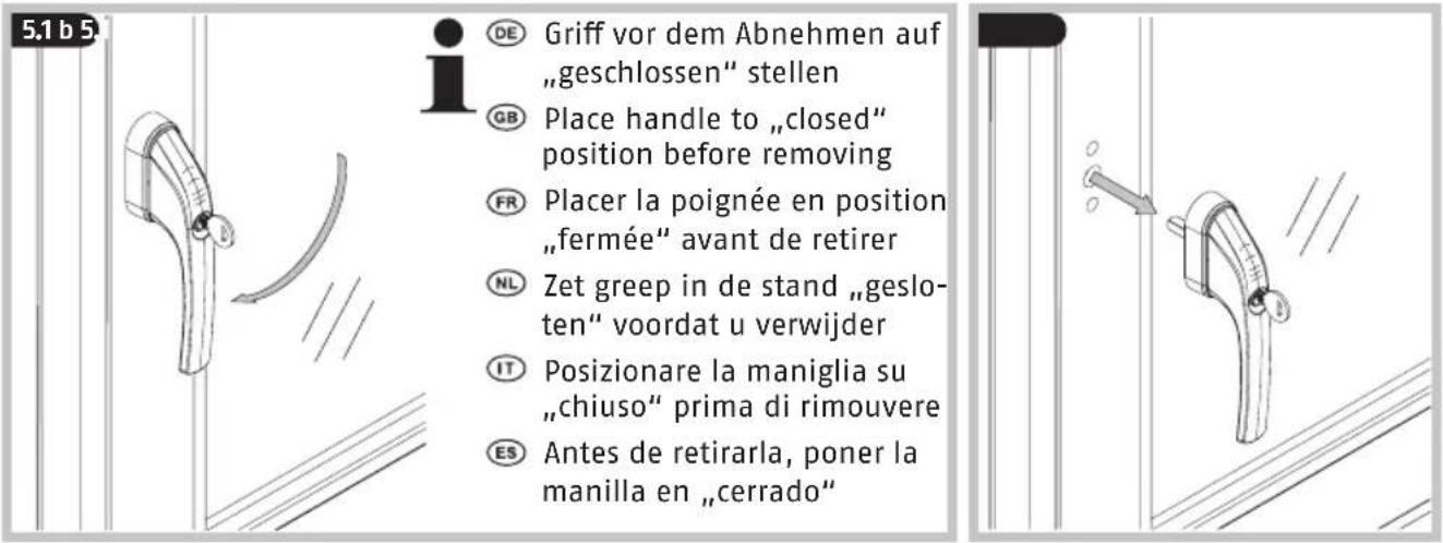
DE Griff vor dem Abnehmen auf „geschlossen“ stellen
GB Place handle to „closed" position before removing
FR Placer la poignée en position „fermée“ avant de retirer
NL Zet greep in de stand „gesloten“ voordat u verwijder
⑪ Posizionare la maniglia su „chiuso“ prima di rimouvere
ES Antes de retirarla, poner la manilla en „cerrado“
5.1d
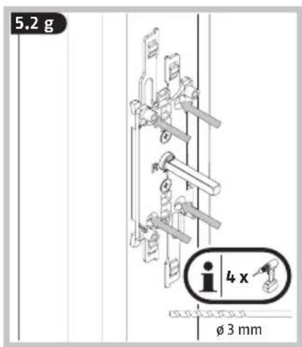
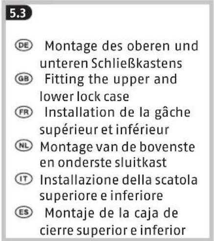
5.2
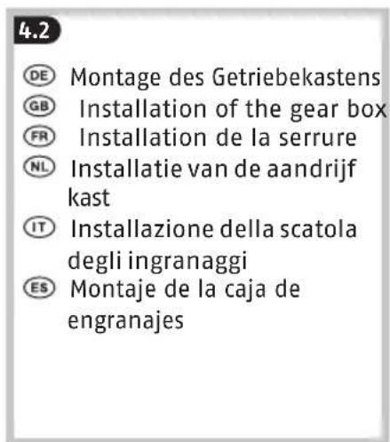
DE Montage des Getriebekastens
GB Installation of the gear box
FR Installation de la serrure
NL Installatie van de aandrijf kast
IT Installazione della scatola degli ingranaggi
ES Montaje de la caja de engranajes


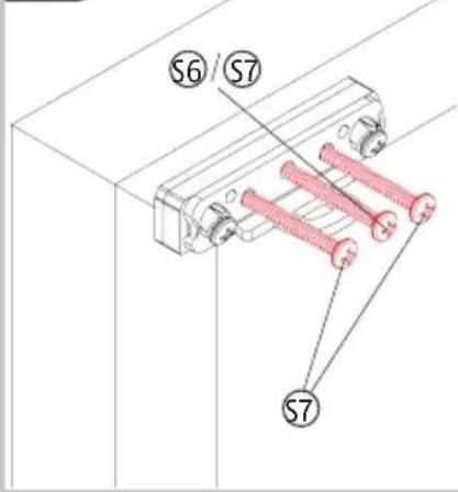
DE Grundplatte und Vierkant zueinander spannungsfrei im 90°-Winkel montieren und Schrauben nur von Hand andrehen!
GB Fit base plate and square shaft at 90° to one another without tension and tighten by hand only!
FR Montez la plaque de base et le carré l'un à l'autre dans tension dans un angle de 90° et vissez en serrant uniquement à la main!
NL Monteer de grondplaat en de vierkante stift zonder spanning in een hoek van 90° en schroef ze met de hand vast!
IT Montare il fondello e il perno quadro a 90° fra loro senza tensione e avvitare le viti solo a mano!
ES ¡Montar la placa base y el cuadrado entre sí sin tensión y en un ángulo de 90° y atornillar los tornillos a mano!


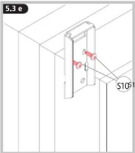
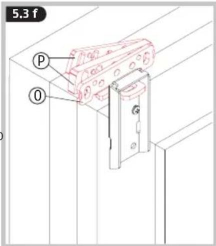


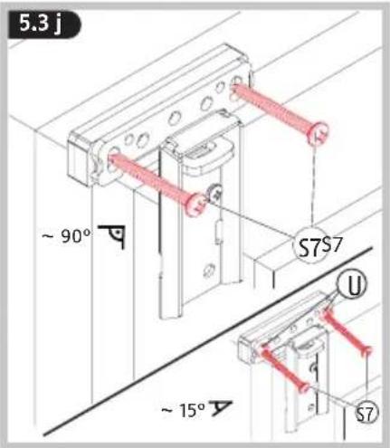


5.3 m
DE Mittlere Schraube ggf. mit ABUS BA / IM100 befestigen
GB If necessary, tighten the middle screw with ABUS BA / IM100
FR Au besoin, serrer la vis centrale avec ABUS BA / IM100
NL Middelste schroef eventueel met ABUS BA / IM100 bevestigen
Se necessario, fissare la vite intermedia con ABUS BA / IM100
ES Dado el caso, fijar el tornillo del centro con ABUS BA/IM100.
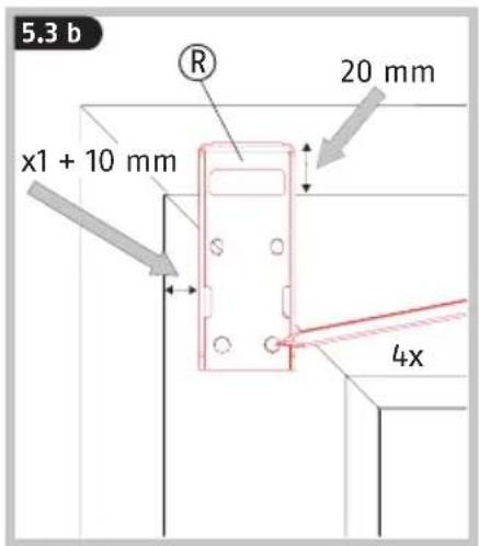
5.3 n
DE 5.3d - 5.3m analog für unteren Schließkasten wiederholen
GB Repeat 5.3d - 5.3m for the bottom strike plate
FR 5.3d - 5.3m de la même manière pour la gâche inférieur
NL 5.3d - 5.3m analoog voor onderste sluitkast herhalen
IT Ripetere i punti 5.3d - 5.3m per la scatola inferiore
ES Repetir 5.3d - 5.3m para la caja de cierre inferior
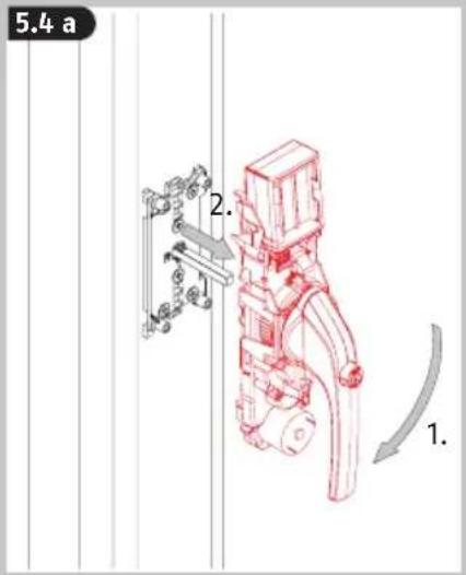
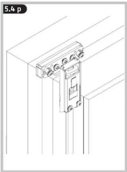
5.4
DE Montage der Riegelstangen
GB Fitting the locking bars
FR Montage des tringles de verrouillage
NL Monteren van de bouten
IT Montaggio delle barre dei chiavistelli
ES Montaje de los pestillos de cierre
5.4 a
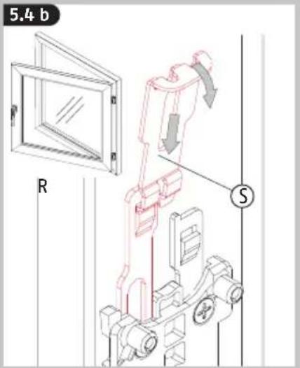
5.4b
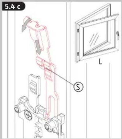
5.4c
5.4d

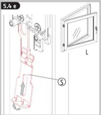
5.4e
5.4f

DE Maß Xr messen von Oberkante R (innen) bis Oberkante S. Von diesem Maß 2 mm abziehen
GB Measure dimension Xr from upper edge R (inside) to upper edge S. Subtract 2 mm from this dimension
FR Mesurer Xr du bord supérieur R (intérieur) jusqu'au bord supérieur S. Retirer 2 mm de cette distance
NL Maat Xr meten van bovenkant R (binnen) tot aan de bovenkant S. Van deze maat 2 mm aftrekken
⑪ Misurare la quota Xr dal bordo superiore R (interno) al bordo superiore S. Da questa quota sottrarre 2 mm
ES Medir la dimensión Xr desde el borde superior R (interior) hasta el borde superior S. Restar 2 mm a esta medida
5.4 g

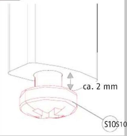
DE Riegelstange an unterem Ende bei Xr - 2 mm absäge
GB Saw off the lock bar at the lower end at Xr - 2 mm
FR Sciez l'extrémité inférieure de la tige de verrouillage de Xr- 2 mm
NL Zaag de grendelstang aan de onderzijde bij Xr-2 mm af
⑪ Segare l'estremità inferiore della barra del catenaccio al punto Xr - 2 mm
ES Cortar el pestillo de cierre en el extremo inferior Xr -2 mm
DE 5.4f - 5.4g analog für untere Riegelstange wiederholen
GB Repeat 5.4f - 5.4g for the lower locking bar
FR Répéter 5.4f - 5.4g pour la tringle inférieure
NL 5.4f - 5.4g analoog voor onderste grendelstang herhalen
IT Ripetere i punti 5.4f - 5.4g per la barra del chiavistello inferiore
ES Repetir 5.4f - 5.4g para la caja de cierre inferior
5.4 i 5
-

natural_image
Technical line drawing of a mechanical assembly with no visible text or symbols
natural_image
Technical line drawing of a mechanical assembly with no visible text or symbols


natural_image
Technical line drawing of a mechanical assembly with no visible text or symbols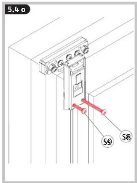
natural_image
Technical line drawing of a mechanical lifting device mounted on a structural frame (no text or symbols)

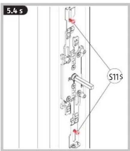
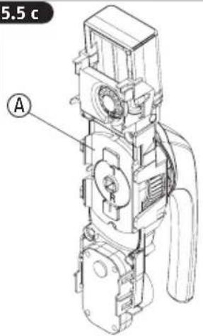
5.5
DE Abdeckungen für die Riegel-
stangen und Griffeinheit
GB Locking bar covers and handle unit
FR Couvercles des tiges de ver-rouillage et unité de poignée
NL Afdek kingen voor de gren-
delstangen en greep
IT Coperture per le barre del catenaccio e unità maniglia
ES Cubiertas para los pestillos de cierre y manilla
5.5 a
5.5 b

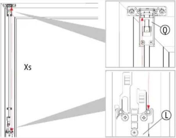
DE Beide Abdeckungen: Maß Xs messen von Oberkante Q bis Oberkante Grundplatte L. Von diesem Maß 75 mm abziehen
GB For both covers: Measure dimension Xs from upper edge Q to upper edge ground plate L. Subtract 75 mm from this dimension
FR Les deux couvercles: Mesurer Xs du bord supérieur Q jusqu'au bord supérieur de la plaque de base L. Retirer 75 mm de cette dimension
NL Beide Afdekkingen: Maat Xs meten van bovenkant Q tot aan de bovenkant van grondplaat L. Van deze maat 75 mm aftrekken
⑪ Due coperture: Misurare la quota Xs dal bordo superiore Q al bordo superiore del fondello L. Da questa quota sottrarre 75 mm
ES Ambas cubiertas: medir Xs desde el borde inferior Q (interior) hasta el borde superior de la placa base L. Restar 75 mm a esta medida
5.5c
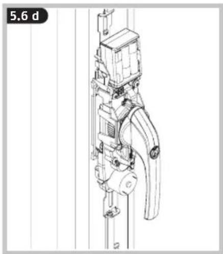
5.5 d

5.5 e


natural_image
Technical line drawing of a mechanical device mounted on a vertical pole, with no visible text or symbols.

natural_image
Technical line drawing of a vertical mechanical structure with a red vertical panel and a small component, no text or symbols present.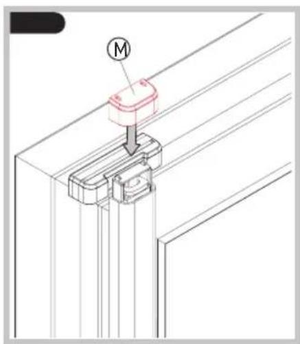
DE
Batteriehinweise
Battery instructions
When inserting the batteries, ensure the polarity is correct!
Batteries must be kept out of reach of children. Children can put batteries in their mouths and choke. This can cause serious injury. Seek immediate medical attention in this event!
Contact with expired or damaged batteries may cause chemical burns! In these cases, use suitable protective gloves and clean the battery compartment with a dry cloth.
Batteries must not be dismantled, pierced, otherwise damaged, short-circuited, heated or thrown into an open fire (risk of explosion!).
NL
natural_image
Technical line drawing of a mechanical assembly with no visible text or symbols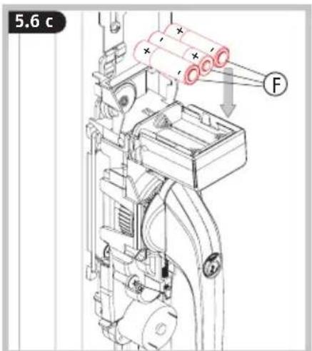
natural_image
Technical line drawing of a mechanical device with no visible text or symbols
natural_image
Technical line drawing of a mechanical assembly with no visible text or symbols
GB Manually check that the window handle is functioning. The handle must turn easily. If the handle can only be turned with difficulty, the window fittings, base plate or square shaft may have to be re-adjusted
The magnet Ⓗ - Ⓚ may only be mounted after programming >> 6 >> 8.
natural_image
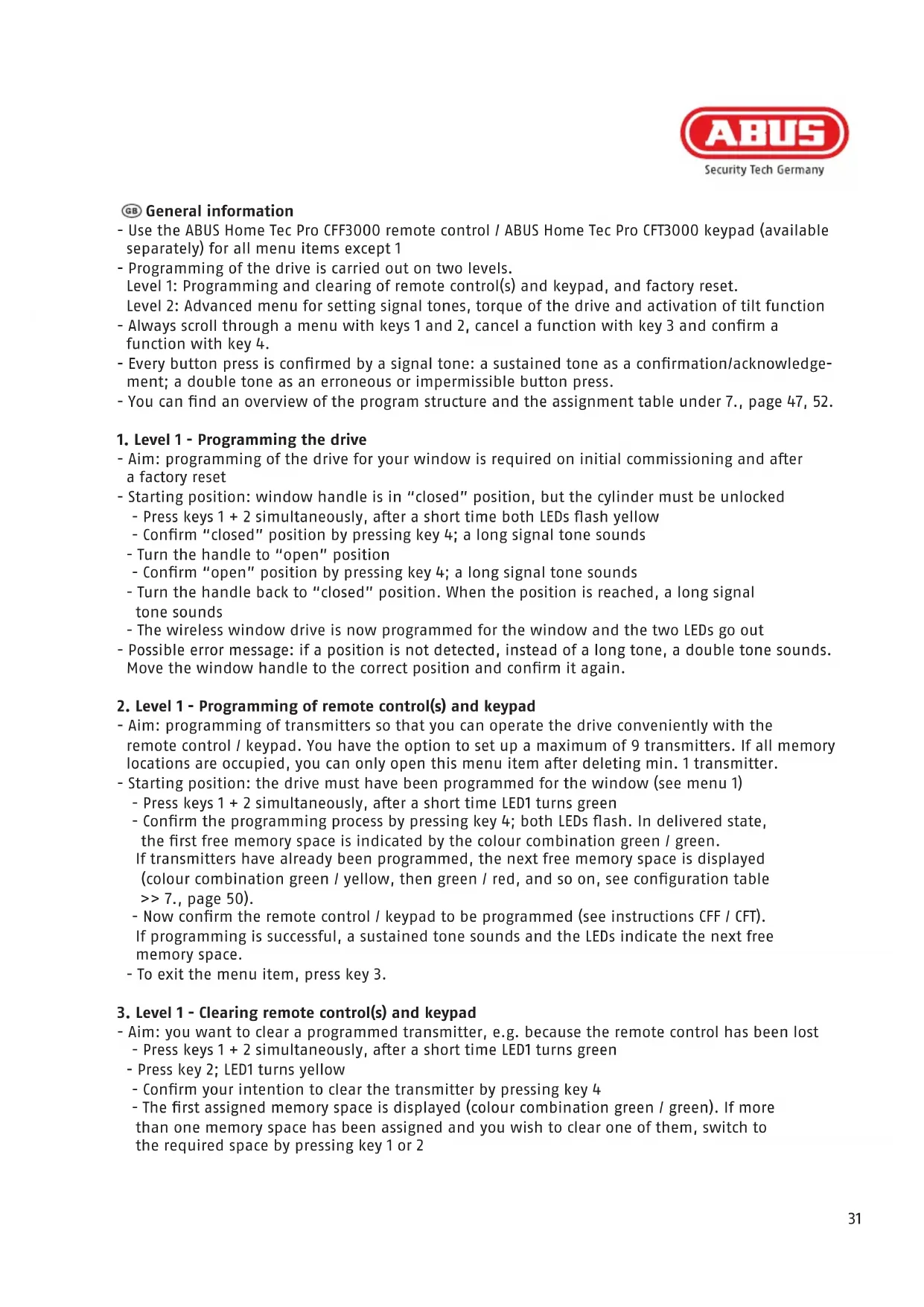
Technical line drawing of a mechanical device with pipes and components (no text or symbols)DE Die folgende Abbildung zeigt die Anordnung der Tasten und LEDs am Antrieb bei abgenommener Abdeckkappe. Die Programmiermöglichkeiten finden Sie auf den Seiten 28-30.
GB The following illustration shows the configuration of the keys and LEDs on the drive with the cover removed. The programming options can be found on pages 31-33.
FR L'illustration suivante montre l'ordre des touches et LED au niveau de l'entraînement lorsque le couvercle est retiré. Les possibilités de programmation sont disponibles aux pages 34-36.
NL Onderstaande afbeelding toont de positie van de knoppen en led's op de aandrijving wanneer het afdekklepje verwijderd is. De programmeermogelijkheden vindt u op pagina's 37-39.
⑪ L'immagine seguente mostra la disposizione dei tasti e dei LED sull'attuatore con coperchio rimosso. Le programmazioni possibili si trovano alle pagine 40-42.
Es La siguiente figura muestra la disposición de las teclas y LED en el accionamiento con la tapa de cubierta retirada. En las páginas 43-45 encontrará las posibilidades de programación.

- Use the ABUS Home Tec Pro CFF3000 remote control / ABUS Home Tec Pro CFT3000 keypad (available separately) for all menu items except 1
- Programming of the drive is carried out on two levels.
Level 1: Programming and clearing of remote control(s) and keypad, and factory reset. Level 2: Advanced menu for setting signal tones, torque of the drive and activation of tilt function
- Always scroll through a menu with keys 1 and 2, cancel a function with key 3 and confirm a function with key 4.
- Every button press is confirmed by a signal tone: a sustained tone as a confirmation/acknowledgement; a double tone as an erroneous or impermissible button press.
- You can find an overview of the program structure and the assignment table under 7., page 47, 52.
1. Level 1 - Programming the drive
- Aim: programming of the drive for your window is required on initial commissioning and after a factory reset
-
Starting position: window handle is in "closed" position, but the cylinder must be unlocked
-
Press keys 1 + 2 simultaneously, after a short time both LEDs flash yellow
- Confirm "closed" position by pressing key 4; a long signal tone sounds
- Turn the handle to "open" position
- Confirm "open" position by pressing key 4; a long signal tone sounds
- Turn the handle back to "closed" position. When the position is reached, a long signal tone sounds
- The wireless window drive is now programmed for the window and the two LEDs go out
- Possible error message: if a position is not detected, instead of a long tone, a double tone sounds. Move the window handle to the correct position and confirm it again.
2. Level 1 - Programming of remote control(s) and keypad
- Aim: programming of transmitters so that you can operate the drive conveniently with the remote control / keypad. You have the option to set up a maximum of 9 transmitters. If all memory locations are occupied, you can only open this menu item after deleting min. 1 transmitter.
- Starting position: the drive must have been programmed for the window (see menu 1)
- Press keys 1 + 2 simultaneously, after a short time LED1 turns green
- Confirm the programming process by pressing key 4; both LEDs flash. In delivered state, the first free memory space is indicated by the colour combination green / green. If transmitters have already been programmed, the next free memory space is displayed (colour combination green / yellow, then green / red, and so on, see configuration table >> 7., page 50).
- Now confirm the remote control / keypad to be programmed (see instructions CFF / CFT). If programming is successful, a sustained tone sounds and the LEDs indicate the next free memory space.
- To exit the menu item, press key 3.
3. Level 1 - Clearing remote control(s) and keypad
- Aim: you want to clear a programmed transmitter, e.g. because the remote control has been lost - Press keys 1 + 2 simultaneously, after a short time LED1 turns green
- Press key 2; LED1 turns yellow
- Confirm your intention to clear the transmitter by pressing key 4
-
The first assigned memory space is displayed (colour combination green / green). If more than one memory space has been assigned and you wish to clear one of them, switch to the required space by pressing key 1 or 2
-
Press and hold key 4 for approx. 2 seconds; both LEDs flash
- Press and hold key 4 for approx. two seconds again and the memory space will be cleared. An acoustic confirmation sounds and the LEDs go out
- To exit the menu item, press key 3
4. Level 1 - Resetting to factory settings (factory reset)
- Aim: you want to clear the drive settings. There are three options to choose from: I.) Clearing the programming for your window and any other settings on the advanced menu (see 5.). II.) Clearing all saved transmitters. III.) Complete factory reset
- Press keys 1 + 2 simultaneously, after a short time LED1 turns green.
- Press key 2 twice in succession; LED1 turns red.
- Confirm your intention to carry out a factory reset by pressing key 4
- LED1 is red, LED2 is green = option I. This position resets the programming process and all settings on the advanced menu
- Pressing key 1 or 2 switches to option II or option III: LED1 is red, LED2 is yellow = option II. This position clears all transmitters (remote controls, keypad).
LED1 is red, LED2 is red = option III. This position triggers a complete factory reset. The drive is then in its delivered condition
- With the LED display required, press and hold key 4 for approx. 2 seconds; both LEDs flash alternately
- Press and hold key 4 again for approx. 2 seconds and the reset is carried out. An acoustic confirmation follows and the LEDs go out.
- To exit the menu item, press key 3
5. Level 2 - Advanced menu settings
The settings on the advanced menu are optional. You can modify the default values for the drive on three submenus: A) Signal tones, B) Torque and C) Tilt function.
To access level 2, first complete the following two steps:
- Press keys 1 + 2 simultaneously, after a short time LED1 turns green.
- Press keys 1 + 2 simultaneously again, after a short time LED1 flashes green.
A) Signal tones (LED 1 flashes green)
- Confirm your intention to change the signal tones by pressing key 4
- Choose the required setting by pressing key 1 or 2:
LED 1 green / LED 2 green: signal tone in all end positions (factory setting)
LED 1 flashes green / LED 2 lights yellow: signal tone on motorised locking
LED 1 flashes green / LED 2 lights red: no signal tones*
i * Alarm signals for required battery change, overload of the drive and magnetic displacement (attempt at burglary) and key tones for the drive cannot be switched off!
B) Torque
- Switch to this menu item by pressing key 2. LED1 flashes yellow
- Confirm your intention to change the torque by pressing key 4
- Choose the required setting by pressing key 1 or 2:
LED 1 flashes yellow / LED 2 lights green: torque restriction set (ca. 6 Nm).
LED 1 flashes yellow / LED 2 lights red: maximum torque (ca. 8 Nm)
C) Setting the tilt function
- Switch to this menu item by pressing key 2. LED1 flashes red
- Confirm your intention to activate the tilt function by pressing key 4
- Choose the setting required by pressing key 1 or 2:
LED 1 flashes red / LED 2 lights green: tilt function inactive
LED 1 flashes red / LED 2 lights red: tilt function active*

* If this setting is chosen, the window moves when pressing the transmitter's „open“ button from the tilt position to the “open” position. In doing so, the window must always be brought in manually!

When using the tilting function, always pull the window by hand until the drive has reached its rest position before actuating the drive! In particular with older windows and patio doors, there is a risk that the casement will be lifted out of its anchoring, when it is not brought in manually.


In case you hear a signal tone five times immediately after unlocking and opening the device (both electronically with remote control or keypad, and mechanically with a key), most likely there has been an attempted burglary.
Please check your window for possible evidences of a forced entry and, if need be, inform the police.
(Note: do not confuse the five sustained tones with the five short tones that indicate a battery change is due that take place before the drive starts to move!)

flowchart
graph TD
    A["1. Sensor input"] --> B["2. Access key"]
    B --> C["3. 5x Signal"]
    C --> D["4. Police officer with 5x signal"]
    D --> E["5x Signal - i = i - 0, 0 - 0 - 0 - 0 - 0 - 0"]
flowchart
graph TD
    A["1. 2."] --> B["2. Lock with 5x signal"]
    B --> C["3. 4. Police officer with 5x signal"]
    C --> D["4. Information violation icon"]
| - Open menu level 1 by pressing and holding keys 1 and 2 simultaneously for approx. 2 seconds- Scroll through the menu levels by pressing key 1 or 2- Select a menu item by pressing key 4, exit the menu item by pressing key 3- Open advanced menu by pressing keys 1 and 2 simultaneously from menu level 1 (LED1 turns green) | |||||||
| Level 1 Level 2 (advanced menu) | |||||||
| ProgramminghandheldtransmittersLED 1 LED 2 | >Selectionkey 4<Backkey 3 | MemorylocationsLED 1 LED 2 | Settingsignal tonesLED 1 LED 2 | >Selectionkey 4<Backkey 3 | InformationLED 1 LED 2 | Signal tones- in all end positions- on motorised locking- no signal tones(alarm tones such aslow battery level ordrive overloaded andkey tones for the driveare not turned off) | |
| v^ Key 1 or 2 Key 1 or 2 | v^ | ||||||
| ClearinghandheldtransmittersLED 1 LED 2 | >Selectionkey 4<Backkey 3 | MemorylocationsLED 1 LED 2 | SettingTorqueLED 1 LED 2 | >SelectionTaste 4<Backkey 3 | InformationLED 1 LED 2 | Torque- restriction on(ca. 6 Nm)- maximum (ca. 8 Nm) | |
| v^ Key 1 or 2 Key 1 or 2 | v^ | ||||||
| FactorysettingsLED 1 LED 2 | >Selectionkey 4<Backkey 3 | InformationLED 1 LED 2 | Clearing theprogramming& any othersettingsClearing allsaved trans-mittersCompletefactory reset | Settingtilt functionLED 1 LED 2 | >Selectionkey 4<Backkey 3 | InformationLED 1 LED 2 | tilt function- inactive- active |


B

| Level 1 Level 2 (advanced menu) | ||||||||
| ProgramminghandheldtransmittersLED 1 LED 2 | >Selectionkey 4<Backkey 3 | MemorylocationsLED 1 LED 2 | Settingsignal tonesLED 1 LED 2 | >Selectionkey 4<Backkey 3 | InformationLED 1 LED 2 | Signal tones- in all end positions- on motorised locking- no signal tones(alarm tones such aslow battery level ordrive overloaded andkey tones for the driveare not turned off) | ||
| v^ Key 1 or 2 Key 1 or 2 | v^ | |||||||
| ClearinghandheldtransmittersLED 1 LED 2 | >Selectionkey 4<Backkey 3 | MemorylocationsLED 1 LED 2 | SettingTorqueLED 1 LED 2 | >SelectionTaste 4<Backkey 3 | InformationLED 1 LED 2 | Torque- restriction on(ca. 6 Nm)- maximum (ca. 8 Nm) | ||
| v^ Key 1 or 2 Key 1 or 2 | v^ | |||||||
| FactorysettingsLED 1 LED 2 | >Selectionkey 4<Backkey 3 | InformationLED 1 LED 2 | Clearing theprogramming& any othersettingsClearing allsaved trans-mittersCompletefactory reset | Settingtilt functionLED 1 LED 2 | >Selectionkey 4<Backkey 3 | InformationLED 1 LED 2 | tilt function- inactive- active | |
| Level 1 Level 2 (advanced menu) | ||||||||
| [AC0X] [A47D] | ||||||||
[560X]  | ||||||||
[273Z]  | ||||||||
[W00C]  | ||||||||
| LED 1 LED 2 | ||||||||
| [975U] [YTT6N] | ||||||||
| [1111] [G577] | ||||||||
| [X4TA1] [CV361] | ||||||||
| [17TK] [G547] | ||||||||
 [KST31] [KST31] | ||||||||
| [515E] [W187] | ||||||||
| [YK77] [3KW21] | ||||||||
| [17V6] [G570] | ||||||||
| [165R] [L48F] | ||||||||
| [194X1] [7X6T] | ||||||||
| [109X] [H737] | ||||||||
| [164Y] [CBH4] | Key 1 or 2 Key 1 or 2 | VA | ||||||
| [100X] [G65] | ||||||||
| [RIN] [KBTY] | ||||||||
[dh]  | ||||||||
| [100X] [G65] | ||||||||
| [1111] [G65] | ||||||||
 [CV02] [CV02] | ||||||||
  | ||||||||
| | ||||||||
| [0H6Z] | ||||||||
 [OCX2] [OCX2] | ||||||||
| [2T5S] [62CS] | ||||||||
| [7SW8] [YDAK] | ||||||||
| [7AYA] [HZWK] | ||||||||
| [107D] [K1TC] | ||||||||
| [1C67C] [AC6X] | ||||||||
[109X]  | ||||||||
| [5226] | Key 1 or 2 Key 1 or 2 | VA | ||||||
| [2YST] [88Z] | ||||||||
| [7BYT] [P445] | ||||||||
| [040C] [7X0C] | ||||||||
| [2WA4] [YTKX] | ||||||||
| [110X] [W45] | ||||||||
 [4K3Z] [4K3Z] | ||||||||
| [144T] [T841] | ||||||||
 | ||||||||
| [102X] [DCW] | ||||||||
| | ||||||||
| [177Z] [104X] | ||||||||
| | ||||||||
| [HAB8] | ||||||||
| [3W0X] [Y247] | ||||||||


[Non-Text]

B


Be careful when using magnets:
• Risk of trapping fingers!
- Keep product away from children due to small parts.
• In particular, seek immediate medical attention if magnet is swallowed.
• Credit or debit cards with magnetic strips may be damaged.
- For persons with pacemakers, defibrillators or other implanted devices – the magnet may adversely affect such devices, so ensure sufficient distance (approx. 20cm) between the magnet and implanted device during installation.
NL
natural_image
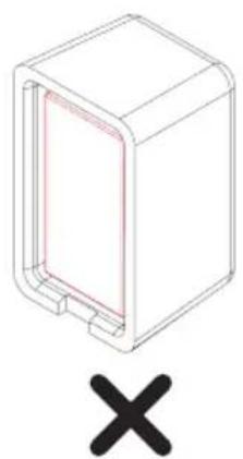
3D diagram of a rectangular enclosure with a red inner panel and a black X symbol below (no text or labels)DE Magneten senkrecht nebeneinander einlegen!
GB Insert magnets vertically next to one another!
FR Insérer les aimants verticalement côte à côte!
NL Magneten verticaal naast elkaar aanbrengen!
⑪ Inserire i magneti l'uno accanto all'altro in verticale!
ES ¡Insertar los imanes verticalmente uno al lado de otro!
8.1b

natural_image
Isometric line drawing of a rectangular device with internal heat exchanger (no text or symbols)①

natural_image
Isometric line drawing of a rectangular device with internal compartments and a central circular element (no text or symbols)
natural_image
Technical line drawing of a mechanical housing component (no text or symbols)K

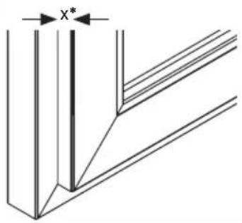
$$ x = 0 - 7 \mathrm{mm} $$
$$ x = 8 - 1 2 \mathrm{mm} $$
$$ x = 1 3 - 1 6 \mathrm{mm} $$
$$ x = 1 7 - 3 0 \mathrm{mm} $$
$$
$$
$$ 7 \mathrm{mm} $$
$$ 1 4 \mathrm{mm} $$
$$ 7 + 1 4 \mathrm{mm} $$


DE *x = Falzhöhe
GB *x = Rebate height
FR *x = Recouvrement
NL *x = 0pdekmaat
IT *x = Altezza d'incassatura
ES *x = Altura de encaje
8.1c
FCA3000

natural_image
Technical line drawing of a mechanical device with no visible text or symbolsFSA3550

natural_image
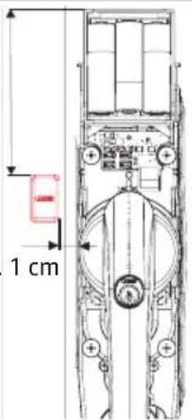
Technical line drawing of a mechanical assembly with no visible text or symbolsca.
9 cm
max. 1 cm
DE
Position magnet holder and bases (Attention: do not fasten yet!)
FR
Press in cylinder. After 2 seconds, the arming tone sounds. Mark the position of the holder.
FR
If the signal does not sound, the position was not detected. Check the position of the holder and the number of supports, or rotate the magnets by 180°!
DE Unterlage(n) und Magnethalterbefestigung an der markierten Stelle mit Schraube S12 / S13 anschrauben. Magnethalter H aufdrücken.
GB Screw base(s) and magnet holder fixing at the marked position with screw S12 / S13. Press down on the magnet holder H.
FR Visser les cale(s) et la fixation du support de l'aimant à l'endroit marqué par vis S12 / S13. Apposer le support de l'aimant H.
NL Schroef basis(sen) en de bevestiging magneethouder op de gemarkeerde plek met schroef S12 / S13. Druk de magneethouder H erop.
⑪ Montare le basi e il fissaggio supporto magnetico al punto segnato con la vite S12 / S13. Premere il supporto magnetico H.
ES Atornillar el/los lecho/s y la fijación del soporte magnético en el punto marcado con los tornillos S12 / S13. Presionar el soporte magnético H.
i
DE Optional kann ein Glasbruchmelder ABUS GBM7300 B (braun) / W (weiß) per Draht an die Schraubklemme der Elektronikeinheit angeschlossen werden. Dazu Drahtbrücke losschrauben, entfernen und durch die beiden Kabelenden des GBM ersetzen. FCA3000 / FSA3550 löst dann auch bei Detektion von Glasbruch Alarm aus. Zur Kabeldurchführung öffnen Sie das Gehäuse an der seitlich vorperforierten Stelle.
GB An ABUS GBM7300 B (brown) / W (white) passive glass break detector can be optionally attached by wire to the screw terminals of the electronic unit. For this, unscrew the wire bridge, remove and replace it with both ends of the GBM cable. Then the FCA3000 / FSA3550 alarm is also triggered by detecting glass breakage. For cable entry, open the housing on the already perforated side.
FR Il est possible de raccorder un détecteur de bris de vitre ABUS GBM7300 B (brun) / W (blanc) par le biais d'un fil métallique sur la borne à vis de l'unité électronique. Ensuite déclipser et remplacer par les deux extrémités du câble de GBM. L'alarme FCA3000 / FSA3550 se déclenche aussi en détectant des bris de vitre. Pour le passage de câbles, ouvrez le boîtier sur le côté déjà perforé.
NL Optioneel kan er ook een glas-breukmelder ABUS GBM 7300 B (bruin) / W (wit) per kabel op de schroefklem van het elektronische systeem worden aangesloten. Daarvoor de draadbrug verwijderen en door de beide kabeleinden van de GBM vervangen. De FCA3000 / FSA3550 alarmeert dan ook bij glasbreuk. Voor de doorvoer van de kabel opent u het huis op de aan de zijkant voorgevormde plaats.
⑪ Come optional, si può collegare un rilevatore di rottura vetri ABUS GBM7300 B (marrone) / W (bianco) tramite filo al morsetto a vite della centralina elettronica. Svitare e rimuovere il ponticello, sostituirlo con le due estremità del cavo del GBM. FCA3000 / FSA3550 fa quindi scattare l'allarme anche in caso di rilevamento di rottura vetro. Per eseguire il passaggio cavi, aprire la cassetta nei punti pre-perforati posti sul lato.
De forma opcional, un avisador de rotura del cristal ABUS GBM7300 B (marrón) / W (blanco) puede conectarse por cable al borne roscado de la unidad electrónica. Para ello, desatornillar el puente de cable, retirarlo y sustituirlo por los dos extremos de cable del GBM. A continuación, el FCA3000 / FSA3550 activa la alarma al detectar una rotura del cristal. Para pasar el cable, abra la carcasa por el lateral perforado.


natural_image
Technical line drawing of a mechanical assembly with no visible text or symbols

natural_image
Technical line drawing of a mechanical assembly with no visible text or symbols
natural_image
Technical line drawing of a mechanical device with attached cable and connector (no text or symbols)8.2 FCA3000
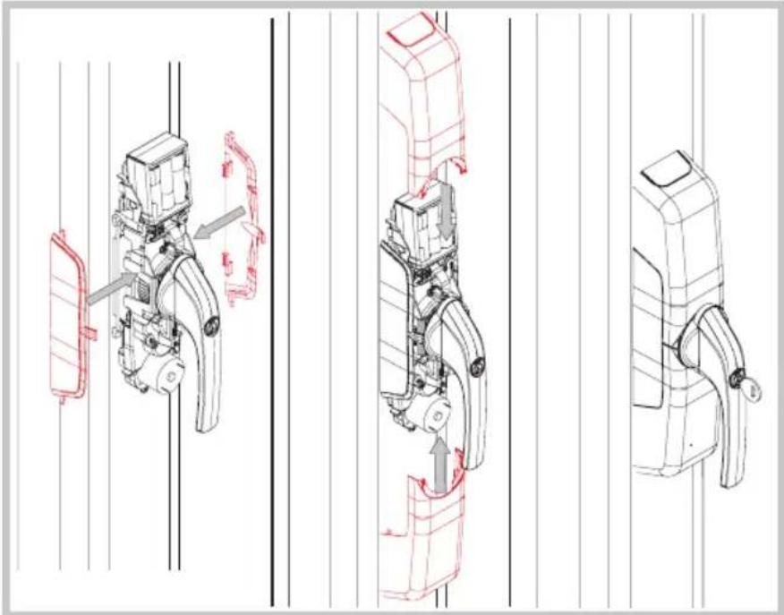
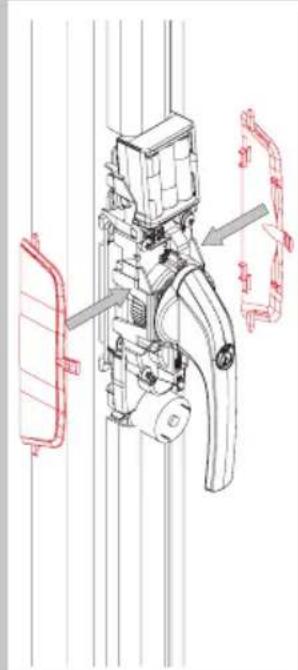
DE Anbringen der
Abdeckkappen
GB Attaching the covering plates)
FR Mise en place des couvercles
NL Afdekkappen aanbrengen
IT Montaggio della copertura
ES Montaje de las tapas de cubierta
natural_image
Technical line drawings of mechanical components with red annotations indicating movement or assembly (no text or symbols present)8.2 FSA3550
DE Anbringen der Abdeckkappen
GB Attaching the covering plates)
FR Mise en place des couvercles
NL Afdekkappen aanbrengen
IT Montaggio della copertura
ES Montaje de las tapas de cubierta
natural_image
Technical line drawing of a mechanical device with red annotations indicating components (no readable text or symbols)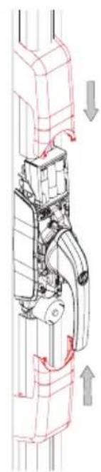
natural_image
Technical diagram of a mechanical assembly with directional arrows indicating movement (no text or labels)
natural_image
Technical line drawing of a mechanical latch or lever mechanism (no text or symbols)9.
DE Batteriewechsel/Pflege
G8 Battery replacement/Maintenance
FR Echange des piles/Entretien
NL Batterijen vervangen/Onderhoud
⑪ Sostituzione delle batterie/Mantenimento
E3 Cambio de pilas/Cuidado

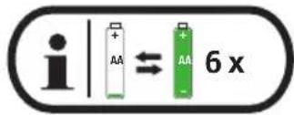
If the battery charge is too low, five short beeps are sounded before the movement begins or when the cylinder is pushed in. It is still possible to set the alarm for a short time, however. Please replace the flat batteries promptly when the signal tone sounds: slide the top cover upwards. Remove the batteries and insert new alkaline batteries. "Ready-to-use" batteries are also suitable, e.g. "Eneloop type BK-3MCCE". Follow the battery instructions and always replace all batteries! 4.4, page 13.
Note: do not confuse the five short beeps with the five sustained beeps that are reporting an attempt at burglary, and those that take place after the drive has started to move!
- The drive cannot be programmed, there is no acknowledgement tone ==> drive plate on back of housing is not set correctly (go to 4.2f)
- It is not possible to move to zero position (handle in closed position) ==> Adjust ease of operation of the door, fixing screws may be too tight loosen slightly, optimise mechanical fitting
- The wireless remote control or wireless keypad in combination with another HomeTec Pro door or window drive are not working properly ==> Program the 1st drive with a single click and the 2nd drive with a double click on the wireless remote control (see CFF3000 wireless remote control manual) ==> Program the drives separately on the keypad (drive 1, drive 2, drive 3) (see CFT3000 wireless keypad manual)
- When opening the window / patio door from its tilt position, and it falls out of its anchoring ==> Deactivate tilt function or support door during motorised movement (go to 7, menu level 2, Setting tilt function)
- During the motorised movement, a warning signal sounds, the drive jams and the window handle also stops in an undefined position (overload of the drive) ==> Check ease of movement of the window / patio door and adjust as necessary ==> Increase drive torque if necessary (go to 7, menu level 2, Setting torque)
- A short beep sounds five times before motorised movement or when pressing in the pressure cylinder ==> "Low batt" message, replace all batteries with new alkaline batteries or fully charged "ready-to-use" batteries (go to 4.4)
- A sustained beep sounds five times after motorised movement or when pressing in the pressure cylinder ==> An attempt at burglary has likely taken place. Please check your window for possible evidences of a forced entry and, if need be, inform the police.
- When the cylinder is pushed in, and there is no acknowledgement tone after 2 seconds ==> The window handle is not in closed position ==> Check the magnet position (go to 8)
- The handle cannot be operated mechanically ==> Cylinder pushed in, unlock with key
- When the pressure cylinder is pushed in in closed position and the acknowledgement tone sounds, it is followed by the alarm tone ==> Glass breakage sensor is defective or incorrectly connected (go to GBM, page 57) ==> Wire bridge accidentally removed without connection of a glass breakage sensor (go to GBM, page 57)
FR FAQ
ABUS products are designed, manufactured and tested in accordance with applicable regulations with great care. The warranty exclusively covers faults that are caused by material or manufacturing defects. If a material or manufacturing defect can be proven, the product will be repaired or replaced at the discretion of the warrantor. In such cases, the warranty ends with the termination of the original warranty period. Any further claims are expressly excluded.
ABUS assumes no liability for defects or damage that has been caused by external influences (e.g. transport, external forces), improper use, normal wear and tear or non-compliance with this operating and installation instructions document. The included batteries are not covered by the warranty. If a warranty claim is asserted, the product must be returned with the original receipt with date of purchase and a brief written description of the fault.
Declaration of Conformity
ABUS August Bremicker Söhne KG, Altenhofer Weg 25, 58300 Wetter hereby declares that the Wireless system type HomeTec Pro is in compliance with the essential requirements and other relevant provisions of Directive 2014/53/EU. The full EU Declaration of Conformity text can be found at: www.abus.com.
Disposal
Dispose of the device in accordance with EU Directive 2002/96/EC – WEEE (Waste Electrical and Electronic Equipment). If you have any questions, please contact the municipal authority responsible for disposal. You can get information on collection points for waste equipment from your local authority, from local waste disposal companies or your dealer.
Subject to technical alterations. No liability for mistakes and printing errors.


The Ground Truth image displays a single, solid horizontal line. According to Rule 2 (UNDERSCORE & LINE RULES), this is a stylistic or background line, not a placeholder underscore. Therefore, the OCR result must ignore it and output nothing or only meaningful text. The provided OCR content is "____", which consists of four underscores. This is an incorrect interpretation of the line as a placeholder, violating the rule that stylistic lines must be ignored. The OCR has hallucinated underscores where none should exist based on the GT's visual context. Hence, the OCR result is inconsistent with the Ground Truth.
© ABUS 2018. ABUS August Bremicker
Söhne KG, DE-58292 Wetter
Tel.: +49 (0) 23 35 63 40
www.abus.com|info@abus.de
CE


- HomeTec Pro™ FCA3000 / FSA3550
- FR
- 4.
- 4.1
- 4.3
- 4.3a
- 4.3b
- d4
- 4.4
- DE
- Batteriehinweise
- Battery instructions
- NL
- D
- 5.2
- n
- 5.4
- a
- 5.4b
- 5.4c
- 5.4d
- 5.4e
- 5.5
- a
- b
- 5.5c
- d
- e
- Level 1 - Programming the drive
- Level 1 - Programming of remote control(s) and keypad
- Level 1 - Clearing remote control(s) and keypad
- Level 1 - Resetting to factory settings (factory reset)
- Level 2 - Advanced menu settings
- 8.1c
- i
- FCA3000
- FSA3550
- 9.
- FR FAQ
- Declaration of Conformity
- Disposal
Brand : ABUS
Model : HomeTec Pro FCA3000
Category : Alarm system