
FUMO50030 - Alarm system ABUS - Free user manual and instructions
Find the device manual for free FUMO50030 ABUS in PDF.
| Product type | Wireless information module |
| Brand | ABUS |
| Model | FUMO50030 |
| Category | Alarm system |
| Dimensions (L x H x D) | 123,9 x 123,9 x 40,7 mm |
| Weight | 200 g |
| Power supply | 9-14 V DC, nominal 12 V DC |
| Standby power consumption | 55 ±5 % mA |
| Alarm power consumption | 600 mA |
| Radio frequency | 868,6625 MHz |
| Transmission power | max. 10 mW |
| Protection rating | IP54 |
| Operating temperature | -10 °C to +55 °C |
| Max. relative humidity | 96 % |
| Display | 8 multi-colored LEDs (green, red, yellow) |
| Internal siren | Piezo, approx. 90 dB(A) at 1 m |
| Radio range | up to 100 m (depending on environment) |
| Security level | 2 (EN50131-1 and -3) |
| Package contents | Module, 3 wall plugs, 3 screws, multilingual manual |
| Installation | Indoor wall mounting, 12 V DC power supply required |
| Main functions | Sector status display, alarm siren, acoustic signals |
Frequently Asked Questions - FUMO50030 ABUS
User questions about FUMO50030 ABUS
0 question about this device. Answer the ones you know or ask your own.
Ask a new question about this device
Download the instructions for your Alarm system in PDF format for free! Find your manual FUMO50030 - ABUS and take your electronic device back in hand. On this page are published all the documents necessary for the use of your device. FUMO50030 by ABUS.
USER MANUAL FUMO50030 ABUS
natural_image
White square electronic device with a small display showing '10000' and '10000' on its surface (no readable text or symbols beyond basic markings)FUMO50030
BOM-No. 12892818
CE
Funk-Infomodul
Installation instructions (UK)......25
natural_image
White square electronic device with a small display showing '10000' and '10000' on its surface (no readable text or symbols beyond basic markings)FUMO50030
CE
0. Preface
Dear customers,
Many thanks for your purchase of this wireless info module for your Secvest wireless alarm centre. This product is built according to state-of-the-art technology. To maintain this status and to guarantee safe operation, it is your obligation to observe these instructions. In the event of questions, please contact your local specialist dealer. No part of the product may be changed or modified in any way. This manual contains important installation and operation instructions. Store these instructions in a safe place for future reference. These instructions are an important product accessory. Bear this in mind if you pass the product on to others. Everything possible has been done to ensure that the contents of these instructions are correct. However, neither the author nor ABUS Security-Center GmbH & Co. KG can be held liable for loss or damages caused directly or indirectly by these instructions, whether real or alleged. We reserve the right to make changes to these instructions without prior notice.
© ABUS Security-Center GmbH & Co. KG, 07/2017
1. Usage in accordance with regulations
This wireless info module displays the status of the selected partition. It is used for the acoustic reproduction of information and alarm tones on your wireless alarm centre.
The installed piezo signaller is also used as an internal siren during an alarm.
It is placed mainly on side doors or garage doors as well as all other possible access areas.
The equipment contacts and connected components must be kept free of moisture (bathrooms and similar surroundings must be strictly avoided).
Use of this product for other than the described purpose may lead to damage of the product. The product operates with a 12 V DC/≥600 mA mains supply or flush-fitting power supply unit.
No part of the product may be changed or modified in any way.
2. Contents
- Preface.... 19
- Usage in accordance with regulations....20
- Contents....21
- Safety information....22
- Scope of delivery 22
- Displays and the operating element 22
- Acoustic signal tones 24
- Installation....25
7.1. Location check 26
7.2. Opening the housing 26
7.3. Attaching the rear housing wall 28
7.4. Allocating the Secvest to the info module 28
7.5. Finishing the installation.... 30
- Testing the signal strength....30
8.1. Carrying out a signal strength test.... 30 - Technical data .... 31
- Information on device disposal 32
- Declaration of Conformity 32
3. Safety information
Caution!

Improper or careless installation work may lead to misinterpretation of signals. This could result in false alarms. The costs resulting from the deployment of emergency services (e.g. fire or police) are borne by the operator of the equipment.
The device is designed for indoor use only.
Pay attention to the notes and instructions in these operating instructions! If you do not follow these instructions, your guarantee claim becomes invalid! Use of this product for other than the described purpose may lead to damage to the product. The electronic part of the product must not be changed or modified in any way. No liability can be accepted for resulting damages!
4. Scope of delivery
Wireless info module
3 x wall plugs (8 x 36 mm)
3 x screws (3 x 33 mm)
Multilingual instructions
5. Displays and the operating element
The info module has eight LEDs arranged one below the other.
These display the following information:

LED power supply (green)
Lights up constantly when the power supply is present.

LED reception (green)
Flashes each time the info module receives a valid reception signal.

LED activated (red)
Lights up when the set partition is activated.

LED warning (yellow)
Lights up when a reset of the wireless alarm centre is necessary or the alarm centre has information ready to display.

LED internal activated (yellow)
Lights up when the set partition is activated internally.

LED ready (red)
Lights up when at least one zone on the set partition is opened or the centre is in installer mode.
(The menu point “INSTALLER MENU → Other Devices → Info Module/Int Siren → Rdy-to-Set LED” on the wireless alarm centre must be set to “Activated”.)

LED delay time (yellow)
Lights up when the input or output delay runs.

LED alarm (red)
Lights up when an alarm is triggered. The piezo signaller also emits a sound.
A small hole at the bottom-right of the housing provides access to an internal switch that is used for monitoring the signal strength.
6. Acoustic signal tones
The info module can generate a whole series of acoustic signal tones. These are similar to the signal tones of the wireless alarm centre. At the same time, the internal piezo signaller of
the wireless info module is activated during an alarm and thus serves as an additional internal siren.
The following table gives an overview of the signal tones and their meaning.
| Signal tone | Meaning |
| Short beep (beep) | The system is faulty and the centre cannot be activated. |
| Interrupted beeps (beep...beep...beep) | A zone was opened during the output delay time. This must be closed before the delay time expires. |
| Long, continuous beep (beeeeeeeeeeeeep) | The output delay time is active. All zones are closed, the centre is activated after the delay time expires. |
| Short, interrupted beeps (beepbeepbeepbeep) | The input delay time is active. |
| Beeps at different pitch | The centre was successfully activated.Teach signal received and stored.When the installer menu is exited.Door chime (when selected under zone attributes). |
7. Installation
The module should be attached to the wall at a practical height for the operator. Ensure that a suitable 12 V power supply is available. The info module can be installed up to 100 metres
from your wireless alarm centre. The reception range is strongly dependent on the structural characteristics of the building.
7.1. Location check
The incoming signal strength should be measured at the planned installation location for the info module. The FU3801 wireless testing box from our product range can be used for this purpose. If you do not possess a wireless testing box, then the info module itself can be used to display the signal strength (see “Testing the signal strength”).
Avoid installation in the following locations:
Next to or on large metal structures. Less than one meter away from power lines and metal, water and gas pipes. Inside steel cases. Next to electrical devices, especially computers, photocopiers or communication devices.
7.2. Opening the housing
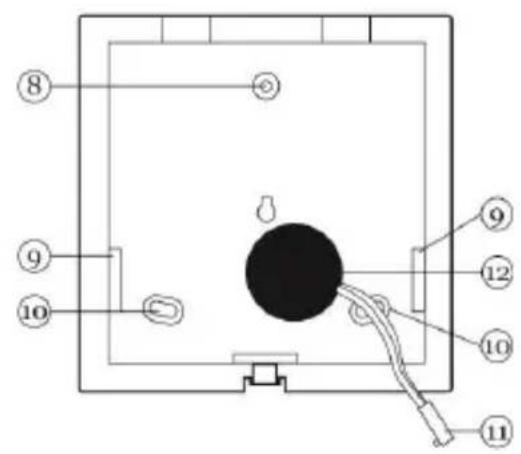
To access the rear wall, loosen the screw at the bottom of the housing (1) and move the front part upwards carefully (2). Disconnect the piezo signaller cable from the PCB (3) before completely removing the rear wall.

Fig. 1: Opening the housing
- Jumper connection for selecting the partition
- Key for displaying the signal strength
- Screw terminal block for 12 V connection
- Potentiometer
- Connector for internal piezo signaller
- Wireless reception module
- LEDs
- Upper fixing hole
- Cable feed openings
- Fastening holes
- Connection cable for piezo signaller
- Piezo signaller
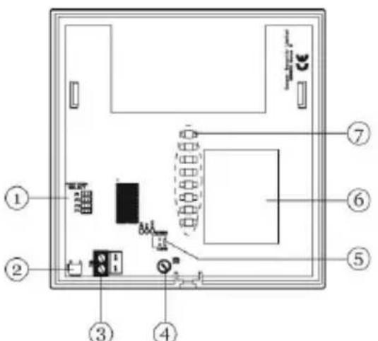
Fig. 2: Interior view

7.3. Attaching the rear housing wall
-
Using the base plate as a drilling template, mark the drill holes on the wall. Drill the holes and insert wall plugs if necessary.
-
Feed the connection cable of the PSU into the device and screw the rear housing side onto the wall.
7.4. Allocating the Secvest to the info module
-
Firstly ensure that no jumper is inserted on the info module. Attach the power supply to the info module (the polarity of the terminal block is printed on the PCB). The lower seven LEDs flash. Learning mode is now active.
-
In the installer menu of the wireless alarm centre, select the “Other Devices → Info Module/Int Siren → Teach Device” menu point.
-
Press "Send" on the wireless alarm centre. The centre sends the teach signal to the info module. After successful teaching of the wireless alarm centre:
-
The seven lower LEDs on the info module stop flashing.
- All LEDs light up constantly.
-
The info module emits a double tone.
-
Confirm the successful teaching procedure on the wireless alarm centre.
- Define which partition should be used by the info module. Select the partition using the jumper.
When a partition has been selected, the info module emits a double tone again. Only the green power supply LED is still lit.
The info module has left the learning mode.
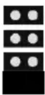
The diagram shows the jumper setting for the different partitions:
Partition 1

Partition 2
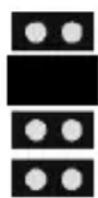
Partition 3
Partition 4
7.5. Finishing the installation
If no wireless location check has been made, then it is important that the strength of the incoming signal is checked now (see “Testing the signal strength”).
When the signal strength is satisfactory:
- Reattach the piezo signaller cable to the PCB.
- Attach the front part of the housing to the rear wall and fasten it with the screw (carry out the steps in figure 1 in reverse order).
8. Testing the signal strength
The info module can display the signal strength of signals received from the alarm centre.
Important:

Make sure that the alarm centre is taught to the info module.
Ensure that a jumper is inserted for selecting the partition.
8.1. Carrying out a signal strength test
As soon as the info module has received a signal from the wireless alarm centre, press the button for displaying the signal strength on the info module (use a long, sharp tool that fits through the hole on the bottom of the housing).
The LEDs display the strength of the received signal. The more LEDs are lit (from bottom to top), the stronger the signal. If two LEDs or less are lit, then the signal is not strong enough for reliable operation. The green power supply LED is always lit.
9. Technical data
| Environment class | II |
| Security level | 2 EN50131-1 und -3 |
| Protection class | IP 54 |
| Operating temperature | -10 °C to +55 °C |
| Humidity | 96% relative humidity |
| Dimensions | 123.9 x 123.9 x 40.7 mm(W x H x D) |
| Weight | 200 g |
| Power supply | 9-14 V DC, 12 V DC nominal |
| Power consumption | 55 ±5% mA (standby)600 mA (alarm) |
| Frequency | 868.6625 MHz |
| Display | 8 LEDs of different colours |
| Signals | Internal piezo signaller(ca. 90 dB (A) @ 1 m) |
| Tamper monitoring | No |
| Wireless transmission power | Max. 10mW |
Subject to alterations and errors.
10. Information on device disposal
The EU Directive 2012/19/EU regulates the proper return, treatment and recycling of used electronic devices. This symbol means that in the interest of environmental protection the device must be disposed of separately from household or industrial waste at the end of its service life in accordance with applicable local legal guidelines. Disposing of used devices can be done at official re-cycling centers in your country. Obey local regulations when disposing of material. Further details on returns (also for non-European countries) can be obtained at your local authority. Separate collection and recycling saves natural resources and ensures that all the provisions for protecting health and environment are observed when recycling the product.
11. Declaration of Conformity
Hereby, ABUS Security-Center GmbH & Co. KG declares that the radio equipment type FUMO50030 is in compliance with Directive 2014/53/EU. The full text of the EU declaration of conformity is available at the following internet address: www.abus.com >> Search >> FUMO50030 >> Downloads
The Declaration of Conformity can also be obtained from the following address:
natural_image
White rectangular electronic device with a vertical indicator on the left side (no visible text or symbols)FUMO50030
CE
0. Préface
Chère cliente, cher client,

natural_image
White square electronic device with a small display screen showing text (no readable symbols or labels)FUMO50030
CE
0. Prefazione
Egregio cliente,

Fig. 2: vista interna
natural_image
White square electronic device with a small display screen showing text (no readable symbols or labels)FUMO50030
CE
0. Voorwoord
Geachte klant,
natural_image
White square electronic device with a small display showing '10000' and '10000' on its surface (no readable text or symbols beyond basic markings)FUMO50030
CE
0. Forord
Kære kunde.


- Funk-Infomodul
- Preface
- Usage in accordance with regulations
- Contents
- Safety information
- Caution!
- Scope of delivery
- Displays and the operating element
- LED power supply (green)
- LED reception (green)
- LED activated (red)
- LED warning (yellow)
- LED internal activated (yellow)
- LED ready (red)
- LED delay time (yellow)
- LED alarm (red)
- Acoustic signal tones
- Installation
- Location check
- Avoid installation in the following locations:
- Opening the housing
- Attaching the rear housing wall
- Allocating the Secvest to the info module
- Finishing the installation
- Testing the signal strength
- Important:
- Carrying out a signal strength test
- Technical data
- Information on device disposal
- Declaration of Conformity
- Préface
- Prefazione
- Voorwoord
- Forord
Brand : ABUS
Model : FUMO50030
Category : Alarm system