SUB 918 - Subwoofer DB Technologies - Free user manual and instructions
Find the device manual for free SUB 918 DB Technologies in PDF.
| Product type | Active subwoofer |
| Brand | DB Technologies |
| Model | SUB 918 |
| Dimensions (W x H x D) | 720 x 530 x 690 mm |
| Weight | 41.8 kg |
| Power supply | PowerCON TRUE1, 220-240V~ / 110-120V~ (auto-select) |
| Amplifier | DIGIPRO G3, 900 W RMS, Class D |
| Frequency response | 42 Hz - cutoff frequency (variable 70-110 Hz) |
| Max SPL (1 m) | 134 dB |
| Speaker | 18" (4" voice coil) |
| DSP controls | Polarity (Normal/Reverse), Delay (ms), Xover/Link (cutoff frequency), Input sensitivity |
| Input/output connectors | Balanced XLR (input and output), RDNet (etherCON/RJ45), USB Data Service |
| Cabinet material | Plywood with black protective paint |
| Protective grille | CNC machined (do not remove) |
| Handles | 2 side handles (do not use for suspension) |
| Pole mount | Yes, 36 mm diameter (M20 thread), accessories DS2-S or DS-2 |
| Power consumption | Idle: 21 W; 1/8 power: 1.2 A (220-240V~); 1/3 power: 2.7 A (220-240V~) |
| Fuse | Yes, mains fuse holder |
| Maintenance and cleaning | Clean with a dry cloth. Do not open the amplifier. Disconnect before any maintenance. |
| Safety | Never remove the grille. In case of overheating, volume is reduced automatically. Cut the power in case of malfunction. |
| Spare parts and repairability | Contact an authorized repairer. Do not attempt repair yourself. |
| General information | Register the product at dbtechnologies.com (SUPPORT section). Warranty included. |
Frequently Asked Questions - SUB 918 DB Technologies
User questions about SUB 918 DB Technologies
0 question about this device. Answer the ones you know or ask your own.
Ask a new question about this device
Download the instructions for your Subwoofer in PDF format for free! Find your manual SUB 918 - DB Technologies and take your electronic device back in hand. On this page are published all the documents necessary for the use of your device. SUB 918 by DB Technologies.
USER MANUAL SUB 918 DB Technologies
natural_image
Technical line drawing of a rectangular electronic enclosure with mounting holes and internal compartments (no text or symbols)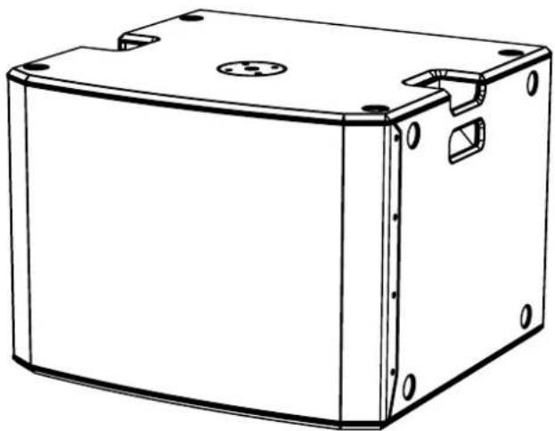
natural_image
Technical line drawing of a rectangular electronic enclosure with mounting holes and internal components (no text or symbols)USER MANUAL - Section 1
The warnings in this manual must be observed together with the "User Manual - Section 2".
According to the standards EN 55103 this equipment is designed and suitable to operate in E3 (or lower E2, E1) Electromagnetic environments.
FCC CLASS B STATEMENT ACCORDING TO TITLE 47, CHAPTER I, SUBCHAPTER A, PART 15, SUBPART B
This equipment has been tested and found to comply with the limits for a Class B digital device, pursuant to part 15 of the FCC Rules. These limits are designed to provide reasonable protection against harmful interference in a residential installation. This equipment generates, uses and can radiate radio frequency energy and, if not installed and used in accordance with the instructions, may cause harmful interference to radio communications. However, there is no guarantee that interference will not occur in a particular installation. If this equipment does cause harmful interference to radio or television reception, which can be determined by turning the equipment off and on, the user is encouraged to try to correct the interference by one or more of the following measures:
—Reorient or relocate the receiving antenna.
—Increase the separation between the equipment and receiver.
—Connect the equipment into an outlet on a circuit different from that to which the receiver is connected.
—Consult the dealer or an experienced radio/TV technician for help.
Changes or modifications not expressly approved by the party responsible for compliance could void the user's authority to operate the equipment.
WARNING
Make sure that the loudspeaker is securely installed in a stable position to avoid any injuries or damages to persons or properties. For safety reasons di not place one loudspeaker on top of another without proper fastening systems. Before hanging the loudspeaker check all the components for damages, deformations, missing or damaged parts that may compromise safety during installation. If you use the loudspeakers outdoor avoid spots exposed to bad weather conditions.
Contact dBTechnologies for accessories to be used with the speakers. dBTechnologies will not accept any responsibility for damages caused by inappropriate accessories or additional devices.
SUB 915 - SUB918 Cod. 420120322 REV. 1.0
ITALIANO
ENGLISH
DEUTSCH
FRANÇAIS
ESPAÑOL
INDICE
2. PRIMA ACCENSIONE.... 10
COLLEGAMENTO DEGLI INGRESSI E RILANCIO AUDIO.... 11
INGRESSI E USCITE 16
natural_image
Technical drawing of a mechanical component with mounting holes and a central circular feature (no text or symbols)
natural_image
Technical drawing of a mechanical component with mounting holes and a central circular feature (no text or symbols)
natural_image
Pure technical drawing of a rectangular frame with dimension标注 (no text or symbols)
natural_image
Simple line drawing of a rectangular frame with dimension label 720 (no text or symbols beyond the measurement)SUB 915 - SUB918 Cod. 420120322 REV. 1.0
natural_image
Diagram of a device rear panel with internal circuitry and directional arrows indicating flow or movement (no text or symbols)
text_image
MAINS LINKAUTO-RANGE MAINS INPUT 230-360V~50-60Hz 2.7A 100-120V~50-6Hz 4.7A 238-360V~[43.3Amax] 390WMax 100-120V~[45.3Amax] 180WMax MAINS FUSE SUB QAS SUB QAS SUB INDUSTRIES S.E.L. Sub Industries & Localized Casplics 2022 VALEKINDIA (HCL - RAY) EWC CESUB915 - SUB918 Cod. 420120322 REV. 1.0
4. Xover/Link rotary
6. LED (Limiter, Signal/ON)
text_image
CAUTION RISK OF ELECTRONIC SUPPORT NOT OPEN "ATTENTION" SUPPORT DE "CHASE" ELECTRONIC NET SUFFER MAINS INPUT 220-240V~ 50-60Hz 2,7A 100-120V~ 50-60Hz 4,7A MAINS LINKAUTO-RANGE 220-240V~ (13,3Amax) 3050Wmax 100-120V~ (15,3Amax) 1680Wmax MAINS FUSE 220-240V~ (T4A L 250V~ 100-120V~ (T8A L 250V~) RESISTANCE WITH RESISTANCE RESISTANCE WITH RESISTANCE RESISTANCE WITH RESISTANCE SUB 915 SUB 918 The short coils with part 13 of the RC blocks. Occurrence to optes to the leading two conditions. The device may not cause horizontal protection, and the device must change any performance reduced, including interference, the may continue operation. AEB INDUSTRIALE S.R.L. Via Broodulin, B Localito Crescillano 40063 VAL SAMIDOGIA (BO) - ITALY EMC CE7. Subwoofer Delay
- Subwoofer Polarity:
natural_image
Technical line drawing of a mechanical device with two stacked components (no text or symbols)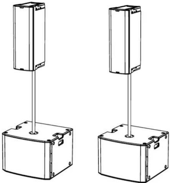
natural_image
Two identical mechanical or electrical enclosure units with vertical posts and mounting base (no text or symbols visible)SUB915 - SUB918 Cod. 420120322 REV. 1.0
4. RISOLUZIONE DEI PROBLEMI
| Controlli: | Delay, Xover/Link, Polarity, Sensitivity |
INGRESSI E USCITE
| Ingressi: | 2 x XLR Balanced Inputs |
| Uscite: | 2x XLR Balanced Outputs |
PRODUCT OVERVIEW.... 19
USER REFERENCE 19
MECHANICAL AND ACOUSTICAL FEATURES 20
DIMENSIONS 20
FEATURES OF THE AMPLIFIER AND CONTROL SECTIONS.... 21
INPUT, OUTPUT AND CONTROL SECTION 22
POWER SUPPLY UNIT SECTION 23
2. FIRST POWER-UP 24
INPUT CONNECTIONS AND AUDIO DAISY CHAIN 25
3. USAGE EXAMPLES...... 27
FLOOR USAGE 27
USAGE WITH SPEAKER IN A STACK 27
USAGE ON SUBWOOFER WITH TELESCOPIC POLE 27
4. TROUBLESHOOTING 28
5. SPECIFICATIONS 29
GENERAL INFORMATION 29
ACOUSTICAL SPECIFICATIONS.... 29
AMPLIFIER 29
PROCESSOR.... 30
USER INTERFACE 30
INPUTS & OUTPUTS.... 30
POWER SUPPLY SPECIFICATIONS (ABSORPTION / INSTALLATION) 30
DIMENSIONS 31
SUB 915 - SUB918 Code 420120322 REV. 1.0
1. GENERAL INFORMATION
WELCOME!
Thanks for purchasing a product designed and developed in Italy by dBTechnologies! This ergonomic and versatile active subwoofer is the result of a long experience in the sound reinforcement industry, making use of optimized sound, electronic and material research solutions.
PRODUCT OVERVIEW
The new SUB 900 subwoofers are equipped with a 15" woofer (SUB 915) and an 18" woofer (SUB 918), respectively. Accurate design and sound optimisation allow for high-quality performance in a compact product. Cabinets high ergonomics and ease of handling make them easy to transport. SUB 915 and SUB 918 main features are:
- an ergonomic, compact and versatile project, for both indoors and outdoors
• reliable, silent digital amplifier
• dedicated DSP controls, with Polarity, Delay, Xover, Sensitivity selection
- wooden cabinets for acoustic performance optimisation, with resistant external surfaces for both indoor and outdoor use
USER REFERENCE
To make the most of your subwoofer, we recommend that you:
- read the quick start user manual included in the package and this user manual thoroughly and keep this manual during the whole life of the product.
- Register your product at http://www.dbtechnologies.com under "SUPPORT".
- keep proof of purchase and WARRANTY (User manual "section 2").
SUB915 - SUB918 Code 420120322 REV. 1.0
MECHANICAL AND ACOUSTICAL FEATURES
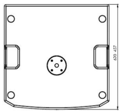
DIMENSIONS
SUB 915 and S918 have the following sizes:
• SUB 915: 620 x 457 x 620 (mm)
• SUB 918: 720 x 530 x 690 (mm)
natural_image
Technical drawing of a mechanical component with mounting holes and a central circular feature (no text or symbols)
natural_image
Technical drawing of a mechanical component with mounting holes and a central circular feature (no text or symbols)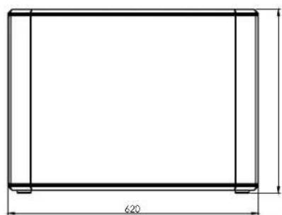
natural_image
Pure technical drawing of a rectangular frame with dimension标注 (no text or symbols)
natural_image
Simple line drawing of a rectangular frame with dimension label 720 (no text or symbols beyond the measurement)SUB 915 - SUB918 Code 420120322 REV. 1.0
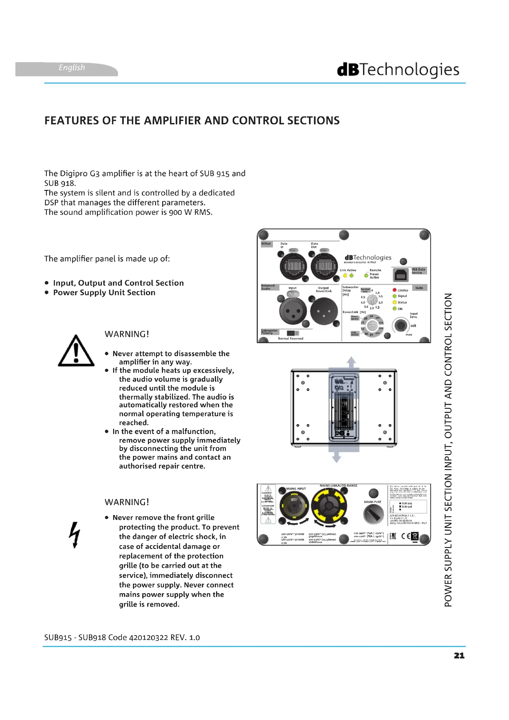
FEATURES OF THE AMPLIFIER AND CONTROL SECTIONS
The Digipro G3 amplifier is at the heart of SUB 915 and SUB 918.
The system is silent and is controlled by a dedicated DSP that manages the different parameters.
The sound amplification power is 900 W RMS.
The amplifier panel is made up of:
• Input, Output and Control Section
• Power Supply Unit Section

WARNING!
- Never attempt to disassemble the amplifier in any way.
- If the module heats up excessively, the audio volume is gradually reduced until the module is thermally stabilized. The audio is automatically restored when the normal operating temperature is reached.
- In the event of a malfunction, remove power supply immediately by disconnecting the unit from the power mains and contact an authorised repair centre.
text_image
RDNet Data In Data Out 2018 2019 dBTechologies SINEMA DEVELOPED IN I/ILAY Link Active Remote Preset Active USB Data Service Balanced Audio Input Output PU 3.1 Xover/Link Subwoofer Polarity Normal Reversed Subwoofer Delay [ms] Sensor 0 1.8 4.5 1.5 4.0 2.0 3.5 3.0 2.5 Main Limiter Signal Status ON Xover/Link [Hz] Power MODE 90 100 70 110 70 120 Line MODE 80 90 100 Input Sons. 0dB MAX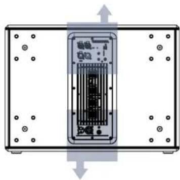
natural_image
Diagram of a device internal structure with arrows indicating direction (no text or symbols)WARNING!
- Never remove the front grille protecting the product. To prevent the danger of electric shock, in case of accidental damage or replacement of the protection grille (to be carried out at the service), immediately disconnect the power supply. Never connect mains power supply when the grille is removed.

text_image
MAINS LINKAUTO-RANGE MAINS INPUT 230-360V~50-60Hz 2.7A 200-120V~50-60Hz 4.7A 238-360V~[43.3Amax] 390WMax 100-120V~[35.3Amax] 180WMax MAINS FUSE SUB OUT SUB OUT SUB INDUSTRIALS S.E.L. Sub Industrials S.E.L. Localized Capacitors 2022 CALIFORNICUM (BCL-TAIY) ENC CE ECE
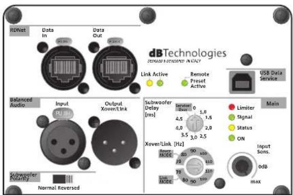
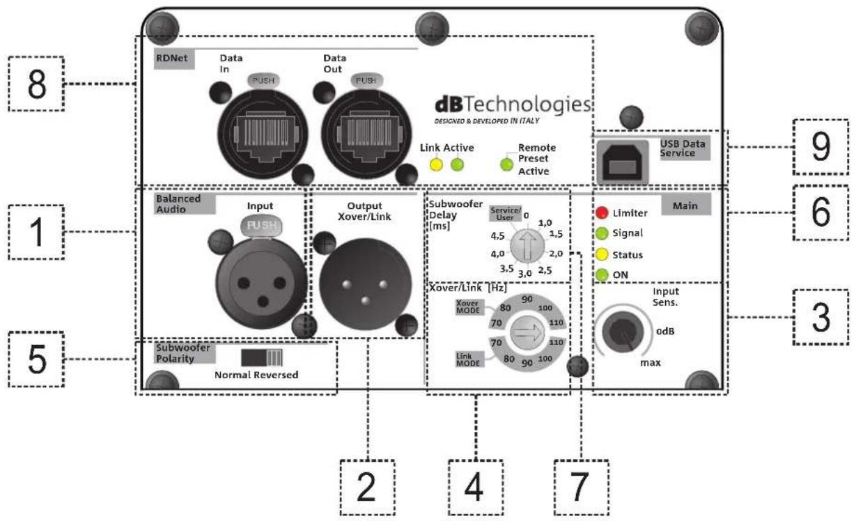
INPUT, OUTPUT AND CONTROL SECTION

text_image
8 RDNet Data In PUSH Data Out PUSH dB Technologies DESIGNED & DEVELOPED IN ITALY Link Active Remote Preset Active USB Data Service 9 1 Balanced Audio Input PUSH Output Xover/Link Subwoofer Delay [ms] 0 1,0 4,5 1,5 4,0 2,0 3,5 3,0 2,5 Main Limiter Signal Status ON Xover/Link [Hz] Xover MODE 80 90 100 70 110 70 110 Link MODE 80 90 100 Input Sens. odB max 2 4 7 3 51. INPUT
XLR (balanced) input connector. For further details concerning connection, refer to INPUT CONNECTIONS AND AUDIO DAISY CHAIN.
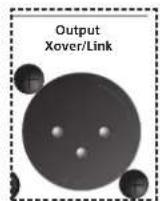
2. OUTPUT
XLR (balanced) output connector. Select the cut-off frequency based on the Xover/Link mode using the relevant rotary control. For further details concerning connection, refer to INPUT CONNECTIONS AND AUDIO DAISY CHAIN.
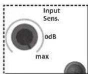
3. Input Sensitivity
Rotary control to adjust the input sensitivity.
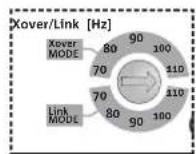
4. Xover/Link rotary
Selector that allows setting the cut-off frequency based on the selected mode (Link/Xover). It acts on the daisy-chained signal from Xover/Link Output connectors.
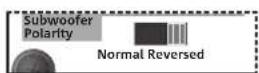
5. Subwoofer Polarity selector
Selector that allows adjusting the Polarity (Normal or Reverse)
6. LED (Limiter, Signal/ON)
Indicator LEDs. The Limiter LED turns on when the internal protection circuit is triggered, while Signal/ON indicates subwoofer power-up as well as the presence of an input audio signal.
SUB 915 - SUB918
Code 420120322 REV. 1.0
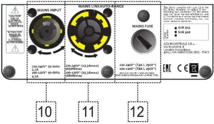
POWER SUPPLY UNIT SECTION
text_image
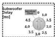
CAUTION RISK OF ELECTRONIC SUPPORT NOT OPEN "ATTENTION" SUPPORT DE "CHASE" ELECTRONIC NET SUFFER MAINS INPUT 220-240V~ 50-60Hz 2,7A 100-120V~ 50-60Hz 4,7A MAINS LINKAUTO-RANGE 220-240V~ (13,3Amax) 3050Wmax 100-120V~ (15,3Amax) 1680Wmax MAINS FUSE 220-240V~ (T4A L 250V~ 100-120V~ (T8A L 250V~) RESISTANCE WITH RESISTANCE RESISTANCE WITH RESISTANCE RESISTANCE WITH RESISTANCE SUB 915 SUB 918 The short coils with part 13 of the RC blocks. Occurrence to optes to the leading two conditions. The device may not cause horizontal protection, and the device must change any performance reduced, including interference, the may continue operation. AEB INDUSTRIALE S.R.L. Via Broodulin, B Localito Crescaggiano 40063 VAL SAMIDOGIA (BO) - ITALY EMC CE7. Subwoofer Delay
Rotary control that allows setting the delay in ms.
8. RDNet section with control LEDs
Section compatible with network cables with etherCON/RJ45 connectors.
In particular, "Data in" must be connected to devices such as RDNet Control 2 or Control 8; "Data Out" is used to link the network to additional modules of the line array in daisy-chain configuration.
The LEDs relating to module network operation (RDNet) ensure real-time monitoring.
In particular, if "Link" is on the RDNet network is active and has acknowledged the device, if "Active" is flashing there is data traffic, if "Remote Preset Active" is on all local control on the amplifier panel are bypassed by the RDNet remote control.
9. Service Data USB
USB connector for firmware update.
10. MAINS INPUT
Compatible with powerCON TRUE1 ^® connector.
11. MAINS LINK
Compatible with powerCON TRUE1 ^® connector for power daisy chain to other modules.
To find the maximum number of modules that can be connected in a re-linked system, see the TECHNICAL SPECIFICATIONS section.
12. MAINS FUSE
Housing for the mains fuse
SUB915 - SUB918
Code 420120322 REV. 1.0
2. FIRST POWER-UP
The package of SUB 915 / SUB 918 subwoofer contains:
• 915 or 918 subwoofer
• POWERCON TRUE1 power cable
- quick start user manual and warranty documents in hard copy
CONFIGURATION AND OPTIMISATION
The subwoofer will turn on after inserting, turning and connecting the powerCON TRUE1 ^® connector to the power supply.
For subwoofer use optimisation in given configurations, the control panel displays the following:
- Xover/Link [Hz]:
- Link (the signal present at OUTPUTS is the one applied to the woofer)
- Xover (the signal present at OUTPUTS is filtered with a crossover frequency of 120 Hz, for daisy chain to a speaker, such as B-HYPE and OPERA)
- Subwoofer Polarity:
- Normal (audio signal normal polarity)
- Reverse (reverse polarity, useful for wavefront optimisation through acoustic wave phase reversal)
- Subwoofer Delay:
It is possible to select the applicable delay for various configurations, according to what is stated on the silk-screen print.
Before power-up, set Input Sensitivity level selector to 0 dB
SUB 915 - SUB918 Code 420120322 REV. 1.0
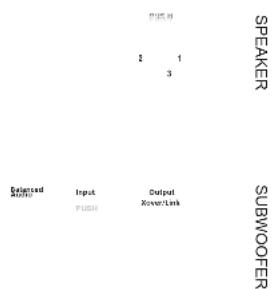
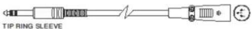
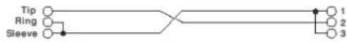
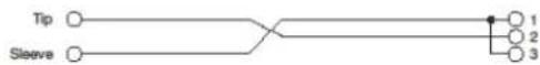
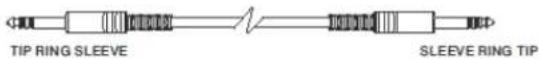
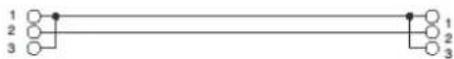
INPUT CONNECTIONS AND AUDIO DAISY CHAIN
Two example figures are shown for illustrative purposes only.
In the event of a connection between subwoofer and speaker:
- Connect mixer output to subwoofer input connector
- Connect subwoofer output connector to speaker input.
- Set subwoofer OUTPUT XOVER/LINK [4] to XOVER, in order to daisy-chain a signal to the speaker having a crossover frequency that can be selected with the Xover/Link rotary control [Hz]


SPEAKER
SUBWOOFER
MIXER
MIXER

text_image
SPEAKER 2 1 3 Balanced Audio Input Qingyi Ri SRI Street&LHR SUBWOOFERMIXER
text_image
作图例 2 1 3 Speaker Balancead MORIANT Input PUSH Output PowerTask SUBWOOFERMIXER
MIXER
• Balanced
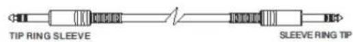
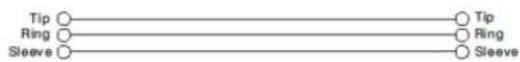

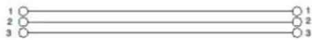
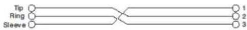
- Unbalanced


3. USAGE EXAMPLES

- Types of installation other than those here described are not allowed.
- Never use the handles to suspend the subwoofer
- Always check that the positioning is stable and that the installation does not pose a danger to people, animals or property.
FLOOR USAGE
915 and 918 subwoofers may be used directly on the floor.
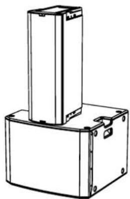
USAGE WITH SPEAKER IN A STACK
A speaker may be installed directly on 915 or 918 subwoofer by means of a DS2-S 35 mm diameter mini-pole (e.g. series: INGENIA, B-HYPE, OPERA).
An additional fastener is required.
natural_image
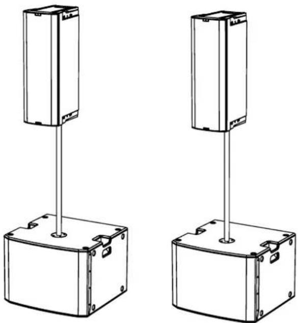
Technical line drawing of a mechanical device with two stacked components (no text or symbols)USAGE ON SUBWOOFER WITH TELESCOPIC POLE
It is possible to use only one speaker mounted on a 35 mm diameter pole. The reference accessory is DS-2 (telescopic pole). An additional fastener is required.
natural_image
Two identical mechanical or electrical enclosure units with vertical posts and mounting holes, shown from different angles (no text or symbols)SUB915 - SUB918 Code 420120322 REV. 1.0
4. TROUBLESHOOTING
The subwoofer will not turn on:
- Check that power supply is present upstream of the installation.
- Ensure that the power supply cable is properly plugged in.
The subwoofer turns on but produces no sound:
- Check that the input connection of the audio signal is correctly performed.
- Check the cables for damage.
- Ensure that the mixer or audio source is on and an output signal is present.
- Check the general level through the "Input Sensitivity" control.
Loudspeaker sound is inappropriate:
- Check the cables for damage and replace them as required (a damaged cable may lead to signal loss or alteration).
- Check that the settings on the control panel are correctly set.
SUB 915 - SUB918 Code 420120322 REV. 1.0
5. SPECIFICATIONS
GENERAL INFORMATION
| Type: | Active subwoofer |
ACOUSTICAL SPECIFICATIONS
| Frequency response [-10dB]: | 45 - Cut freq Hz (SUB 915) / 42 -Cut Freq Hz (SUB 918) |
| Max SPL (1m): | 133 dB (SUB 915) / 134 dB (SUB 918) |
| LF: | 15” (SUB 915) / 18” (SUB 918) |
| LF voice coil: | 4” |
| Crossover frequency: | Variable (70 Hz - 80 Hz - 90 Hz - 100 Hz - 110 Hz) |
AMPLIFIER
| Type: | DIGIPRO G3 |
| Amplification class | Class D |
| Power supply | PowerCON TRUE1 |
| RMS amplifier power: | 900 W |
SUB915 - SUB918 Code 420120322 REV. 1.0
PROCESSOR
| Internal controller: | 28-bit/56-bit DSP |
| Limiter: | Peak, RMS, Thermal |
USER INTERFACE
| Controls: | Delay, Xover/Link, Polarity, Sensitivity |
INPUTS & OUTPUTS
| Inputs: | 2 x XLR Balanced Inputs |
| Outputs: | 2x XLR Balanced Outputs |
POWER SUPPLY SPECIFICATIONS (ABSORPTION / INSTALLATION)
| Absorption at 1/8th of power in medium use conditions (*): | 1.2 A (220-240V~) - 2 A (110-120V~) |
| Absorption at 1/3rd of power in maximum use conditions (**): | 2.7 A (220-240V~) - 4.7 A (110-120V~) |
| Absorption with speaker on in no-signal condition (idle): | 21 W |
| Inrush current: | 21.04 A |
* NOTE FOR INSTALLER: Values refer to 1/8th of power, under average operating conditions (music programme with occasional or no clipping). For any type of configuration we recommend to consider them as minimum sizing values.
** NOTE FOR INSTALLER: Values refer to 1/3rd of power, under heavy operating conditions (music programme with frequent clipping and limiter activation). In case of professional installations and tours we recommend sizing according to these values.
SUB 915 - SUB918 Code 420120322 REV. 1.0
DIMENSIONS
| Material: | Plywood (with protective black paint) |
| Grille: | NC-machined |
| Handles: | 2, on sides |
| Pole mount: | Yes, 36 mm (provision: M20) |
| Width: | 620 mm (SUB 915) 720 mm (SUB 918) |
| Height: | 457 mm (SUB 915) 530 mm (SUB 918) |
| Depth: | 620 mm (SUB 915) 690 mm (SUB 918) |
| Weight: | 34.8 kg (SUB 915) 41.8 kg (SUB 918) |
Product features, specifications and appearance are subject to changes without prior notice. dBTechnologies reserves the right to make changes or improvements in design or manufacture without any obligation to incorporate such changes or improvements in products manufactured before their introduction.

text_image
AEBA.E.B. Industriale Srl
Via Brodolini, 8
natural_image
Technical drawing of a mechanical component with mounting holes and a central circular feature (no text or symbols)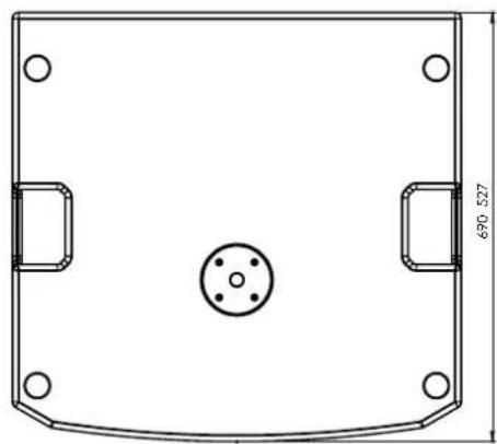
natural_image
Technical drawing of a mechanical component with mounting holes and a central circular feature (no text or symbols)
natural_image
Pure technical drawing of a rectangular frame with dimension标注 (no text or symbols)
natural_image
Simple line drawing of a rectangular frame with dimension label 720 (no text or symbols beyond the measurement)text_image
dBTechologies SERVICES DEVELOPED IN IFLAY Link Active Remote Preset Active USB Data Service Balanced Audio Input Output Xover/Link Subwoofer Delay [ms] Main Subwoofer Delay [ms] Limiter Signal Status ON Xover/Link [Hz] Input Sons. 0dB max Subwoofer Polarity Normal Reversed
natural_image
Diagram of a device internal structure with arrows indicating direction (no text or symbols)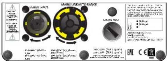
text_image
MAINS LINKAUTO-RANGE MAINS INPUT 230-360V~50-60Hz 2.7A 200-120V~50-60Hz 4.7A 238-360V~[43.3Amax] 390WMax 100-120V~[35.3Amax] 180WMax MAINS FUSE SUB OUT SUB OUT SUB INDUSTRIALS S.E.L. Sub Industrials S.E.L. Localized Capacitors 2022 CALIFORNICUM (BCL-TAIY) ENC CE ECE4. Xover/Link rotary
6. LED (Limiter, Signal/ON)
text_image
CAUTION RISK OF ELECTRONIC SUPPORT NOT OPEN "ATTENTION" SUPPORT DE "CHASE" ELECTRONIC NET SUFFER MAINS INPUT 220-240V~ 50-60Hz 2,7A 100-120V~ 50-60Hz 4,7A MAINS LINKAUTO-RANGE 220-240V~ (13,3Amax) 3050Wmax 100-120V~ (15,3Amax) 1680Wmax MAINS FUSE 220-240V~ (T4A L 250V~ 100-120V~ (T8A L 250V~) RESISTANCE WITH RESISTANCE RESISTANCE WITH RESISTANCE RESISTANCE WITH RESISTANCE SUB 915 SUB 918 The short coils with part 13 of the RC blocks. Occurrence to optes to the leading two conditions. The device may not cause horizontal protection, and the device must change any performance reduced, including interference, the may continue operation. AEB INDUSTRIALE S.R.L. Via Broodulin, B Localito Crescaggiano 40063 VAL SAMIDOGIA (BO) - ITALY EMC CE7. Subwoofer Delay
- Subwoofer Polarity:
natural_image
Technical line drawing of a mechanical device with two stacked components (no text or symbols)VERWENDUNG AUF EINEM SUBWOOFER MIT TELESKOPPFOSTEN
natural_image
Two identical mechanical or electrical enclosure units with vertical posts and mounting holes, shown from different angles (no text or symbols)text_image
Stylized logo or emblem with Chinese characters, possibly a brand or company nameA.E.B. Industriale Srl
Via Brodolini, 8
DONNÉES ACOUSTIQUES 57
AMPLIFICATEUR 57
PROCESSEUR 58
INTERFACE UTILISATEUR 58
ENTRÉES ET SORTIES.... 58
SPÉCIFICATIONS D'ALIMENTATION (ABSORPTION / INSTALLATION) 58
DIMENSIONS 59
SUB 915 - SUB918 Code 420120322 RÉV. 1.0
1. INFORMATIONS GÉNÉRALES
BIENVENUS !
natural_image
Technical drawing of a mechanical component with mounting holes and a central circular feature (no text or symbols)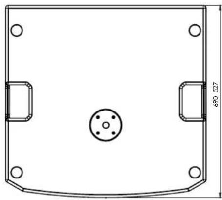
natural_image
Technical drawing of a mechanical component with mounting holes and a central circular feature (no text or symbols)
natural_image
Pure technical drawing of a rectangular frame with dimension标注 (no text or symbols)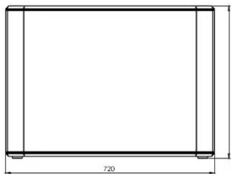
natural_image
Simple line drawing of a rectangular frame with dimension label 720 (no text or symbols beyond the measurement)SUB 915 - SUB918 Code 420120322 RÉV. 1.0
CARACTÉRISTIQUES DE LA SECTION D'AMPLIFICATION ET DE CONTRÔLE
text_image
RDNet Data In Data Out dBTechologies SERIALS & STUDIOING IN VASY Link Active Remote Preset Active USB Data Service Balanced Audio Input Output Xover/Link Subwoofer Reliability Normal Reversed Subwoofer Delay [ms] Servicer Bus 0 1.0 4.5 1.5 2.0 3.5 3.0 2.5 Xover/Link [Hz] Power MODE 80 90 100 70 110 70 110 80 100 Lith MODE Main Limiter Signal Status ON Input Sons. 0dB max
natural_image
Diagram of a device internal structure with arrows indicating direction (no text or symbols)
text_image
MAINS LINKAUTO-RANGE MAINS INPUT 230-360V~50-60Hz 2.7A 100-120V~50-60Hz 4.7A 238-320V~[43.3Amax] 390Wmax 100-120V~[35.3Amax] 180Wmax MAINS FUSE SUB QAS SUB QAS SUB INDUSTRIES S.E.L. Sub Industries B. Locator Copeplano 2022 VALEKINDIA (HCL - RAY) EWC CESECTION D'ENTRÉE, DE SORTIE ET DE CONTRÔLE
text_image
8 RDNet Data In PUSH Data Out PUSH dB Technologies DESIGNED & DEVELOPED IN ITALY Link Active Remote Preset Active USB Data Service 9 1 Balanced Audio Input PUSH Output Xover/Link Subwoofer Delay [ms] 0 1,0 4,5 1,5 4,0 2,0 3,5 3,0 2,5 Main Limiter Signal Status ON Xover/Link [Hz] Xover MODE 80 90 100 70 110 70 110 Link MODE 80 90 100 Input Sens. odB max 2 4 7 3 5 Subwoofer Polarity Normal Reversed1. ENTRÉE
4. Xover/Link rotary
6. LED (Limiter, Signal/ON)
text_image
"CAUTION" RISK OF ELECTRONIC SINCH DO NOT OPEN "ATTENTION" SINCH DE OCCDC ELECTRONIC NEAOS COVER MAINS INPUT 220-240V~ 50-60Hz 2.7A 100-120V~ 50-60Hz 4.7A MAINS LINKAUTO-RANGE 220-240V~ (33.3Amax) 3050Wmax 100-120V~ (45.3Amax) 1680Wmax MAINS FUSE 220-240V~ (T4A L 250V~) 100-120V~ (T8A L 250V~) PROFESSIONAL POWER & POWER PROFESSIONAL POWER & POWER PROFESSIONAL POWER & POWER The short coils consist of part 13 of the RC class. October is applied to the leading two conditions. The device may not cause horizontal protection, and it's necessary to ensure any performance measured, including interference, the may main source operation. SUB 915 SUB 918 AES INDUSTRIALE S.R.L. Via Broodulin, B Localita Ceregliano 400/3 VAL SAMADOGIA (BO) - ITALY EMC CE7. Subwoofer Delay
natural_image
Technical line drawing of a mechanical device with two stacked components (no text or symbols)UTILISATION SUR SUBWOOFER AVEC POTEAU TÉLESCOPIQUE
natural_image
Two identical electrical enclosure units with vertical posts and mounting base (no text or symbols)SUB915 - SUB918 Code 420120322 RÉV. 1.0
4. DÉPANNAGE
| Commandes : | Delay, Xover/Link, Polarity, Sensitivity |
ENTRÉES ET SORTIES
| Entrées : | 2 x XLR Balanced Inputs |
| Sorties : | 2x XLR Balanced Outputs |
SPÉCIFICATIONS D'ALIMENTATION (ABSORPTION / INSTALLATION)
USO EN SUBWOOFER CON POSTE TELESCÓPICO 69
natural_image
Technical drawing of a mechanical component with mounting holes and a central circular feature (no text or symbols)
natural_image
Technical drawing of a mechanical component with mounting holes and a central circular feature (no text or symbols)
natural_image
Pure technical drawing of a rectangular frame with dimension标注 (no text or symbols)
natural_image
Simple line drawing of a rectangular frame with dimension label 720 (no text or symbols beyond the measurement)SUB 915 - SUB918 Cód. 420120322 REV. 1.0
text_image
dBTechologies SERVICES DEVELOPED IN ICAVY Link Active Remote Preset Active USB Data Service Balanced Audio Input Output Xover/Link Subwoofer Delay [ms] Main Subwoofer Delay [ms] Limiter Signal Status ON Xover/Link [Hz] Input Sons. 0dB max Subwoofer Polarity Normal Reversed
natural_image
Diagram of a device internal structure with arrows indicating direction (no text or symbols)
text_image
MAINS LINKAUTO-RANGE MAINS INPUT 230-360V~50-60Hz 2.7A 200-120V~50-60Hz 4.7A 238-360V~[43.3Amax] 390WMax 100-120V~[35.3Amax] 180WMax MAINS FUSE SUB OUT SUB OUT SUB INDUSTRIALS S.E.L. Sub Industrials S.E.L. Localized Capacitors 2022 CALIFORNICUM (BCL-TAIY) ENC CE ECE4. Xover/Link rotary
6. LED (Limiter, Signal/ON)
text_image
CAUTION RISK OF ELECTRONIC SUPPORT NOT OPEN "ATTENTION" SUPPORT DE "CHASE" ELECTRONIC NET SUFFER MAINS INPUT 220-240V~ 50-60Hz 2,7A 100-120V~ 50-60Hz 4,7A MAINS LINKAUTO-RANGE 220-240V~ (13,3Amax) 3050Wmax 100-120V~ (15,3Amax) 1680Wmax MAINS FUSE 220-240V~ (T4A L 250V~ 100-120V~ (T8A L 250V~) RESISTANCE WITH RESISTANCE RESISTANCE WITH RESISTANCE RESISTANCE WITH RESISTANCE SUB 915 SUB 918 The short coils with part 13 of the RC blocks. Occurrence to optes to the leading two conditions. The device may not cause horizontal protection, and the device must change any performance reduced, including interference, the may continue operation. AEB INDUSTRIALE S.R.L. Via Broodulin, B Localito Crescaggiano 40063 VAL SAMIDOGIA (BO) - ITALY EMC CE7. Subwoofer Delay
- Subwoofer Polarity:
USO CON ALTAVOCES EN STACK
natural_image
Technical line drawing of a mechanical device with two stacked components (no text or symbols)USO EN SUBWOOFER CON POSTE TELESCÓPICO
natural_image
Two identical electrical enclosure units with vertical posts and mounting base (no text or symbols)SUB915 - SUB918 Cód. 420120322 REV. 1.0
| Controles: | Delay, Xover/Link, Polarity, Sensitivity |
ENTRADAS Y SALIDAS
| Entradas: | 2 x XLR Balanced Inputs |
| Salidas: | 2x XLR Balanced Outputs |