SUB 612 - Subwoofer DB Technologies - Free user manual and instructions
Find the device manual for free SUB 612 DB Technologies in PDF.
| Product type | Active subwoofer |
| Brand | DB Technologies |
| Model | SUB 612 |
| Transducer | 12" (30.5 cm) woofer with 2.5" voice coil |
| Frequency response | 46 - 123 Hz (-10 dB) |
| Maximum SPL | 129 dB (at 1 m) |
| Amplification type | Class D, SMPS, 600 W RMS |
| Power supply | VDE plug, 220-240V~ or 110-120V~ (depending on region) |
| Power consumption (average) | 0.9 A (220-240V~) / 1.6 A (110-120V~) at 1/8 power |
| Standby power consumption | 16 W |
| Processor | DSP 28/56 bit with Peak, RMS, Thermal limiters |
| Inputs | 2 x balanced XLR (mono/stereo) |
| Outputs | 2 x balanced XLR (mono/stereo) |
| Controls | Subwoofer level, Output mode (Link/Xover), Polarity (Normal/Reverse), Subwoofer mode (Flat/Boosted) |
| Crossover frequency | 120 Hz (in Xover mode) |
| Cabinet material | Plywood with black protective paint |
| Grille | CNC machined |
| Handles | 2 side handles |
| Pole mount | Yes, 36 mm diameter (M20 thread) |
| Dimensions (W x H x D) | 360 x 540 x 525 mm |
| Weight | 19.8 kg |
| Included accessories | VDE power cable, quick start guide, warranty documentation |
| Maintenance and cleaning | Clean with a dry cloth. Do not use solvents. |
| Safety | Do not open the amplifier. Do not disassemble the grille. Disconnect before any intervention. |
| Repairability | Contact an authorized repair center. Spare parts available upon request. |
Frequently Asked Questions - SUB 612 DB Technologies
User questions about SUB 612 DB Technologies
0 question about this device. Answer the ones you know or ask your own.
Ask a new question about this device
Download the instructions for your Subwoofer in PDF format for free! Find your manual SUB 612 - DB Technologies and take your electronic device back in hand. On this page are published all the documents necessary for the use of your device. SUB 612 by DB Technologies.
USER MANUAL SUB 612 DB Technologies
USER MANUAL - Section 1
The warnings in this manual must be observed together with the "User Manual - Section 2".
According to the standards EN 55103 this equipment is designed and suitable to operate in E3 (or lower E2, E1) Electromagnetic environments.
FCC CLASS B STATEMENT ACCORDING TO TITLE 47, CHAPTER I, SUBCHAPTER A, PART 15, SUBPART B
This equipment has been tested and found to comply with the limits for a Class B digital device, pursuant to part 15 of the FCC Rules. These limits are designed to provide reasonable protection against harmful interference in a residential installation. This equipment generates, uses and can radiate radio frequency energy and, if not installed and used in accordance with the instructions, may cause harmful interference to radio communications. However, there is no guarantee that interference will not occur in a particular installation. If this equipment does cause harmful interference to radio or television reception, which can be determined by turning the equipment off and on, the user is encouraged to try to correct the interference by one or more of the following measures:
—Reorient or relocate the receiving antenna.
—Increase the separation between the equipment and receiver.
-Connect the equipment into an outlet on a circuit different from that to which the receiver is connected.
—Consult the dealer or an experienced radio/TV technician for help.
Changes or modifications not expressly approved by the party responsible for compliance could void the user's authority to operate the equipment.
WARNING
Make sure that the loudspeaker is securely installed in a stable position to avoid any injuries or damages to persons or properties. For safety reasons di not place one loudspeaker on top of another without proper fastening systems. Before hanging the loudspeaker check all the components for damages, deformations, missing or damaged parts that may compromise safety during installation. If you use the loudspeakers outdoor avoid spots exposed to bad weather conditions.
Contact dBTechnologies for accessories to be used with the speakers. dBTechnologies will not accept any responsibility for damages caused by inappropriate accessories or additional devices.
SUB 600 series Cod. 420120251 REV. 1.1
ITALIANO
ENGLISH
DEUTSCH
FRANÇAIS
ESPNOL
SUB 600 series Cod. 420120251 REV. 1.1
INDICE
2.PRIMAACCENSIONE 10
COLLEGAMENTO DEGLI INGRESSI E RILANCIO AUDIO 11
INGRESSI E USCITE 18
SUB 600 series Cod. 420120251 REV. 1.1
6. LED (Limiter, Signal/ON)
SUB 600 series Cod. 420120251 REV. 1.1
SUB 600 series Cod. 420120251 REV. 1.1
COLLEGAMENTO DEGLI INGRESSI E RILANCIO AUDIO
SUB 600 series Cod. 420120251 REV. 1.1
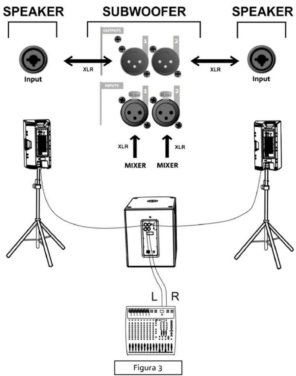
CASO B (collegamento STEREO fra un subwoofer e 2 speaker, figura 3)
SUB 600 series Cod. 420120251 REV. 1.1

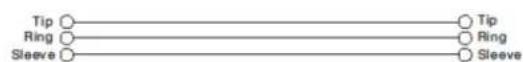
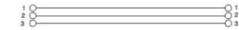
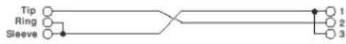
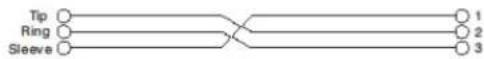
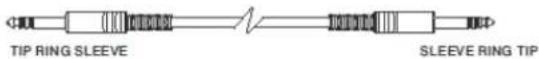
Balanced


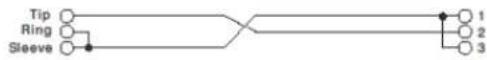
Unbalanced


SUB 600 series Cod. 420120251 REV. 1.1
3. ESEMPI DI UTILIZZO

SUB 600 series Cod. 420120251 REV. 1.1
4. ACCESSORI
| Controlli: | Subwoofer level, Outputs Mode, Polarity, Subwoofer Mode |
INGRESSI E USCITE
| Ingressi: | 2 x XLR Balanced Inputs |
| Uscite: | 2x XLR Balanced Outputs |
SUB 600 series Cod. 420120251 REV. 1.1
DIMENSIONI
USAGE ON SUBWOOFER WITH POLE TELESCOPIC 30
4 ACCESSORIES 31
5.TROUBLESHOOTING 32
6. SPECIFICATIONS 33
GENERAL 33
ACOUSTICAL SPECIFICATIONS 33
AMPLIFIER 33
PROCESSOR 34
USER INTERFACE 34
INPUTS & OUTPUTS 34
POWER SUPPLY SPECIFICATIONS (ABSORPTION / INSTALLATION) 34
DIMENSIONS 35
1. GENERAL INFORMATION
WELCOME!
Thanks for purchasing a product designed and developed in Italy by dBTechnologies! This ergonomic and versatile active subwoofer is the result of a long experience in the sound reinforcement industry, making use of optimized sound, electronic and material research solutions.
PRODUCT OVERVIEW
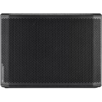
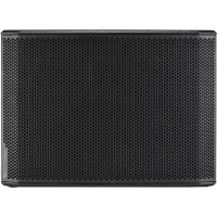
The new SUB 600 subwoofoers are equipped with a 12" woofer (SUB 612), 15" woofer (SUB 615) and an 18" woofer (SUB 618), respectively. Accurate design and sound optimisation allow for high-quality performance in a compact product. Cabinets high ergonomics and ease of handling make them easy to transport.
SUB 600 main features are:
- an ergonomic, compact and versatile project, for both indoors and outdoors
- wooden cabinets for acoustic performance optimisation, with resistant external surfaces for both indoor and outdoor use
- reliable, silent digital amplifier
- mono/stereo input
- mono/stereo output
- dedicated DSP controls, with Polarity, Output Mode, and equalisation button (Subwoofer Mode)
USER REFERENCE
To make the most of your subwoofer, we recommend that you:
- Read the quick start user manual included in the package and this user manual thoroughly and keep this manual during the whole life of the product.
- Register your product at http://www.dbtechnologies.com under "SUPPORT".
- Keep proof of purchase and WARRANTY (User manual "section 2").
MECHANICAL AND ACOUSTICAL FEATURES
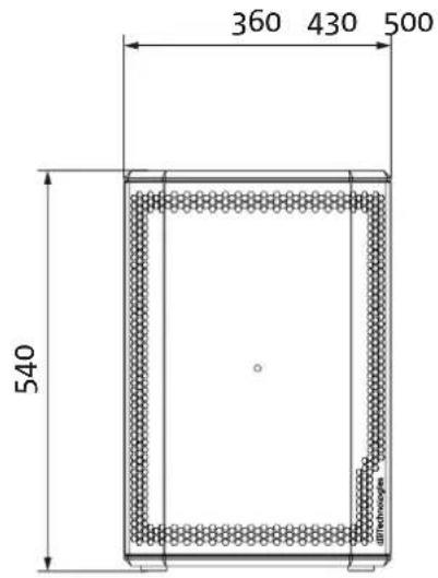
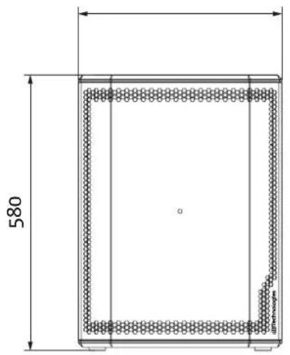
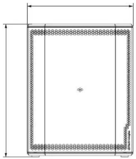
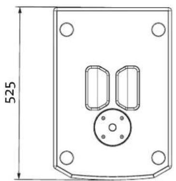
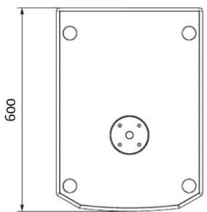
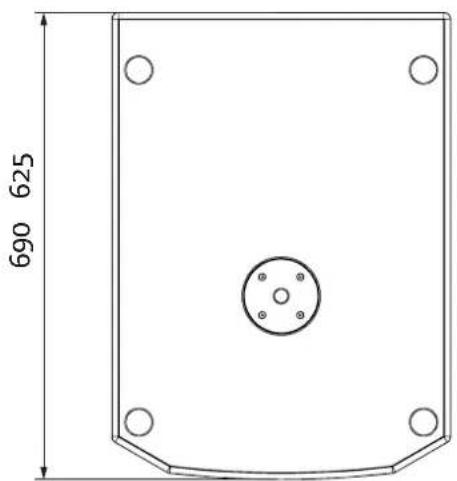
DIMENSIONS
SUB 600 have the following sizes:
SUB 612: 360× 540× 525 (mm)
SUB 615: 430× 580× 600(mm)
SUB 618: 500× 625× 690 (mm)
SUB 600 series Cod. 420120251 REV. 1.1
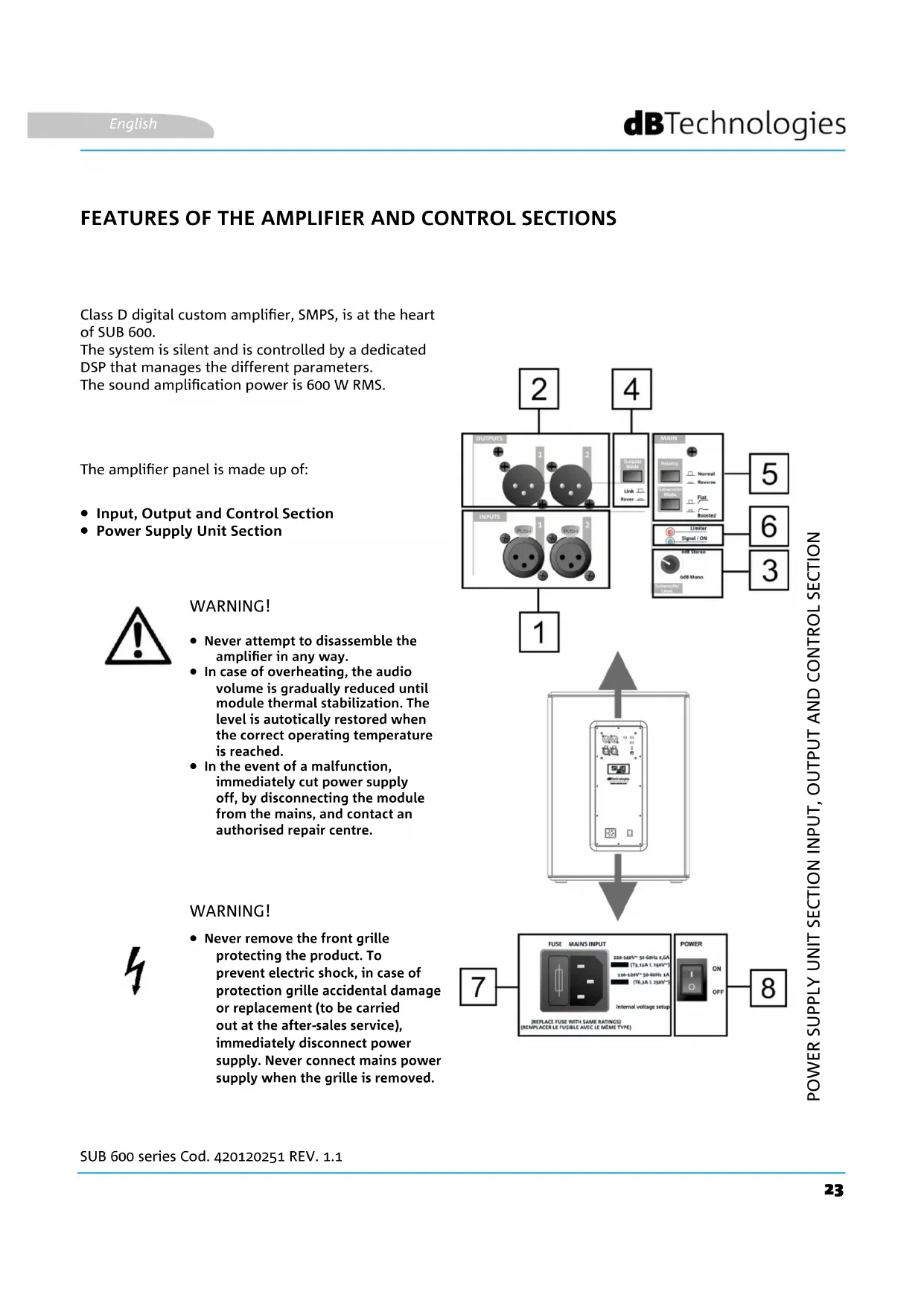
FEATURES OF THE AMPLIFIER AND CONTROL SECTIONS
Class D digital custom amplifier, SMPS, is at the heart of SUB 600.
The system is silent and is controlled by a dedicated DSP that manages the different parameters.
The sound amplification power is 600 W RMS.
The amplifier panel is made up of:
- Input, Output and Control Section
Power Supply Unit Section

WARNING!
- Never attempt to disassemble the amplifier in any way.
- In case of overheating, the audio volume is gradually reduced until module thermal stabilization. The level is automatically restored when the correct operating temperature is reached.
- In the event of a malfunction, immediately cut power supply off, by disconnecting the module from the mains, and contact an authorised repair centre.
WARNING!
- Never remove the front grille protecting the product. To prevent electric shock, in case of protection grille accidental damage or replacement (to be carried out at the after-sales service), immediately disconnect power supply. Never connect mains power supply when the grille is removed.
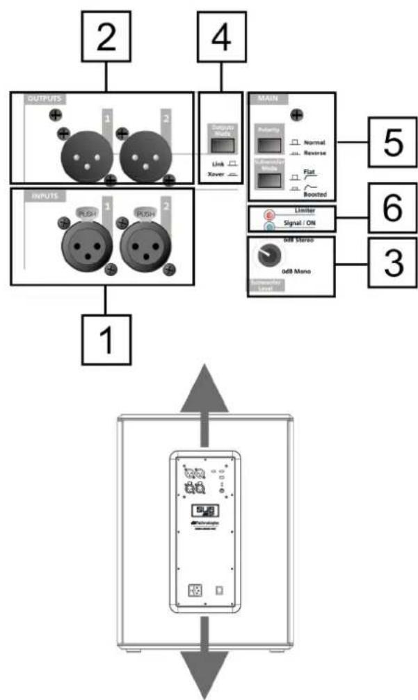

INPUT, OUTPUT AND CONTROL SECTION
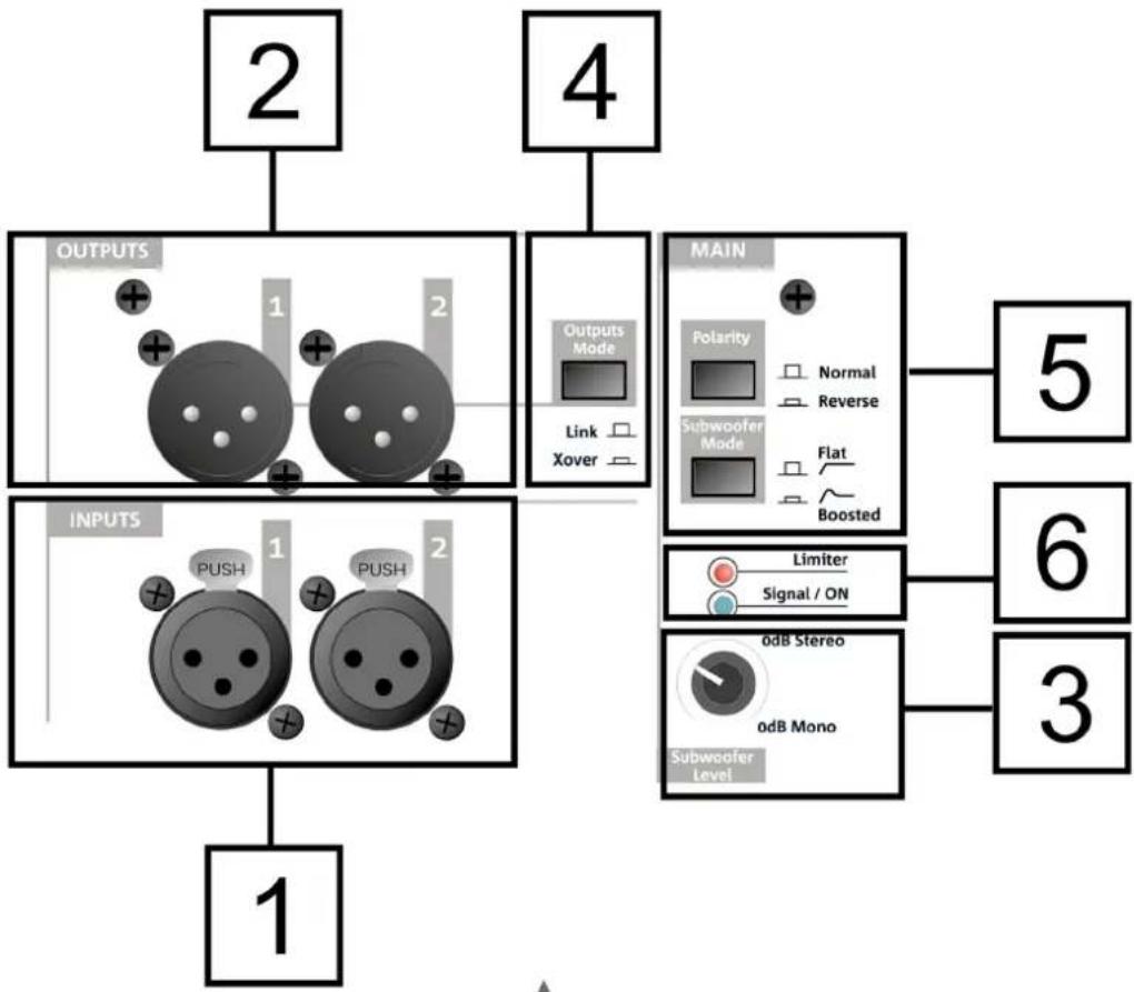
1. INPUTS
XLR (balanced) input connectors. They may be used for mono or stereo connection. For further details concerning connection, refer to INPUT CONNECTIONS AND AUDIO DAISY CHAIN.
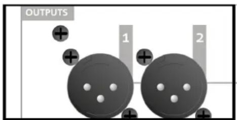
2. OUTPUTS
XLR (balanced) output connectors. They may be used for mono or stereo connection. For further details concerning connection, refer to INPUT CONNECTIONS AND AUDIO DAISY CHAIN.
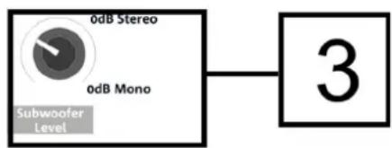
3. Subwoofer Level
Rotary switch to adjust output audio level.
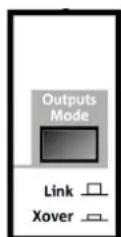
4. Outputs Mode
Selector allowing to set the type of output signal (Link/Xover). It acts on the daisy-chained signal from OUTPUT connectors [2].
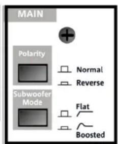
5. Polarity and Subwoofer Mode buttons
Buttons allowing to control (Normal or Reverse) Polarity and the type of output filtering (Flat, i.e. without equalisation, Boosted, i.e. low frequencies are emphasised).
6. LED (Limiter, Signal/ON)
Indicator LEDs. The Limiter LED turns on when the internal protection circuit is triggered, while Signal/ON indicates subwoofer power-up as well as the presence of an input audio signal.
SUB 600 series Cod. 420120251 REV. 1.1
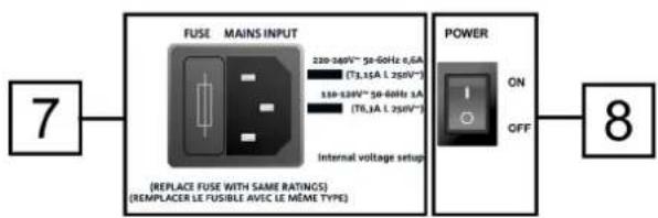
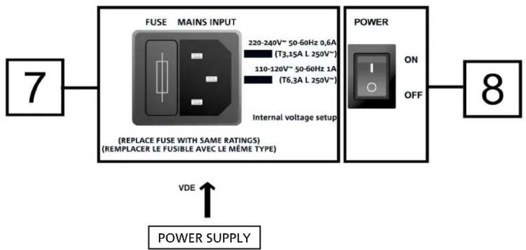
POWER SUPPLY UNIT SECTION
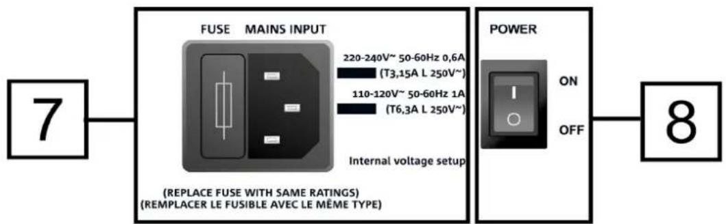
7. MAINS INPUT
VDE connector input. For connection to the mains, through the cable supplied with the device.
The FUSE section contains mains fuse housing.
8. POWER
Switch for turning device ON or OFF.
2. FIRST POWER-UP
The package of SUB 600 subwoofer contains:
- 612 or 615 or 618 subwoofer
VDE power cable - quick start user manual and warranty documents in hard copy
CONFIGURATION AND OPTIMISATION
SUB 600, used in a stand-alone configuration, are characterised by omnidirectional sound emission. This feature is emphasised in case of low frequencies, while it decreases as frequency increases.
For subwoofer use optimisation in given configurations, the control panel displays the following:
-
Outputs Mode:
-
Link (the signal present at OUTPUTS is the one applied to the woofer)
- Xover (the signal present at OUTPUTS is filtered with a crossover frequency of 120Hz , for daisy chain to a speaker, such as B-HYPE and OPERA)
Polarity:
- Normal (audio signal normal polarity)
-
Reverse (reverse polarity, useful for wavefront optimisation through acoustic wave phase reversal)
-
Subwoofer Mode:
-
Flat (sound emission without equalisation)
- Boosted (sound emission is emphasised in case of low frequencies)
Before power-up, set Subwoofer Level selector [3] to 0 dB (Mono or Stereo, depending on the configuration).
SUB 600 series Cod. 420120251 REV. 1.1
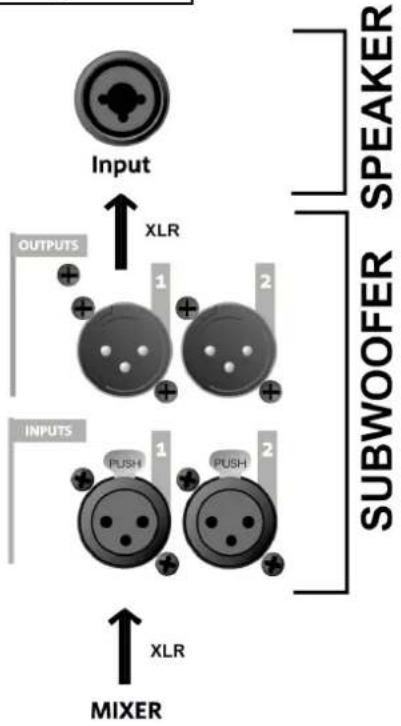
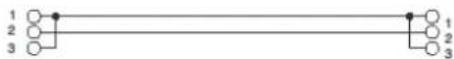
INPUT CONNECTIONS AND AUDIO DAISY CHAIN
According to the specific configuration (mono or stereo), one or two cables (not supplied) are required at input and at daisy chain. XLR connectors are required.
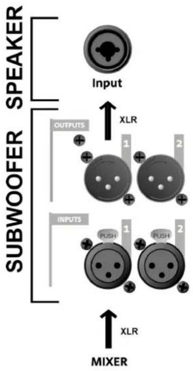
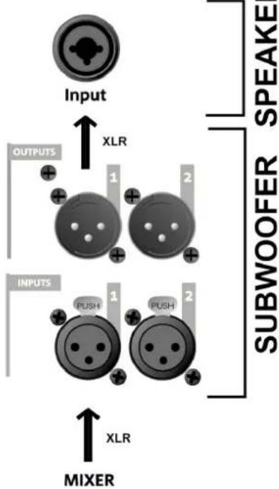
CASE A (MONO connection) between subwoofer and speaker (examples: figure 1, figure 2):
In the event of a MONO connection between subwoofer and speaker:
- Connect mixer output to subwoofer INPUTS 1 connector
- Connect subwoofer OUTPUTS 1 connector to speaker input.
- For each speaker, select the type of input impedance on LINE.
- For each channel in the configuration, set subwoofer OUTPUTS MODE [4] to XOVER, in order to daisy-chain a signal having a crossover frequency of 120Hz to the speaker.
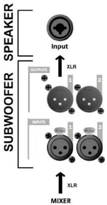
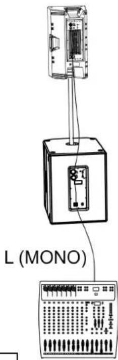
Figure 1
SUB 600 series Cod. 420120251 REV. 1.1
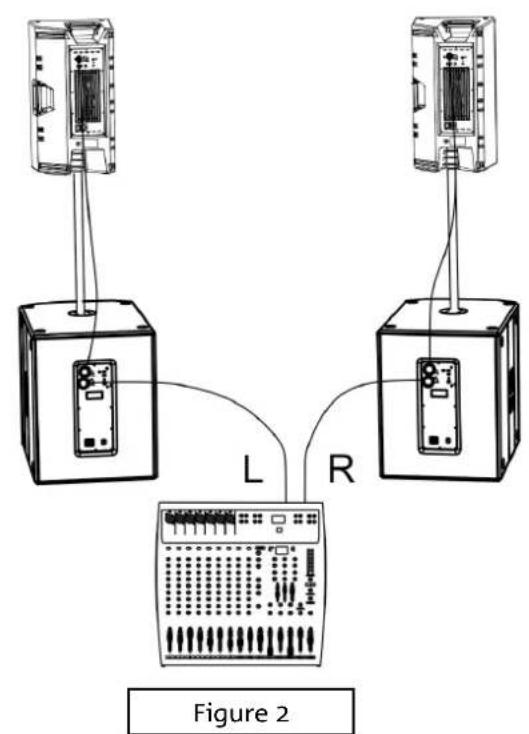
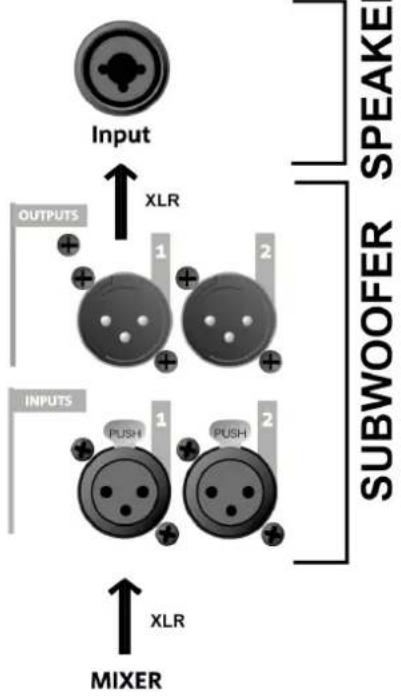
CASE B (STEREO connection between a subwoofer and 2 speakers, figure 3)
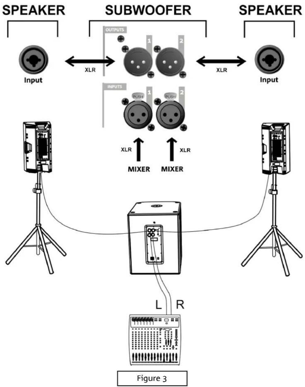
- Connect mixer L, R outputs to subwoofer INPUTS 1 and 2 respectively.
- Daisy-chain the signal to the speakers, connecting OUTPUTS 1 to LH speaker Input, OUTPUTS 2 to RH speaker Input.
- Select the impedance for each speaker ("LINE" type).
- Set subwoofer OUTPUTS MODE [4] to XOVER, in order to daisy-chain a signal having a crossover frequency of 120Hz to the speaker.
SUB 600 series Cod. 420120251 REV. 1.1
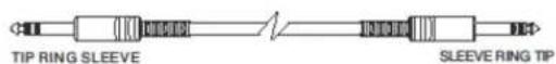
Balanced


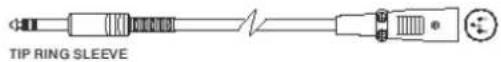
Unbalanced


POWER SUPPLY CONNECTION
For power supply connection of the device, insert the connector of the supplied cable into "MAINS INPUT" [7]. Then insert the plug into an outlet having a proper earth conductor. Switch the POWER selector [8] to "ON".
SUB 600 series Cod. 420120251 REV. 1.1
3. USAGE EXAMPLES

- Types of installation other than those here described are not allowed.
- Never use the handles to suspend the subwoofer
- Always check that the positioning is stable and that the installation does not pose a danger to people, animals or property.
FLOOR USAGE
SUB 600 may be used directly on the floor (see figure opposite showing a usage example.)
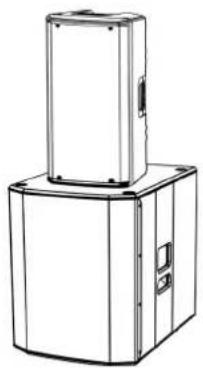
USAGE WITH SPEAKER IN A STACK
A speaker may be installed directly on the subwoofer by means of a DS2-S 35 mm diameter mini-pole (e.g. series: INGENIA, B-HYPE, OPERA).
INGENIA series allows for 2 stacked speakers (specific accessories: LP-IG and GSA-IG/GSA-IGA). In particular, in the event of 2 stacked INGENIA IG3T or 2 stacked INGENIA IG4T, fastening by means of additional belts is required to ensure stable and safe installation.
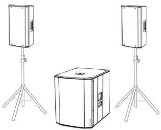
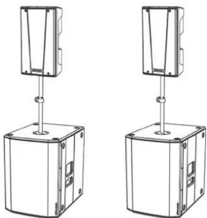
USAGE ON SUBWOOFER WITH POLE TELESCOPIC
It is possible to use only one speaker mounted on a 35mm diameter pole (e.g. series: OPERA, B-HYPE). The reference accessory is DS-2 (telescopic pole).
The maximum allowed height between the speaker base and the floor is 165~cm except for B-HYPE 15 and OPERA 15, whose maximum allowed height is 120~cm .
SUB 600 series Cod. 420120251 REV. 1.1
4. ACCESSORIES
To completion of the series, the following accessories are provided as options:
Protection covers
Check the new compatible accessories on: www.dbtechnologies.com
5. TROUBLESHOOTING
The subwoofer will not turn on:
- Check that power supply is present upstream of the installation.
- Ensure that the power supply cable with VDE connector is properly plugged in.
The subwoofer turns on but produces no sound:
- Check that the input connection of the audio signal is correctly performed.
- Check the cables for damage.
- Ensure that the mixer or audio source is on and an output signal is present.
- Check the general level through the "Subwoofer Level" control.
Speaker sound is inappropriate:
- Check the cables for damage and replace them as required (a damaged cable may lead to signal loss or alteration).
- Ensure that Outputs Mode, Polarity and Subwoofer Mode selection settings are correct according to the selected configuration.
6. SPECIFICATIONS
GENERAL
| Type: | Active subwoofer |
ACOUSTICAL SPECIFICATIONS
| Frequency response [-10dB]: | 46 - 123 Hz (SUB 612) / 42 - 124 Hz (SUB 615) / 35 -130 Hz (SUB 618) |
| Max SPL (1m): | 129 dB (SUB 612) / 131 dB (SUB 615) / 133 dB (SUB 618) |
| LF: | 12” (SUB 612) / 15” (SUB 615) / 18” (SUB 618) |
| LF voice coil: | 2.5” |
| Crossover frequency: | 120 Hz |
AMPLIFIER
| Type: | AMP SMPS |
| Amplification class | Class D |
| Power supply | 1 x VDE |
| RMS amplifier power: | 600 W |
PROCESSOR
| Internal controller: | 28-bit/56-bit DSP |
| Limiter: | Peak, RMS, Thermal |
USER INTERFACE
| Controls: | Subwoofer level, Outputs Mode, Polarity, Subwoofer Mode |
INPUTS & OUTPUTS
| Inputs: | 2 x XLR Balanced Inputs |
| Outputs: | 2x XLR Balanced Outputs |
POWER SUPPLY SPECIFICATIONS (ABSORPTION / INSTALLATION)
| Absorption at 1/8th of power in medium use conditions (*): | 0.9 A (220-240V~) - 1.6 A (110-120V~) |
| Absorption at 1/3rd of power in maximum use conditions (**): | 1.7 A (220-240V~) - 2.8 A (110-120V~) |
| Absorption with speaker on in no-signal condition (idle): | 16 W |
| Inrush current: | 17.9 A |
* NOTE FOR INSTALLER: Values refer to 1/8th of power, under average operating conditions (music programme with occasional or no clipping). For any type of configuration we recommend to consider them as minimum sizing values.
** NOTE FOR INSTALLER: Values refer to 1/3rd of power, under heavy operating conditions (music programme with frequent clipping and limiter activation). In case of professional installations and tours we recommend sizing according to these values.
SUB 600 series Cod. 420120251 REV. 1.1
DIMENSIONS
| Material: | Multilayer wood (with protective black paint) |
| Grille: | NC-machined |
| Handles: | 2, on sides |
| Pole mount: | Yes, 36 mm (provision: M20) |
| Width: | 360 mm (SUB 612) / 430 mm (SUB 615) / 500 mm (SUB 618) |
| Height: | 540 mm (SUB 612) / 580 mm (SUB 615) / 625 mm (SUB 618) |
| Depth: | 525 mm (SUB 612) / 600 mm (SUB 615) / 690 mm (SUB 618) |
| Weight: | 19.8 kg (SUB 612) / 25.5 kg (SUB 615) / 31.1 kg (SUB 618) |
Product features, specifications and appearance are subject to changes without prior notice. dBTechnologies reserves the right to make changes or improvements in design or manufacture without any obligation to incorporate such changes or improvements in products manufactured before their introduction.

A.E.B. Industriale Srl
Via Brodolini, 8
6. LED (Limiter, Signal/ON)
6. LED (Limiter, Signal/ON)
| Commands: | Subwoofer level, Outputs Mode, Polarity, Subwoofer Mode |
ENTRÉES ET SORTIES
| Entrées : | 2 x XLR Balanced Inputs |
| Sorties : | 2x XLR Balanced Outputs |
SPECIFICATIONS D'ALIMENTATION (ABSORPTION / INSTALLATION)
SUB 600 series Cod. 420120251 REV. 1.1
CHARACTERISTICAS DE LA SECCION DE AMPLIFICACION Y CONTROL
6. LED (Limiter, Signal/ON)
SUB 600 series Cod. 420120251 REV. 1.1
CONEXION DE LAS ENTRADAS Y TRANSMISION AUDIO
SUB 600 series Cod. 420120251 REV. 1.1
SUB 600 series Cod. 420120251 REV. 1.1

Balanced


Unbalanced


SUB 600 series Cod. 420120251 REV. 1.1
3. EJEMPLOS DE USO

USO CON ALTAVOCES EN STACK
SUB 600 series Cod. 420120251 REV. 1.1
4. ACCESSORIES
SUB 600 series Cod. 420120251 REV. 1.1
PROCESADOR
| Controles: | Subwoofer level, Outputs Mode, Polarity, Subwoofer Mode |
ENTRADAS Y SALIDAS
| Entradas: | 2 x XLR Balanced Inputs |
| Salidas: | 2x XLR Balanced Outputs |