Opera 15 - Speaker DB Technologies - Free user manual and instructions
Find the device manual for free Opera 15 DB Technologies in PDF.
User questions about Opera 15 DB Technologies
0 question about this device. Answer the ones you know or ask your own.
Ask a new question about this device
Download the instructions for your Speaker in PDF format for free! Find your manual Opera 15 - DB Technologies and take your electronic device back in hand. On this page are published all the documents necessary for the use of your device. Opera 15 by DB Technologies.
USER MANUAL Opera 15 DB Technologies
natural_image
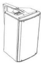
Line drawing of a rectangular electronic device with a lid and handle (no text or symbols)OPERA10
natural_image
Line drawing of a rectangular enclosure with a lid and mounting holes (no text or symbols)OPERA12
natural_image
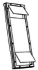
Line drawing of a rectangular electronic device with mounting holes and a side panel (no text or symbols)OPERA15
USER MANUAL - Section 1
The warnings in this manual must be observed together with the "User Manual - Section 2".
According to the standards EN 55103 this equipment is designed and suitable to operate in E3 (or lower E2, E1) Electromagnetic environments.
FCC CLASS B STATEMENT ACCORDING TO TITLE 47, CHAPTER I, SUBCHAPTER A, PART 15, SUBPART B
This equipment has been tested and found to comply with the limits for a Class B digital device, pursuant to part 15 of the FCC Rules. These limits are designed to provide reasonable protection against harmful interference in a residential installation. This equipment generates, uses and can radiate radio frequency energy and, if not installed and used in accordance with the instructions, may cause harmful interference to radio communications. However, there is no guarantee that interference will not occur in a particular installation. If this equipment does cause harmful interference to radio or television reception, which can be determined by turning the equipment off and on, the user is encouraged to try to correct the interference by one or more of the following measures:
—Reorient or relocate the receiving antenna.
—Increase the separation between the equipment and receiver.
—Connect the equipment into an outlet on a circuit different from that to which the receiver is connected.
—Consult the dealer or an experienced radio/TV technician for help.
Changes or modifications not expressly approved by the party responsible for compliance could void the user's authority to operate the equipment.
WARNING
Make sure that the loudspeaker is securely installed in a stable position to avoid any injuries or damages to persons or properties. For safety reasons di not place one loudspeaker on top of another without proper fastening systems. Before hanging the loudspeaker check all the components for damages, deformations, missing or damaged parts that may compromise safety during installation. If you use the loudspeakers outdoor avoid spots exposed to bad weather conditions.
Contact dBTechnologies for accessories to be used with the speakers. dBTechnologies will not accept any responsibility for damages caused by inappropriate accessories or additional devices.
OPERA10 - OPERA12 - OPERA 15 Cod. 420120247 REV. 1.1
ITALIANO
ENGLISH
DEUTSCH
FRANÇAIS
ESPAÑOL
INDICE
2. PRIMA ACCENSIONE.... 10
INGRESSI E USCITE 18
text_image
Technologics www.technologics-163.com USB Power Power Power Power Power Power Power Power Power Power Power Power Power Power Power Power Power Power Power Power Power Power Power Power Power Power Power Power Power Power Power Power Power Power Power Power Power Power Power Power Power Power Power Power Power Power Power Power Power Power Power Cable
INPUT E CONTROLLO

ALIMENTAZIONE
ATTENZIONE!
text_image
Line Mic Audio Input Sens. MIXER / LINEA 1 Balanced input Line Mic Audio Input Sens. 0dB max DSP Preset Main Limiter Signal / ON 3 Ground 2 Balanced input Line Instr 0dB max Balanced Out Out Routing Selector CRL Link Mic Out 5 DSP Preset Club Vocal Bass Reduction Playback Bass Boost W1 W2 W3 W4 W5 W6 W7 W8 W9 W10 W11 W12 W13 W14 W15 W16 W17 W18 W19 W20 W21 W22 W23 W24 W25 W26 W27 W28 W29 W30 W31 W32 W33 W34 W35 W36 W37 W38 W39 W40 W41 W42 W43 W44 W45 W46 W47 W48 W49 W50 w/o/inv/ Audio Input Sens. Line Instr. dBTechnologies DESIGNED & DEVELOPED IN ITALY. Audio Input Sens. Line Instr. STRUMENTO (ALTA IMPEDENZA)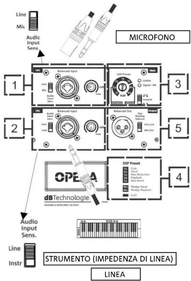
text_image
Line Mic Audic Input Sens. MICROFONO 1 CHL Balanced input Line Mic Audio Input Sens. DSP Preset Main 3 S2 Signal / ON FLAT Ground 2 Chl Balanced input Line Instr DSP Preset Club Vocal Bass Reduction Playback Base Board W1 Vedge Vocal W2 Vedge Playback FLAT 4 OPEA dB Technologie. DESIGNED & DEVELOPED IN ITALY Audio Input Sens. Line Instr STRUMENTO (IMPEDENZA DI LINEA) LINEAtext_image
DSP Preset Main Limitar Signal / ON FLAT Ground 3 STEATER SOURCE Balanced Out Output Out Routing Selector CHS Link Mix Out 5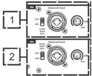
text_image
1 2 Ch1 Balanced Input Line Mio Audio Input Sets. Balanced Input Line Mio Audio Input Sets. Balanced Input Line Mio Audio mox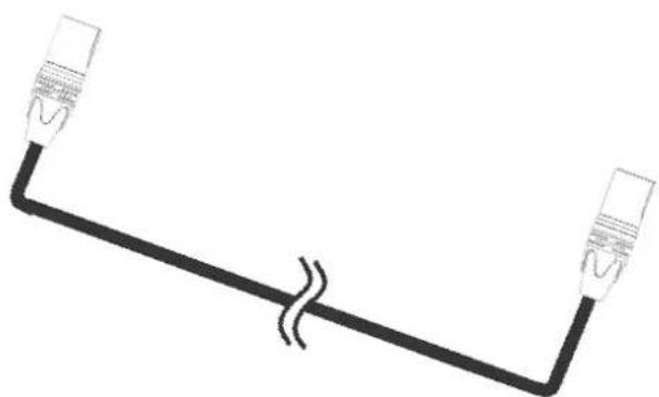
natural_image
Simple line drawing of two connected devices with a double line, no text or symbols present
natural_image
Line drawing of a tripod-mounted device with a rectangular box on top (no text or symbols)INSTALLAZIONE SU SUBWOOFER
natural_image
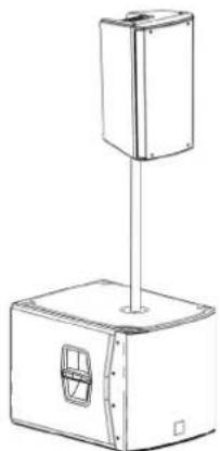
Line drawing of a mechanical device with a square top and rectangular base, featuring a small circular opening (no text or symbols)INSTALLAZIONE SU SUBWOOFER CON PALO
natural_image
Technical line drawing of a mechanical device with a vertical support and base housing (no text or symbols)OPERA10 - OPERA12 - OPERA 15 Cod. 420120247 REV. 1.1
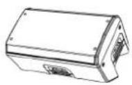
UTILIZZO WEDGE (MONITORING)
natural_image
Line drawing of a mechanical device with triangular supports and a base plate (no text or symbols)natural_image
Line drawing of two identical tripod-mounted scientific instruments or support poles (no text or symbols)SSB2 (COPPIA DI TREPPIEDI)
natural_image
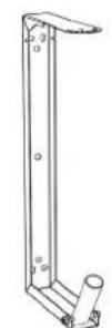
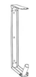
Line drawing of a vertical metal frame with a cylindrical base and mounting holes (no text or symbols)OP-WB (STAFFE A MURO)
natural_image
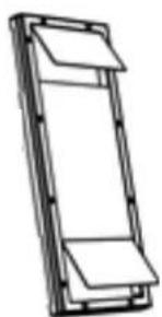
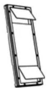
Simple line drawing of a rectangular frame with two horizontal panels, no text or symbols present.RC-M1 (RAIN COVER)

ATTENZIONE!
PRODUCT OVERVIEW.... 21
USER REFERENCE 21
MECHANICAL AND ACOUSTICAL FEATURES.... 22
DIMENSIONS 22
SOUND COVERAGE.... 22
FEATURES OF THE AMPLIFIER AND CONTROL SECTIONS.... 23
INPUT, OUTPUT AND CONTROL SECTION 24
POWER SUPPLY UNIT SECTION 25
2. FIRST POWER-UP 26
PACKAGE CONTENTS 26
USAGE 26
INPUT CONNECTIONS.... 26
POWER SUPPLY CONNECTION 28
CONNECTING THE OUTPUTS OF MULTIPLE MODULES (audio daisy chain) 28
3. USAGE EXAMPLES.... 29
USAGE ON STAND 29
USAGE ON SUBWOOFER.... 29
INSTALLATION ON SUBWOOFER WITH POLE 29
WEDGE (MONITORING) INSTALLATION 30
WALL-MOUNTING WITH BRACKETS 30
INSTALLATION ON TRUSS WITH BRACKETS AND ALISCAFF COUPLERS 30
INSTALLATION WITH EYEBOLTS 30
4. ACCESSORIES.... 31
5. TROUBLESHOOTING 32
6. SPECIFICATIONS 33
GENERAL 33
ACOUSTICAL SPECIFICATIONS.... 33
AMPLIFIER 33
PROCESSOR.... 34
INPUTS.... 34
USER INTERFACE 34
POWER SUPPLY SPECIFICATIONS 34
DIMENSIONS 35
Thanks for purchasing a product designed and developed in Italy by dBTechnologies! This ergonomic and versatile active speaker is the product of several years of experience and innovation in the sound reinforcement industry, using cutting-edge sound, electronic and material research solutions.
PRODUCT OVERVIEW
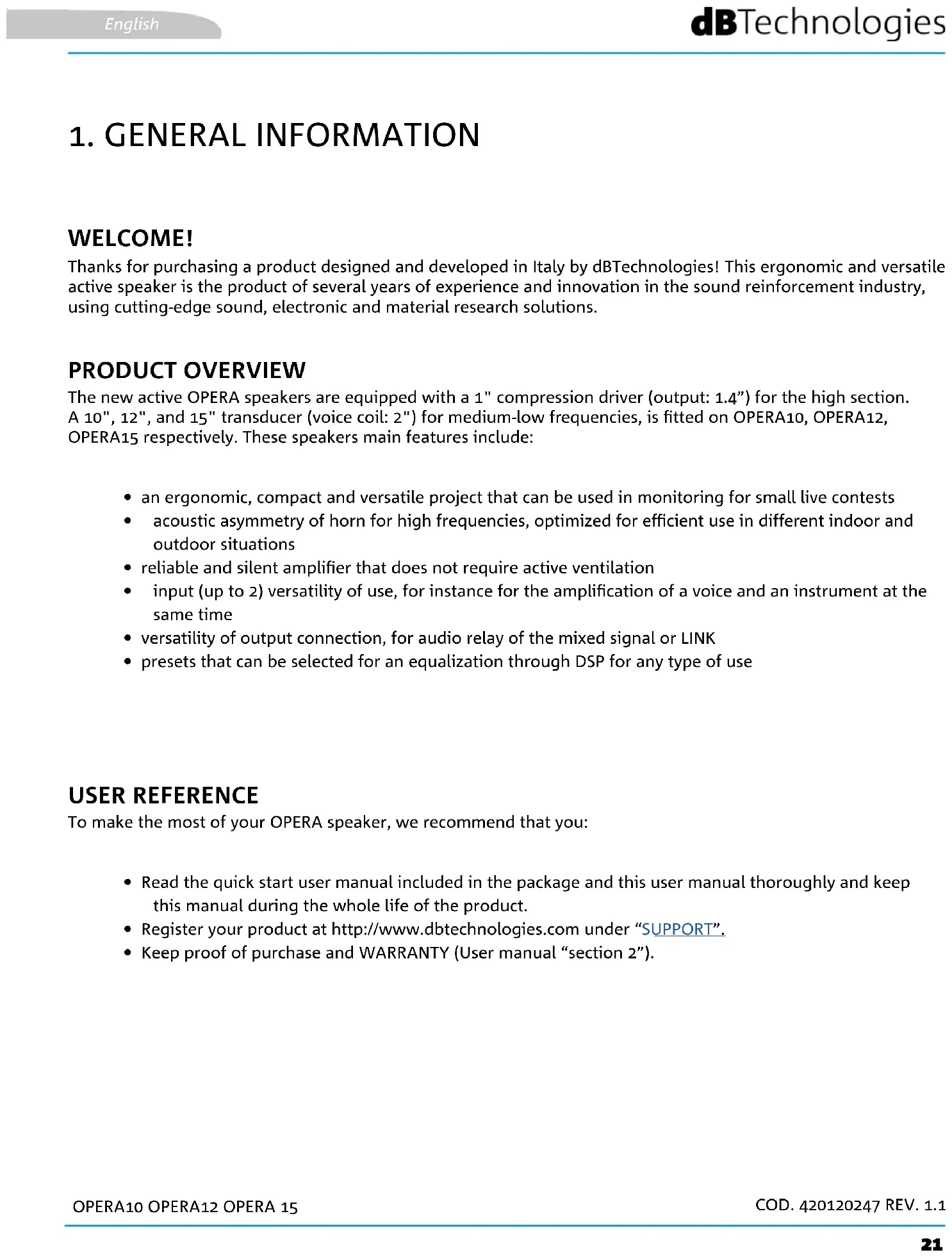
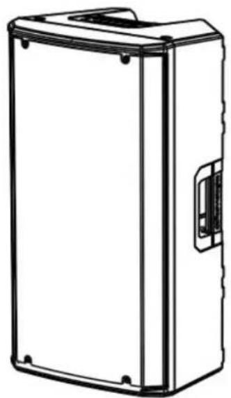
The new active OPERA speakers are equipped with a 1" compression driver (output: 1.4") for the high section. A 10", 12", and 15" transducer (voice coil: 2") for medium-low frequencies, is fitted on OPERA10, OPERA12, OPERA15 respectively. These speakers main features include:
- an ergonomic, compact and versatile project that can be used in monitoring for small live contests
- acoustic asymmetry of horn for high frequencies, optimized for efficient use in different indoor and outdoor situations
- reliable and silent amplifier that does not require active ventilation
- input (up to 2) versatility of use, for instance for the amplification of a voice and an instrument at the same time
- versatility of output connection, for audio relay of the mixed signal or LINK
- presets that can be selected for an equalization through DSP for any type of use
USER REFERENCE
To make the most of your OPERA speaker, we recommend that you:
- Read the quick start user manual included in the package and this user manual thoroughly and keep this manual during the whole life of the product.
- Register your product at http://www.dbtechnologies.com under "SUPPORT".
- Keep proof of purchase and WARRANTY (User manual "section 2").
MECHANICAL AND ACOUSTICAL FEATURES
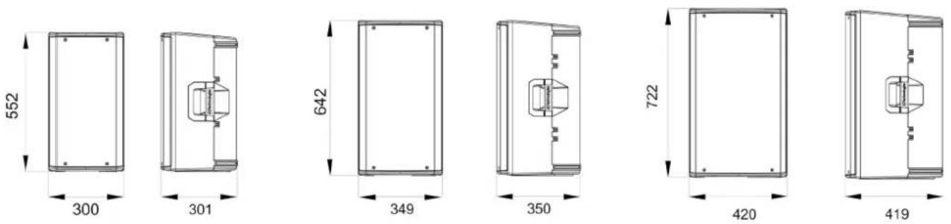
DIMENSIONS
The OPERA series has been designed with the intent to optimise weight and dimensions.
The cabinet is lighter but more resistant, and features 2 handles, one on the side and one at the top, for easy handling.
For a quick comparison of the 3 models, the overall dimensions are the following:
OPERA10 - 300 mm (L), 552 mm (H), 301 mm (W)
OPERA12 - 349 mm (L), 642 mm (H), 350 mm (W)
OPERA15 - 420 mm (L), 772 mm (AH), 419 mm (W)
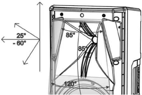
SOUND COVERAGE
The special design of the horn, shown in the figure, is common for all 3 models.
In horizontal, the coverage is differentiated between the value of 85^ (upper part) and 120^ (lower part).
This is to optimise sound emission, for example during vertical installation in reverberant environments.
The special design of the horn, shown in the figure, is common to the 3 models. The overall vertical opening (85°) is asymmetrical, to increase the sound pressure of the horn at long distance.
In case of use with monitoring function or in case of horizontal positioning (wall-mounted) of the speaker, take these data into account so as to calculate the correct coverage of the environment.
text_image
25° -60° 85° 85° 120°Class D digital amplifier is at the heart of the OPERA series. The system is silent and does not require a fan cooling. The system is controlled by a dedicated powerful DSP that manages the different parameters.
The sound amplification power is 600 W RMS for all models.

WARNING!
- Protect the unit from moisture.
- Never attempt to disassemble the amplifier in any way.
- In the event of a malfunction, remove power supply immediately by disconnecting the unit from the power mains and contact an authorised repair centre.
text_image
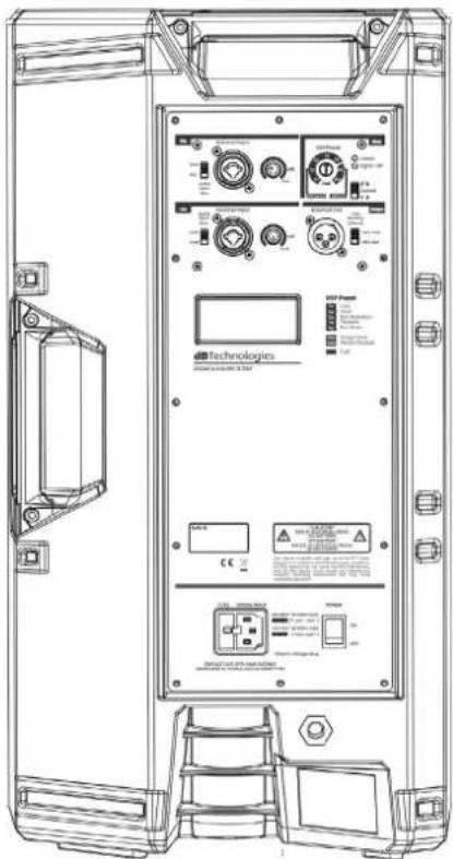
Technologies Power Control DCI Control DCI Control DCI Control DCI Control DCI Control DCI Control DCI Control DCI Control DCI Control DCI Control DCI Control DCI Control DCI Control DCI Control DCI Control DCI Control DCI Control DCI Control DCI Control DCI Control DCI Control DCI Control DCI Control DCI Control DCI Control DCi Control DCi Control DCi Control DCi Control DCi Control DCi Control DCi Control DCi Control DCi Control DCi Control DCi Control DCi Control DCi Control DCi Control DCi Control DCi Control DCi Control DCi Control DCi Control DCi Control DCi Control DCi Control DCi Control DCi Control DCi Control DC i Control DC i Control DC i Control DC i Control DC i Control DC i Control DC i Control DC i Control DC i Control DC i Control DC i Control DC i Control DC i Control DC i Control DC i Control DC i Control DC i Control DC i Control DC i Control DC i Control DC i Control DC i Control DC i Control DC i Control DC i Control DCi Control DCi Control DCi Control DCi Control DCi Control DCi Control DCi Control DCi Control DCi Control DCi Control DCi Control DCi Control DCi Control DCi Control DCi Control DCi Control DCi Control DCi Control DCi Control DCi Control DCi Control DCi Control DCi Control DCi Control DC_i Control DC_i Control DC_i Control DC_i Control DC_i Control DC_i Control DC_i Control DC_i Control DC_i Control DC_i Control DC_i Control DC_i Control DC_i Control DC_i Control DC_i Control DC_i Control DC_i Control DC_i Control DC_i Control DC_i Control DC_i Control DC_i Control DC_i Control DC_i Control DC_i Control DC_{10} - DC_{11} - DC_{12} - DC_{13} - DC_{14} - DC_{15} - DC_{16} - DC_{17} - DC_{18} - DC_{19} - DC_{20} - DC_{21} - DC_{22} - DC_{23} - DC_{24} - DC_{25} - DC_{26} - DC_{27} - DC_{28} - DC_{29} - DC_{30} - DC_{31} - DC_{32} - DC_{33} - DC_{34} - DC_{35} - DC_{36} - DC_{37} - DC_{38} - DC_{39} - DC_{40} - DC_{41} - DC_{42} - DC_{43} - DC_{44} - DC_{45} - DC_{46} - DC_{47} - DC_{48} - DC_{49} - DC_{50} - DC_{51} - DC_{52} - DC_{53} - DC_{54} - DC_{55} - DC_{56} - DC_{57} - DC_{58} - DC_{59} - DC_{60} - DC_{61} - DC_{62} - DC_{63} - DC_{64} - DC_{65} - DC_{66} - DC_{67} - DC_{68} - DC_{69} - DC_{70} - DC_{71} - DC_{72} - DC_{73} - DC_{74} - DC_{75} - DC_{76} - DC_{77} - DC_{78} - DC_{79} - DC_{80} - DC_{81} - DC_{82} - DC_{83} - DC_{84} - DC_{85} - DC_{86} - DC_{87} - DC_{88} - DC_{89} - DC_{90} - DC_{91} - DC_{92} - DC_{93} - DC_{94} - DC_{95} - DC_{96} - DC_{97} - DC_{98} - DC_{99} - DC_000The DIGIPRO G3 panel is made up of:
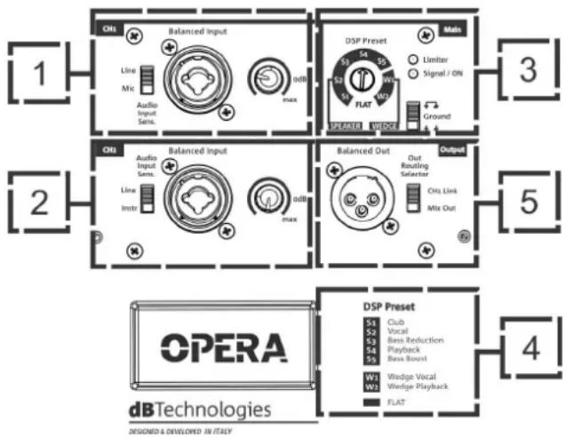
- Input, Output and Control Section
• Power Supply Unit Section
WARNING!
- Never remove the product's front protection mesh. In order to prevent electric shock hazard, in the event of accidental damage or replacement of the protection mesh (which must be carried out by a service center), disconnect the power supply immediately. Do not connect to the power supply while the mesh has been removed.
Equipped with a Combo connector to connect cables with both XLR and TRS connectors (balanced and unbalanced), it includes the regulation of the channel level and a switch to adapt the impedance to line level ("Line"), or to microphone level ("Mic").
2. "CH2" INPUT SECTION
Provided with Combo connector to connect cables with XLR and TRS (balanced and unbalanced) connectors, includes channel level adjustment and a switch to adjust input impedance (“Line” or “Instr”). “Instr” refers to a high impedance such as that of a guitar or bass.
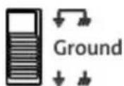
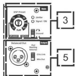
3. "Main" GENERAL SETUP SECTION
It includes the 8-position "DSP Preset" rotary switch, the "Limiter" and "Signal / ON" LED indicators and the "ground lift" switch.
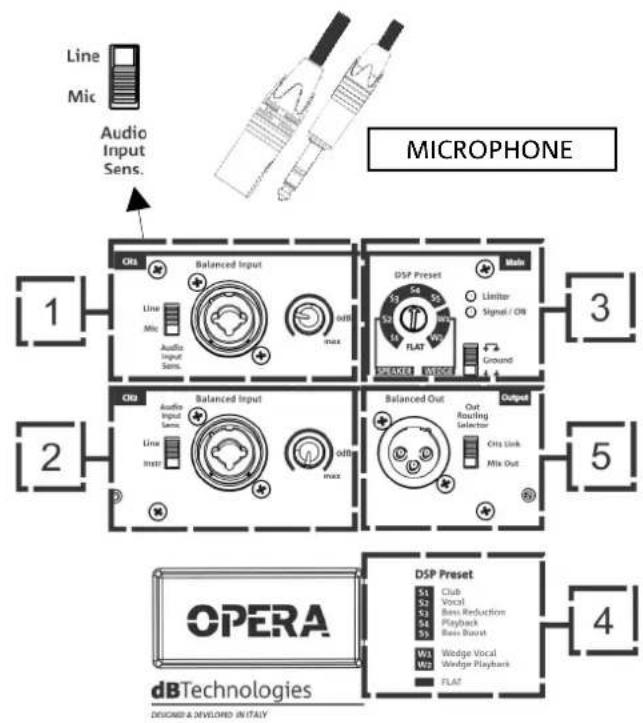
4. DSP PRESET - TABLE
The selectable presets are shown in this table as a reminder.
S1 - Club, suitable for a medium-small indoor environment
S2 - Vocal, optimises for vocal playback and performance
S3 - Bass reduction, with attenuation of low frequencies, for use in reverberant environments
S4 - Playback, optimised for music playback (such as MP3 reader)
S5 - Bass boost, suitable to emphasise low frequencies
Recommended presets for monitor use (wedge):
W1 - Wedge Vocal, to be used with monitor (wedge) position and vocal performance
W2 - Wedge Playback, to be used in monitor (wedge) position and playback of a music programme
Preset that excludes any equalization:
FLAT - to be set if no equalization is required
5. "Output" SECTION
Equipped with connector for balanced cable (XLR), it also includes the
"Out Routing Selector", required to differentiate the output inputs in case of connection to a second speaker.
text_image
1 2 3 4 5 6 7 8 9 10 11 12 13 14 15 16 17 18 19 20 21 22 23 24 25 26 27 28 29 30 31 32 33 34 35 36 37 38 39 40 41 42 43 44 45 46 47 48 49 50 51 52 53 54 55 56 57 58 59 60 61 62 63 64 65 66 67 68 69 70 71 72 73 74 75 76 77 78 79 80 81 82 83 84 85 86 87 88 89 90 91 92 93 94 95 96 97 98 99 100Input for VDE connector for connection to the mains.
6. ON/OFF SWITCH
Switch for turning device ON or OFF.
WARNING!

Do not use the speaker for long periods of time when the Limiter LED is steady on or constantly blinking, as this indicates that the module is operating under excessive stress under distortion conditions.
Use only high quality and in good condition cables. The use of poor quality or damaged cables could affect speaker operation.
2. FIRST POWER-UP
PACKAGE CONTENTS
Check that the package content of the OPERA 10 \ OPERA 12 \ OPERA 15 speaker is complete. The package contains:
• OPERA speaker
• VDE power cable
- quick start user manual and warranty documents
USAGE
INPUT CONNECTIONS
flowchart
graph TD
    A["Line Mic Audio Input Sens."] --> B["MIXER / LINE"]
    B --> C["1"]
    B --> D["2"]
    B --> E["3"]
    B --> F["5"]
    B --> G["4"]
    C --> H["OBL Balanced Input"]
    D --> I["OBL Balanced Input"]
    E --> J["OBL Balanced Input"]
    F --> K["OBL Balanced Input"]
    G --> L["DSP Preset Main"]
    G --> M["Output"]
    H --> N["Line Mic Audio Input Sens."]
    I --> O["Line Mic Audio Input Sens."]
    J --> P["Line Mic Audio Input Sens."]
    K --> Q["Line Mic Audio Input Sens."]
    L --> R["Line Mic Audio Input Sens."]
    M --> S["Line Mic Audio Input Sens."]
    N --> T["Line Instr Audio Input Sens."]
    O --> U["Line Instr Audio Input Sens."]
    P --> V["Line Instr Audio Input Sens."]
    Q --> W["Line Instr Audio Input Sens."]
    R --> X["Line Instr Audio Input Sens."]
    S --> Y["Line Instr Audio Input Sens."]
    T --> Z["Line Instr Audio Input Sens."]
    U --> AA["Line Instr Audio Input Sens."]
    V --> AB["Line Instr Audio Input Sens."]
    W --> AC["Line Instr Audio Input Sens."]
    X --> AD["Line Instr Audio Input Sens."]
    Y --> AE["Line Instr Audio Input Sens."]
    Z --> AF["Line Instr Audio Input Sens."]
    AA --> AG["Line Instr Audio Input Sens."]
    AB --> AH["Line Instr Audio Input Sens."]
    AC --> AI["Line Instr Audio Input Sens."]
    AD --> AJ["Line Instr Audio Input Sens."]
    AE --> AK["Line Instr Audio Input Sens."]
    AF --> AL["Line Instr Audio Input Sens."]
    AG --> AM["Line Instr Audio Input Sens."]
    AH --> AN["Line Instr Audio Input Sens."]
    AI --> AO["Line Instr Audio Input Sens."]
    AJ --> AP["Line Instr Audio Input Sens."]
    AK --> AQ["Line Instr Audio Input Sens."]
text_image
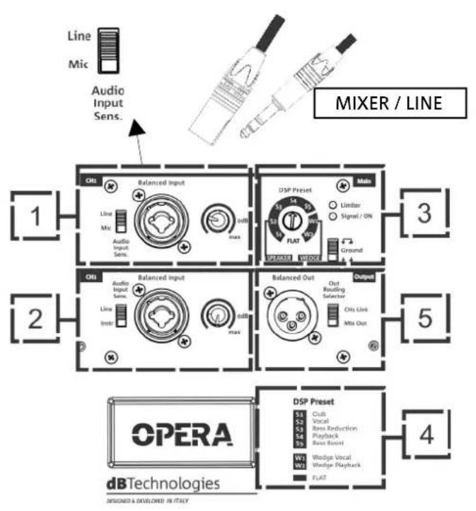
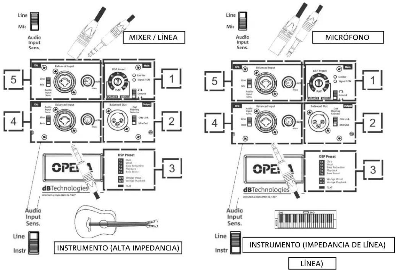
Line Mic Audio Input Sens. MICROPHONE 1 2 3 4 5 OPERA dBTechnologies DESIGNED A DEVELOPED IN ITALY DSP Preset S1 Club S2 Vocal S3 Bass Reduction S4 Playback S5 Bass Burst W03 Wedge Vocal W2 Wedge Playback FLATIt is possible to connect up to 2 inputs in the input and control section at the back of the speaker. Following are only few examples of configuration used (1 input and 2 inputs).
CH1 (1): it is possible to connect a source through a cable with balanced or unbalanced connector (TRS, XLR). Select the input type using the Input Sensitivity Switch. In particular, in case of microphone input, select "MIC".
CH2 (2): it is possible to connect a source through a cable with balanced or unbalanced connector (TRS, XLR). Select the input type using the Input Sensitivity Switch. In particular, in case of input with high impedance, such as the one of a guitar or a bass guitar, select "Instr". Instruments or devices with line impedance (such as a keyboard or a stereo player) require instead a "LINE" setting.
Adjust the level of each connected channel.
Once inputs are connected, select the correct DSP preset (1).
In case of problems related to ground loops, it is possible to solve the problem by setting the relevant selector (3) to the correct position, as shown below.
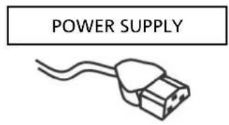
POWER SUPPLY CONNECTION
- Connect the power cable to the socket (7), then set the turning on selector (6) to ON. The Limiter LED (3) blinks briefly.
text_image
POWER SUPPLY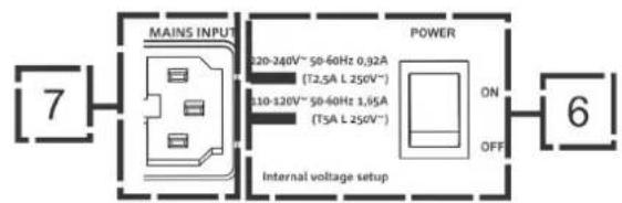
text_image
MAINS INPUT 120-240V~ 50-60Hz 0,92A (T2,5A L 250V~) 110-120V~ 50-60Hz 1,85A (T5A L 250V~) POWER ON OFF 7 6 Internal voltage setupCONNECTING THE OUTPUTS OF MULTIPLE MODULES (audio daisy chain)
text_image
DSP Preset Main Limitar Signal / ON FLAT Ground SEATED SOURCE Balanced Out Output Out Routing Selector CHs Link Mix Out 3 5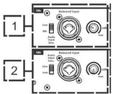
text_image
CN1 Balanced Input Line Min Audio Input Sens. max CN2 Balanced Input Line min Audio Input Sens. max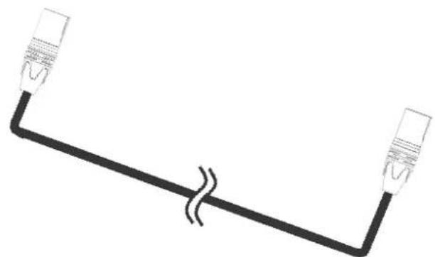
natural_image
Simple line drawing of two connected devices with a double line (no text or symbols)
text_image
OPERA dbTechnologies DESIGNED & DEVELOPED IN ITALYIt is possible to connect the output of an OPERA speaker to a second speaker using a cable with XLR balanced connector, which connects the output (2) of the first speaker to the input (5) or (4) of the second speaker. Set the relevant selector to "LINE".
The Out Routing Selector (2) in "CH1 link" position allows providing the output of the second speaker with only the signal coming from the CH1 (5) channel. In the "Mix Out" position, it allows the CH1 (5) and CH2 (1) channel mixing.

WARNING!
Use only good quality cables.
Replace any damaged cable to prevent malfunctioning and sound poor quality.
- Types of installation other than those here described are not allowed.
- Never use the handles to suspend the speaker
- Always check that the positioning is stable and that the installation does not pose a danger to people, animals or property
- Install on horizontal surface not inclined, otherwise an additional mechanical fastening or a belt fastening is required to correctly fix the installation.
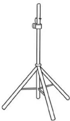
USAGE ON STAND
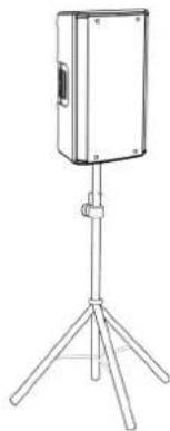
1 OPERA speaker can be installed on a tripod stand, coming as standard option with a 35 mm diameter pole. The maximum allowed height between the speaker base and the floor is 160 cm.

WARNING!
- Use a suitably sized stand with the central leg pointing forward to provide appropriate stability.
natural_image
Line drawing of a portable electronic device mounted on a tripod stand (no text or symbols)USAGE ON SUBWOOFER
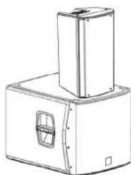
Through the installation with the DS-2S accessory, it is possible to use 1 OPERA directly on subwoofer provided with M20 hole.
natural_image
Line drawing of a mechanical device with a top component and a side panel (no text or symbols)INSTALLATION ON SUBWOOFER WITH POLE
It is possible to use only one speaker mounted on a 35 mm diameter pole. The maximum allowed height between the speaker base and the floor is 160 cm. In case of use of DVA S08DP or SUB28D an additional mechanical fastening or a belt fastening is required to correctly fix the installation.
natural_image
Line drawing of a mechanical device with a vertical support and base housing (no text or symbols)In some cases the OPERA series speakers can be used as monitors for small live contests. In this case, lay them horizontally on the tilted side. Be reminded of the sound coverage features reported in the relevant section. Use the suitable DSP settings as indicated in the "DSP preset" table in wedge mode (W1, W2, or FLAT).
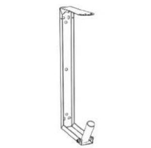
WALL-MOUNTING WITH BRACKETS
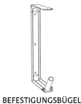
The OPERA models can be wall-mounted in vertical or horizontal position through the WB-OP10, WB-OP12, WB-OP15 accessory, to be used with OPERA10, OPERA12, OPERA15, respectively.
For further details refer to the instructions relevant to this accessory.
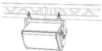
INSTALLATION ON TRUSS WITH BRACKETS AND ALISCAFF COUPLERS
The OPERA models can be installed on a truss in vertical or horizontal position, through the WB-OP10, WB-OP12, WB-OP15 accessory, to be used with OPERA10, OPERA12, OPERA15, respectively. This accessory allows the use of aliscaff couplers (not included) for this special configuration.
For further details refer to the instructions relevant to this accessory.
natural_image
Line drawing of a mechanical device with support structures above a truss structure (no text or symbols)INSTALLATION WITH EYEBOLTS
Is it possible to install the speaker using eyebolts. Positioning is represented in the opposite figure, in which the rear eyebolt allows to adjust the final angle (MAX 45°).
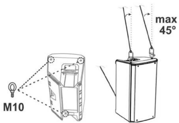
text_image
M10 max 45°The following optional accessories are available to complete the series:
- SSB2
• Wall bracket OP-WB10, OP-WB12, OP-WB15, for OPERA10, OPERA12, OPERA15, respectively
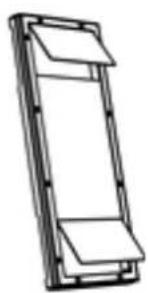
• Rain Cover RC-M1, valid for all models
natural_image
Line drawing of a tripod-mounted scientific instrument with a stand (no text or symbols)SSB2

natural_image
Line drawing of a tripod-mounted scientific instrument with adjustable arms (no text or symbols)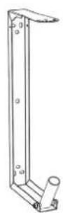
BRACKETS
natural_image
Simple line drawing of a rectangular frame with two horizontal panels and a top panel (no text or symbols)RAIN COVER

WARNING!
- Never suspend the speaker from the handles!
Please read the corresponding manuals for more details.
The speaker will not turn on:
- Check that power supply is present upstream of the installation.
- Ensure that the power supply cable with VDE connector is properly plugged in.
The speaker turns on but produces no sound:
- Check that the input connections of the audio signal (CH1 and/or CH2) are carried out correctly.
- Check the cables for damage.
- Ensure that the mixer or audio source is on and an output signal is present.
- Check that the input levels (CH1 and/or CH2) are appropriate.
Speaker sound is distorted or not sufficient:
- Adjust the first source volume, then set the input (CH1 and/or CH2) gain to an adequate level. Check the cables for damage and replace them as required (a damaged cable may lead to signal loss or alteration).
- Check that the input selection settings (CH1 -> Mic/Line, CH2 -> Line/Instr) are correct with respect to the source
- Check that the "DSP preset" settings are suitable for the use selected.
A background hum can be heard:
- Disconnect all connected devices and turn power supply off.
- Check that the Ground Lift switch is correctly set.
- Check the connection cables for damage.
- Connect cables again and turn speaker on.
| Type: | 2-way active speaker |
ACOUSTICAL SPECIFICATIONS
| Frequency response [-10dB]: | 58 - 20k Hz (OPERA10) / 52 - 20k Hz (OPERA12) / 50 - 20k Hz (OPERA15) |
| Frequency response [-3dB]: | 70 - 19.6k Hz (OPERA10) / 67 - 19.6k Hz (OPERA12) / 56 - 19.6k Hz (OPERA15) |
| Max SPL: | 128 dB (OPERA10) / 129 dB (OPERA12) / 130 dB (OPERA15) |
| HF voice coil: | 1.4” |
| HF compression driver (output): | 1” |
| LF: | 10” (OPERA10) / 12” (OPERA12) / 15” (OPERA15) |
| LF Voice coil: | 2” |
| Crossover frequency (24 dB/oct): | 2000 Hz |
| Directivity: | Asymmetrical vertical - Differentiated horizontal |
| Coverage (HxV): | 85°- 120° x 80° (+25°/-60°) |
AMPLIFIER
| Type: | AMP SMPS |
| Amplification class: | Class D |
| Power supply: | 1 x VDE |
| RMS amplifier power: | 600 W |
| Peak power: | 1200 W |
PROCESSOR
| Internal controller: | 56-bit DSP |
| A/D D/A converter: | 24 bit/48 kHz |
| Limiter: | Peak, RMS, Thermal |
INPUTS
| Inputs: | 1x balanced/unbalanced Combo (XLR/Jack) |
| Outputs: | 1x XLR link OUT |
USER INTERFACE
| Controls: Level control, ground lift switch, 8-position DSP preset rotary switch |
POWER SUPPLY SPECIFICATIONS
| Draw at 1/8 of full power in average use conditions (*): | 0,92 A (230 V) - 1,65 A (115 V) |
| Draw at 1/3 of full power in maximum use conditions (**): | 2,25 A (230 V) - 4,05 A (115 V) |
| Draw with speaker turned on without signal (idle): : | 14 W |
| Inrush current: | 14,07 A |
* INSTALLER NOTES: The values refer to 1/8 of full power, in average operating conditions (music program with infrequent or no clipping). It is recommended to consider them the minimum sizing values for any type of configuration.
** INSTALLER NOTES: The values refer to 1/3 of full power, in heavy operating conditions (music program with frequent clipping or activation of the limiter). We recommend sizing according to these values in case of professional installations and tours.
Product features, specifications and appearance are subject to changes without prior notice. dBTechnologies reserves the right to make changes or improvements in design or manufacture without any obligation to incorporate such changes or improvements in products manufactured before their introduction.

text_image
A BA.E.B. Industriale Srl
Via Brodolini, 8
Audiosignals).... 44
INSTALLATION AUF EINEM SUBWOOFER 45
INSTALLATION AUF EINEM SUBWOOFER MIT 45
PFOSTEN 45
WEDGE INSTALLATION (MONITORING) 46
WANDINSTALLATION MIT BEFESTIGUNGSBÜGELN 46
INSTALLATION AN TRAVERSEN MIT BÜGELN UND 46
ALISCAFF-KUPPLUNGEN 46
INSTALLATION MIT EYEBOLT-HAKEN 46
4. ZUBEHÖR 47
5. PROBLEMABHILFE 48
INSTALLATION AUF EINEM SUBWOOFER
INSTALLATION AUF EINEM SUBWOOFER MIT PFOSTEN
natural_image
Line drawing of a portable electronic device mounted on a tripod stand (no text or symbols)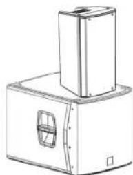
natural_image
Technical line drawing of a mechanical device with a square base and rectangular housing (no text or symbols)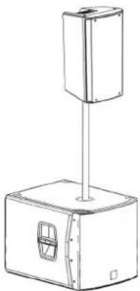
natural_image
Line drawing of a mechanical device with a vertical support and base housing (no text or symbols)OPERA10 OPERA12 OPERA 15 COD. 420120247 REV. 1.1
WEDGE INSTALLATION (MONITORING)
natural_image
Line drawing of a mechanical device with a triangular frame above it (no text or symbols)natural_image
Two identical line drawings of a tripod-mounted stand with metal legs and support brackets (no text or symbols)SSB2
natural_image
Technical line drawing of a vertical metal bracket with mounting holes and a small protrusion, labeled 'BEFESTIGUNGSBÜGEL' below (no other text or symbols)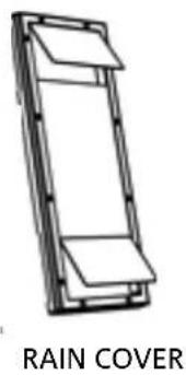
text_image
RAIN COVER
ACHTUNG!
DONNÉES ACOUSTIQUES 65
AMPLIFICATEUR 65
PROCESSEUR 66
INTERFACE UTILISATEUR 66
ENTRÉES 66
SPÉCIFICATIONS D'ALIMENTATION (ABSORPTION / INSTALLATION).... 66
DIMENSIONS 67
OPERA10 OPERA12 OPERA 15 Code 420120247 RÉV. 1.1
1. GÉNÉRALITÉS
BIENVENUS!
natural_image
Line drawing of a portable electronic device mounted on a tripod stand (no text or symbols)INSTALLATION SUR SUBWOOFER
natural_image
Technical line drawing of a mechanical device with a rectangular base and a cylindrical top component (no text or symbols)INSTALLATION SUR SUBWOOFER AVEC POTEAU
natural_image
Technical line drawing of a mechanical device with a vertical support and base housing (no text or symbols)OPERA10 OPERA12 OPERA 15 Code 420120247 RÉV. 1.1
INSTALLATION WEDGE (MONITORING)
natural_image
Line drawing of a mechanical device with mounting brackets and a triangular frame above (no text or symbols)INSTALLATION AVEC EYEBOLTS
natural_image
Two identical line drawings of a tripod-mounted scientific instrument with adjustable arms (no text or symbols)SSB2
ÉTRIERS
natural_image
Simple line drawing of a rectangular frame with two horizontal panels, no text or symbols present.HOUSSE ANTI-PLUIE

ATTENTION!
text_image
Line Mic Audio Input Sens. MIXER / LÍNEA 5 Balanced Input Line Mic Audio Input Sens. Diff Diff Diff DSP Preset Main Limitar Signal / ON Ground 1 Balanced Input Line Instr Balanced Out Output Out Resulting Selector Ots Link Mix Out 2 DSP Preset 3 Club Vocal Bass Reduction Playback Bass Boost W11 W22 Wedge Vocal Wedge Playback FLAT 3 OPERA dBTechologies DESIGNED & DEVELOPED IN ITALY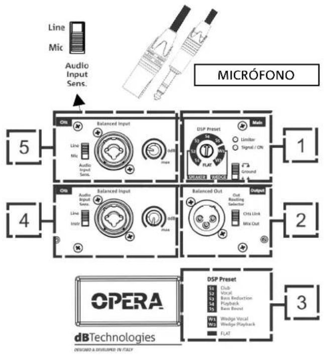
flowchart
graph TD
    A["Line Mic Audio Input Sens."] --> B["MICRÓFONO"]
    B --> C["5"]
    B --> D["1"]
    B --> E["2"]
    B --> F["3"]
    B --> G["4"]
    B --> H["5"]
    B --> I["6"]
    B --> J["7"]
    B --> K["8"]
    B --> L["9"]
    B --> M["10"]
    B --> N["11"]
    B --> O["12"]
    B --> P["13"]
    B --> Q["14"]
    B --> R["15"]
    B --> S["16"]
    B --> T["17"]
    B --> U["18"]
    B --> V["19"]
    B --> W["20"]
    B --> X["21"]
    B --> Y["22"]
    B --> Z["23"]
    B --> AA["24"]
    B --> AB["25"]
    B --> AC["26"]
    B --> AD["27"]
    B --> AE["28"]
    B --> AF["29"]
    B --> AG["30"]
    B --> AH["31"]
    B --> AI["32"]
    B --> AJ["33"]
    B --> AK["34"]
    B --> AL["35"]
    B --> AM["36"]
    B --> AN["37"]
    B --> AO["38"]
    B --> AP["39"]
    B --> AQ["40"]
    B --> AR["41"]
    B --> AS["42"]
    B --> AT["43"]
    B --> AU["44"]
    B --> AV["45"]
    B --> AW["46"]
    B --> AX["47"]
    B --> AY["48"]
    B --> AZ["49"]
    B --> BA["50"]
OPERA10 OPERA12 OPERA 15 Cód. 420120247 REV. 1.1
natural_image
Line drawing of a portable electronic device mounted on a tripod stand (no text or symbols)natural_image
Line drawing of a mechanical device with a rectangular base and a square opening, featuring a small inset view (no text or symbols)natural_image
Technical line drawing of a mechanical device with a vertical support and rectangular base (no text or symbols)OPERA10 OPERA12 OPERA 15 Cód. 420120247 REV. 1.1
natural_image
Line drawing of a mechanical device mounted on a truss structure (no text or symbols)natural_image
Line drawing of two identical tripod-mounted scientific instruments or support poles (no text or symbols)SSB2
natural_image
Technical line drawing of a vertical metal frame with mounting holes and a cylindrical base (no text or symbols)SOPORTES
natural_image
Simple line drawing of a rectangular frame with two horizontal panels, no text or symbols present.RAIN COVER

¡ATENCIÓN!