TB 60 - Measuring equipment Testboy - Free user manual and instructions
Find the device manual for free TB 60 Testboy in PDF.
| Product type | Automotive voltage tester |
| Brand | Testboy |
| Model | TB 60 |
| Dimensions | 260 x 53 x 40 mm |
| Weight | 430 g (including test cables) |
| Power supply | 12 - 24 V DC (vehicle battery) |
| Voltage measurement range | 1 - 60 V |
| Display | LCD screen + 2 LEDs (positive/negative) |
| Length of test cables | Approximately 6 m |
| Operating modes | Voltage test, polarity test, continuity test, component test, positive/negative activation, trailer light test, ignition pulse detection, frequency measurement, voltage spike detection |
| Protection | Short-circuit protection with resettable fuse |
| Intended use | By qualified electricians for automotive 12/24 V systems |
| Operating temperature | Above 5 °C (otherwise risk of malfunction) |
| Cleaning | Damp cloth with mild detergent; do not use solvents |
| Maintenance | No special maintenance if used properly |
| Certification | CE, compliant with applicable directives |
| Warranty | Warranty void if instructions not followed or unauthorized modification |
Frequently Asked Questions - TB 60 Testboy
User questions about TB 60 Testboy
0 question about this device. Answer the ones you know or ask your own.
Ask a new question about this device
Download the instructions for your Measuring equipment in PDF format for free! Find your manual TB 60 - Testboy and take your electronic device back in hand. On this page are published all the documents necessary for the use of your device. TB 60 by Testboy.
USER MANUAL TB 60 Testboy
natural_image
Illustration of a handheld electronic device connected to two test probes (no text or symbols visible)Testboy® TB 60
Version 1.4

Testboy ^® TB 60 3
Bedienungsanleitung

Testboy® TB 60 13
Operating Manual

Testboy® TB 60 23
text_image
Labeled diagram of a handheld electronic device with numbered parts for identificationFunktion
text_image
Diagram showing two identical electrical testing setups with digital displays, connected to a battery and cable, each connected to a clamp.Komponentenprüfung
text_image
Electrical circuit diagram showing connections between a battery, switch, measurement device, and industrial equipment with labeled components.natural_image
Illustration of a handheld electronic device with a probe inserted into a pipe (no text or symbols visible)natural_image
Illustration of a handheld electronic device with a multi-wire connector and terminal leads (no text or symbols visible)natural_image
Illustration of a digital voltage tester with a probe inserted into a terminal block (no text or symbols visible)4 Takt (1, 2, 3, 4, 5, 6, 8, 12 Zylinder)
$$ n = 6 0 \times f \times 1 / P R $$
| PR | 4-Takt | 2-Takt |
| 1/2 | 1 Zylinder | |
| 1 | 2 Zylinder | 1 Zylinder |
| 3/2 | 3 Zylinder | |
| 2 | 4 Zylinder | 2 Zylinder |
| 5/2 | 5 Zylinder | |
| 3 | 6 Zylinder | 3 Zylinder |
| 4 | 8 Zylinder | 4 Zylinder |
| 6 | 12 Zylinder |
Peakerkennung
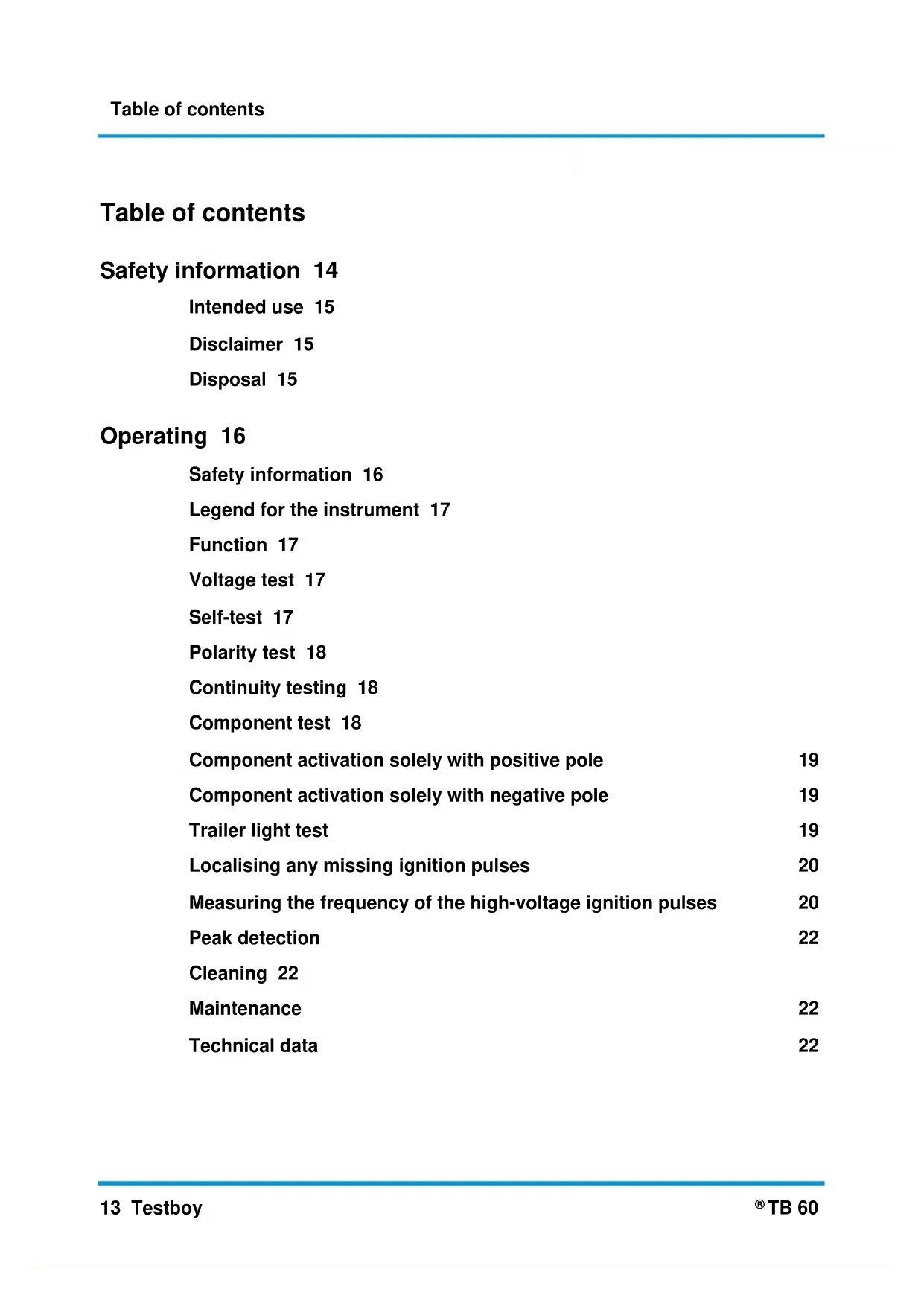
Legend for the instrument 17
Function 17
Voltage test 17
Self-test 17
Polarity test 18
Continuity testing 18
Component test 18
Component activation solely with positive pole 19
Component activation solely with negative pole 19
Trailer light test 19
Localising any missing ignition pulses 20
Measuring the frequency of the high-voltage ignition pulses 20
Peak detection 22
Cleaning 22
Maintenance 22
Technical data 22
Safety information
 | WARNINGRead this manual carefully before using the instrument. Failure to use the instrument in accordance with the manufacturer's specifications can affect the protection which it provides. |
 | WARNINGSources of danger include e.g. mechanical parts, which can cause serious injuries. Objects are also at risk (e.g. damage to the instrument). |
 | WARNINGAn electric shock can result in death or serious injury and jeopardise the function of objects (e.g. damage to the instrument). |
 | WARNINGUnauthorised modification and/or changes to the instrument are not permitted for reasons of safety and approval (CE). In order to ensure safe and reliable operation of the instrument, you must always comply with the safety information, warnings and the information contained in the section "Intended use". |
 | WARNINGObserve the following information before using the instrument:Avoid operating the instrument near to electric welding equipment, induction heaters or other electromagnetic fields.To stabilise the instrument after abrupt changes in temperature, the instrument must be allowed to adjust to the new ambient temperature for approx. 30 minutes before using it.Temperatures below 5 °C can impair the readiness of the voltage tester. Please provide sufficient power supply by using suitable batteries which are also specified for the appointed temperature range!Do not expose the instrument to high temperatures for a long period of time.Avoid dusty and humid environments.The voltage tester and accessories are not toys and must be kept out of the reach of children!When working in commercial facilities, comply at all times with the accident prevention regulations for electrical systems and equipment as established by the employer's liability insurance association. |
 | Please observe the five safety rules:1 Disconnect2 Secure the instrument against reactivation3 Ensure isolation from the power supply (check that there is no voltage on both poles)4 Earth and short-circuit5 Cover adjacent live parts |
 | WARNINGCompared to the reference value of 100 kΩ, a voltage tester with relatively low impedance does not indicate all interference voltages with an original value above the ELV. Given contact with the parts of the system to be tested, discharge can mean that the voltage tester temporarily diminishes the interference voltages to a level under the ELV. Removing the voltage tester returns the interference voltage to its original value.Compared to the reference value of 100 kΩ, a voltage tester with relatively high internal impedance at the existing interference voltage cannot clearly indicate "operating voltage not present".If the indication "Voltage present" does not appear, we strongly recommend that you insert the earthing device before starting the work.If the indication "Voltage present" appears for a part that is considered to be separate from the system, we strongly recommend that you take additional action (e.g.: use a suitable voltage tester, visually check the sepa- |
rating point in the electrical network etc.), verify and determine the condition of the “Operating voltage not present” of the part of the system to be tested and determine that the voltage indicated by the voltage tester is an interference voltage.
Intended use
Only intended for use by qualified electricians and specialized personnel.
The instrument is only intended for the applications described in the operating instructions, such as AC, DC and continuity checks, phase and rotating field test. Any other usage is forbidden and can result in accidents or destruction of the instrument. Any such misapplication will result in the immediate expiry of all guarantee and warranty claims on the part of the operator against the manufacturer.
All users of this test instrument should be in possession of the appropriate training and be familiar with the dangers associated with performing a voltage test which occur in an industrial environment, with the necessary safety precautions and the procedure for checking the correct function of the instrument before and after each use.

We shall not accept any liability for damage to property or injury to persons resulting from improper handling or non-compliance with the safety information. In such cases, any warranty claim becomes invalid. An exclamation mark in a triangle indicates safety information in the operating manual. Read the entire manual before commissioning. This instrument is CE-approved and thus fulfils the required directives.
We reserve the right to change specifications without prior notice © 2020 Testboy GmbH, Germany.
Disclaimer

The warranty claim will be voided in cases of damage caused by failure to comply with the specifications of the manual! We shall not accept any liability for the resulting damage!
Testboy does not accept responsibility for damage resulting from:
Failure to observe the instructions
Changes to the product which have not been approved by Testboy
Spare parts which have not been manufactured by Testboy
The consumption of alcohol, narcotics and medicine.
Correctness of the operating manual
This operating manual has been compiled with considerable care and attention. No guarantee is given that the data, figures and drawings are complete or correct. Subject to changes, printing mistakes and errors.
Disposal
Dear Testboy customer, purchasing our product gives you the option of returning the instrument to suitable collection points for waste electrical equipment at the end of its lifespan.

The WEEE directive regulates the return and recycling of electrical appliances. Manufacturers of electrical appliances are obliged to take back and recycle all electrical appliances free of charge. Electrical appliances may no longer be disposed of through conventional waste disposal channels. Electrical appliances must be recycled and disposed of separately. All equipment subject to this directive is marked with this logo.
Certificate of quality
All quality-related activities and processes performed by Testboy GmbH are subject to continual monitoring within the framework of a Quality Management System. Testboy GmbH confirms that the testing equipment and instruments used during the calibration process are subject to a continual monitoring process.
Declaration of conformity
The product conforms to the most recent directives. For further information, go to www.testboy.de
Operating
Thank you very much for purchasing the Testboy® TB 60, an automotive voltage tester with LCD display. Voltage (1 V to 60 V), polarity and continuity tests can be carried out without having to remove individual components from the battery and re-attach them. Frequency measurements of the ignition pulses can be carried out. It can also be calculated whether the engine speeds shown are correct.
Safety information
You have chosen an instrument providing a high degree of safety. To ensure safe and correct application, it is necessary to fully read this operating manual before using the instrument for the first time.
For test and safety purposes, the instrument has a short-circuit protective device which allows the earthing connection to be examined without any voltage drop test. The short-circuit system has a restorable fuse thus preventing the technician from destroying the fuses during the test.
The test leads are long enough for the whole system to be tested without the need to have to regularly find an earthing point.
The presence of voltage could result in a spark flying given contact with the earthing. That is why work should never be undertaken with a 110/220 mains voltage. The instrument is solely designed for a 12-24 volt supply.

On the circuit-breaker being triggered, do not touch the measurement probe or the measurement probe adapter. The measurement probe and adapter become vey hot when the circuit-breaker is triggered!

When applying current to components, only press the switch before the measurement probe touches the component. In this case the arc forms between the probe and the component rather than the switch. This may extend the service life of the switch.
The following safety precautions apply:
Make sure that the test line and instrument are fully serviceable. Check the instrument on a known source of voltage.
If the display fails to indicate one or more functions in the process, do not continue to use the instrument. It must be checked by a specialist.
Only hold the instrument on the handles below the mechanical mark; avoid contact with the test probes!
The instrument must not be operated in a humid environment!
Always keep the instrument dry and clean. Only use a moist cloth to clean the housing.
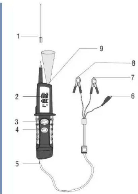
Legend for the instrument
- Test probe (extension)
- LCD display
- Mode select button
- Polarity switch
- Test lead
- Earth lead
- Black lead for power supply (-)
- Red lead for power supply (+)
- Light
text_image
Labeled diagram of a handheld electronic device with numbered parts for identificationFunction
To switch on the instrument, connect the red test lead with the plus pole of the vehicle battery and the black test lead to the minus pole of the vehicle battery. If necessary, connect the earth lead with a corresponding measuring point.
The instrument has 4 modi which can be run through by pressing the "Mode select" key. For this, press the button for approximately one second. The instrument always starts in the first mode (voltage tester).
Attaching or detaching the test probe adapter makes it easier to undertake testing at plugs or connectors.
Voltage test

Do not under any circumstances change the polarity in this mode!
When placing the test probes on a DC voltage within the rated voltage range, the voltage is indicated in volts on the display. If the positive pole is touched, the red LED lights up. If the negative pole is touched, the green LED lights up.
Self-test
To see if the instrument functions properly, the following self-test can be carried out:
In this connection, the test probe must not be touched!
- The red LED should light up when the polarity change switch is pressed forward and with the test probe not touching anywhere
- The green LED should light up when the polarity change switch is pressed to the rear and with the test probe not touching anywhere
If these functions do not work, then the instrument should be sent in for examination by specialist personnel!
17 Testboy
Polarity test
The red LED lights up when the test probes rest on a positive contact within the rated voltage range. The green LED lights up on the test probe coming into contact with a negative pole. The lead is considered to be interrupted should no LED light up in one of the above instances.
Continuity testing

The earth lead has to be used for this test!
By using the test probe, which supports the earth lead, you can test the conductivity between wires or components which have been disconnected from the vehicle's electrical system. The green LED should light up when current flows between wires.
text_image
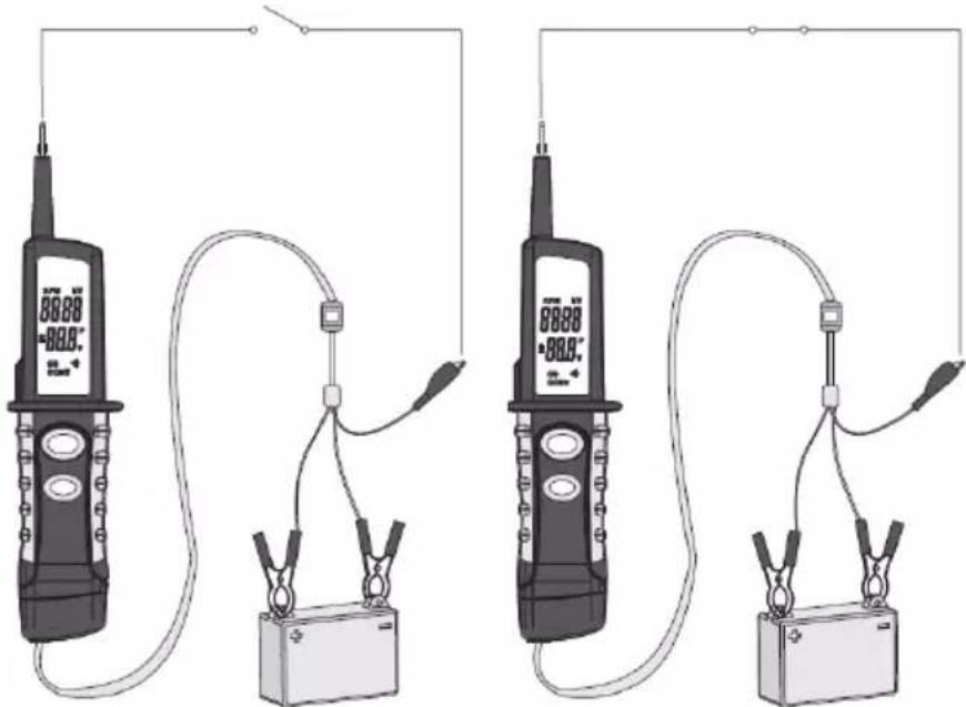
Diagram showing two identical electrical testing devices connected to a battery, each displaying a digital display with temperature reading.Component test
By deploying the measurement probe and earth lead, the user can activate the components to be tested without attaching them to the vehicle's electrical system. Light, fan and fuel pumps, for instance, can be tested with this function. For this, please follow the following procedure:
- Connect the earth lead to the negative pole of the component.
- Connect the measurement probe to the positive pole of the component. The fact of the green LED lighting up means that the component is conductive.
-
When the green LED lights up, press the polarity switch forward and then release it immediately. You can continue with the test when the LED changes from green to red. However, the fact of the green LED going out and the red LED not lighting up or the circuit breaker being triggered means that the tester is overloaded. This could be due to the following:
-
The component either has a short-circuit or was attached with the polarity reversed.
- The component is a high-efficiency component.
The circuit-breaker regenerates itself within 60 seconds from being triggered.
Component activation solely with positive pole
Components being tested by the user can be supplied through the TB 60 with exclusively positive voltage.
- Connect the measurement probe to the positive pole of the component. The fact of the green LED lighting up means that the component is conductive.
- When the green LED lights up, press the polarity switch forwards and then release it immediately. However, the fact of the green LED going out and the red LED not lighting up or the circuit breaker being triggered means that the tester is overloaded. This could be due to the following:
The component either has a short-circuit or was attached with the polarity reversed.
- The component is a high-efficiency component.
The circuit-breaker regenerates itself within 60 seconds from being triggered.
Component activation solely with negative pole
Components being tested by the user can be supplied through the TB 60 with exclusively negative voltage.
- Connect the measurement probe to the negative pole of the component. The fact of the red LED lighting up means that the component is conductive.
- When the red LED lights up, press the polarity switch to the rear and then release it immediately. However, the fact of the red LED going out and the green LED not lighting up or the circuit breaker being triggered means that the tester is overloaded. This could be due to the following:
- The component either has a short-circuit or was attached with the polarity reversed.
- The component is a high-efficiency component.
The circuit-breaker regenerates itself within 60 seconds from being triggered.
Trailer light test
The following procedure must be followed when examining the light system of a trailer:
- Connect the earth lead to the earthing of the trailer.
- By using the measurement probe, a connection can now be set up to the lighting system at the trailer plug connector. The light can be tested by now pressing the polarity change-over switch forwards.
- The green LED lights up when the probe comes into contact with the negative pole.
natural_image
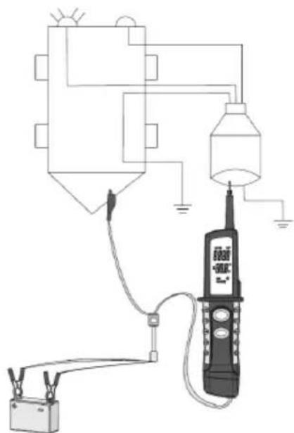
Pure electrical circuit lines without any symbolsLocalising any missing ignition pulses
Select the "kV" mode with the Mode select button to check which ignition pulse is absent. By positioning the test probe of the tester next to an ignition cable (NO direct contact!), a capacitive coupling enables the tester to record the high-voltage ignition pulses and simultaneously display a voltage value. Any missing cylinder can be localized by monitoring each ignition cable in this way.
Measuring the frequency of the high-voltage ignition pulses
Select the "Hc" mode with the Mode select button to change to the frequency mode. The tester can measure the frequency of the ignition pulses. By positioning the test probe next to an ignition wire (NO direct testing), a capacitive coupling enables the tester to record the ignition pulses and simultaneously display a frequency value.
Measuring technique 1: for each cylinder at the ignition cable
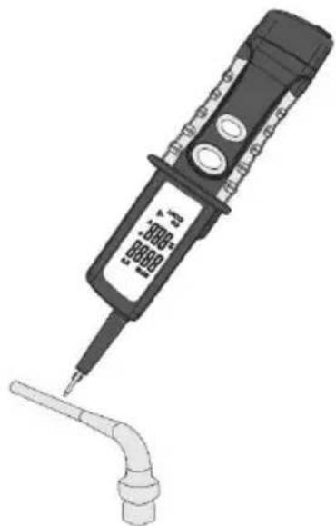
natural_image
Illustration of a digital voltage tester with probe tip and terminal connector (no text or symbols)Measuring technique 2: ignition cable section of several cylinders
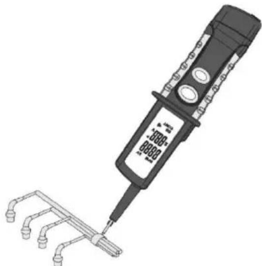
natural_image
Illustration of a handheld electronic device with a terminal connector and three tubes, no visible text or symbols.Measuring technique 3: at the ignition distributor / ignition coil
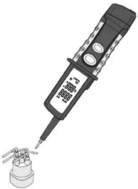
natural_image
Illustration of a digital soldering iron with a base, showing its tip and terminal (no text or symbols present)High-voltage cable between distributor and ignition coil. Move the recording head - as shown - to a point near the high-voltage cable connecting the distributor to the ignition coil or to where all high-voltage cables of the cylinders are found together.
Multi-cylinder petrol engines without distributor. Move the detecting head near to a point where the high-voltage wire of each cylinder is bundled. No measurement is possible if not all the high-voltage wires are bundled. This is because of the differences in how far apart the recording head is from each high-voltage wire.
Specifications
Engine types: Petrol engines
2 stroke (1 - 4 cylinders)
4 stroke (1, 2, 3, 4, 5, 6, 8, 12 cylinders)
Detection technique: detecting ignition spark noise
Item to be detected: high-voltage cable or ignition cable
Calculation of the engine speed
The engine speed can be calculated on the basis of the measured frequency. The calculation formula is as follows:
$$ n = 6 0 \times f \times 1 / P R $$
“n” stands for the engine speed
“P” stands for the frequency of the high-voltage ignition pulse.
"PR" stands for the ratio coefficients between "f" and "n".
The PR value can be ascertained on the basis of the following engine table:
| PR | 4-stroke | 2-stroke |
| 1/2 | 1 cylinder | |
| 1 | 2 cylinders | 1 cylinder |
| 3/2 | 3 cylinders | |
| 2 | 4 cylinders | 2 cylinders |
| 5/2 | 5 cylinders | |
| 3 | 6 cylinders | 3 cylinders |
| 4 | 8 cylinders | 4 cylinders |
| 6 | 12 cylinders |
Peak detection
The voltage peak can be checked in this mode. Use the mode select button to change to the “+/-” mode and set the maximum permitted voltage by pressing the mode select button. The possible settings are 0.5 V, 1 V, 2 V, 5 V, 10 V and 48 V. With the required target value set, apply electrical current to the corresponding lead with the test probe. The instrument emits an acoustic signal when the set value is exceeded. A change is then made to the next higher setting and no further sounds should come from the instrument.

Example: A 12 V maximum is to be applied to the lead. The instrument is set to 10 V and checked. As the 10 V have been exceeded, a sound is heard from the instrument. The next higher range is now chosen (48 V) and the signal is silenced.
Cleaning
Use a damp cloth and mild household detergent to clean the instrument should it become soiled through daily use. Never use aggressive cleaning agents or solvents to clean the instrument.

To avoid electric shocks, do not allow moisture to penetrate the housing.
Maintenance
The instrument does not require special maintenance when used as specified in this operating manual.
Technical data
| Display | 2 LEDs for voltage (positive and negative), LC display |
| Voltage supply | 12 - 24 V DC (own-vehicle battery) |
| Test leads length | approx. 6 m |
| Measurement range | 1 - 60 V |
| Dimensions | 260 x 53 x 40 mm |
| Weight | 430 g incl. test leads |
Table des matières
text_image
Labeled diagram of a handheld electronic device with numbered parts for identificationFonction
natural_image
Two identical electrical testing devices connected to a battery, each displaying a digital display and cable (no text or symbols visible)natural_image
Pure electrical circuit lines without any symbolsnatural_image
Illustration of a handheld electrical probe with a pipe fitting (no text or symbols visible)natural_image
Illustration of a handheld electronic device with a separate pipe fitting (no text or symbols visible)natural_image
Illustration of a soldering iron with a digital display and terminal connector (no text or symbols)$$ n = 6 0 \times f \times 1 / P R $$
text_image
Labeled diagram of a handheld electronic device with numbered parts for identificationFunción
text_image
Diagram showing two identical electrical testing setups with digital meters, connected to a battery and cable, each connected to a switch.natural_image
Pure electrical circuit lines without any symbolsnatural_image
Illustration of a handheld electrical probe with a terminal connector and a pipe fitting (no text or symbols visible)natural_image
Illustration of a handheld electronic device with a terminal connector and three leads, showing no visible text or symbols.natural_image
Illustration of a soldering iron with a digital display and terminal connector (no text or symbols)$$ n = 6 0 \times f \times 1 / P R $$
text_image
Labeled diagram of a handheld electronic device with numbered parts for identificationFunzionamento
text_image
Diagram showing two identical electrical testing setups with digital displays, connected to a battery and cable, each connected to a clamp.text_image
Electrical circuit diagram showing connections between a device, battery, and control panel with labeled componentsnatural_image
Illustration of a handheld electrical probe with a terminal plug, no visible text or symbolsnatural_image
Illustration of a handheld electronic device with three leads and a separate pipe bundle (no text or symbols visible)natural_image
Illustration of a soldering iron with a digital display and terminal connector (no text or symbols)$$ n = 6 0 \times f \times 1 / P R $$
text_image
Labeled diagram of a handheld electronic device with numbered parts for identificationWerking
text_image
Diagram showing two identical electrical testing setups with digital displays, connected to a battery and cable, each connected to a clamp.Controle van componenten
text_image
Electrical circuit diagram showing connections between a device, battery, and control panel with labeled componentsnatural_image
Illustration of a handheld electrical probe with a terminal plug, no visible text or symbolsnatural_image
Illustration of a handheld electrical testing device with three leads and a terminal connector (no text or symbols visible)natural_image
Illustration of a digital soldering iron with a base, showing its tip and terminal (no text or symbols present)$$ n = 6 0 x f x 1 / P R $$
text_image
Testboy® GmbH, Germany Stands For Quality Since 1953Testboy GmbH Tel: +49 4441 89112-10
Germany info@testboy.de