GM70 - Measuring equipment VOLTCRAFT - Free user manual and instructions
Find the device manual for free GM70 VOLTCRAFT in PDF.

User questions about GM70 VOLTCRAFT
0 question about this device. Answer the ones you know or ask your own.
Ask a new question about this device
Download the instructions for your Measuring equipment in PDF format for free! Find your manual GM70 - VOLTCRAFT and take your electronic device back in hand. On this page are published all the documents necessary for the use of your device. GM70 by VOLTCRAFT.
USER MANUAL GM70 VOLTCRAFT
Item No. 1665723 Page 18 - 33
F Notice d'emploi
- Introduction 19
- Explanation of symbols 19
- Intended use 20
- Delivery content 20
- Features and functions 21
- Safety information 21
a) General information 21
b) Persons and product 22
c) Battery 22
- Operating elements 23
a) Measuring device 23
b) Display symbols. 24
c)Button functions 24
- Setup 24
a) Installing/replacing the battery 24
b) Operation with a power adapter 25
c) Connecting the measuring sensor. 25
d) Positioning the measuring sensor 25
e) Setting up the measuring device 25
- Operation 26
a) Switch the device on and off. 26
b) Advanced settings 26
c) Selecting the unit of measurement 26
d) Calibration setting 27
- Carrying out a measurement 27
a) Zero adjustment (relative measurement). 27
b) HOLD function 28
c) Measuring DC magnetic fields (static) 28
d) Measuring AC magnetic fields (changing) 29
(e)REC measured value memory 30
f) RS232 port 30
g)Restoring the default settings 31
- Troubleshooting 32
- Care and cleaning 32
- Disposal 32
a) Product 32
b) Battery information 32
- Technical specifications 33
1. Introduction
Dear customer,
Thank you for purchasing this product.
This product complies with statutory, national and European regulations.
To ensure that the product remains in this state and to guarantee safe operation, always follow the instructions in these operating instructions.

These operating instructions are part of this product. They contain important information on setting up and using the product. Do not give this product to a third party without the operating instructions. Therefore, retain these operating instructions for reference!
If there are any technical questions, please contact:
International: www.conrad.com/contact
United Kingdom: www.conrad-electronic.co.uk/contact
2. Explanation of symbols

The symbol with the lightning in a triangle indicates that there is a risk to your health, e.g. due to an electric shock.

The symbol with an exclamation mark in a triangle is used to highlight important information in these operating instructions. Always read this information carefully.

The arrow symbol indicates special information and tips on how to use the product.
3. Intended use
The magnetic field analysis device is intended for detecting magnetic DC and AC fields. It is a highly sensitive magnetic field measuring device for a wide range of applications in industry, development, electronics and mechanics. It is suitable for checking the function of energised coils, e.g. in relays, in solenoid valves, etc. Since it is a non-contact magnetic field analysis device, in most cases you will not need to open the housing to facilitate testing.
The sensor enables the measurement of DC and AC magnetic fields in the range 300 to 3000mT or 150 to 1500mT (millitesla). When measuring DC magnetic fields, the polarity of the magnetic field (north/south) is displayed. The high sensitivity of the sensor enables measurement of magnetic fields for reference purposes. An RS232 interface allows forwarding and processing of measurement data by means of an appropriate (optional) data cable.
A 9 V block battery is required for operation (included). Operation with a power adapter is also possible. The power adapter is not included with the product.
This product is intended for indoor use only. Do not use it outdoors. Contact with moisture (e.g. in a bathroom) must be avoided under all circumstances.
For safety and approval purposes, do not rebuild and/or modify this product. Using the product for purposes other than those described above may damage the product. In addition, improper use can cause hazards such as a short circuit or fire. Read the operating instructions carefully and store them in a safe place. Only make this product available to third parties together with its operating instructions.
All company and product names included herein are trademarks of their respective owners. All rights reserved.
4. Delivery content
- 1x Magnetic field analyser
1xProbe - 1x9Vbattery
- 1x CA-06 storage case
- Operating instructions
Up-to-date operating instructions
To download the latest operating instructions, visit www.conrad.com/downloads or scan the QR code on this page. Follow the instructions on the website.

5. Features and functions
- Versatile applicable in industry, materials research and laboratories
- Separate sensor for easy operation and for remote measurement
- Robust compact housing for secure transport
- The highest possible accuracy through an integrated circuit
- Extensive functions
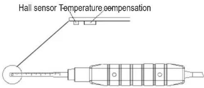
- Hall effect sensor with automatic temperature compensation
6. Safety information

Read the operating instructions and safety information carefully. If you do not follow the safety information and information on proper handling in these operating instructions, we will assume no liability for any resulting personal injury or damage to property. Such cases will invalidate the warranty/guarantee.
a) General information
- The product is not a toy. Keep it out of the reach of children and pets.
- Do not leave packaging material lying around carelessly. It may become a dangerous plaything for children.
- Protect the product from extreme temperatures, direct sunlight, strong jolts, high humidity, moisture, flammable gases, vapours and solvents.
- Never expose the product to mechanical stress.
-
If it is no longer possible to operate the product safely, stop using it and prevent unauthorised use. Safe operation can no longer be guaranteed if the product:
-
is visibly damaged,
- is no longer working properly,
- has been stored for extended periods in poor ambient conditions or
-
has been subjected to any serious transport-related stress.
-
Please handle the product carefully. Jolts, impacts or a fall even from a low height may damage the product.
- Always observe the safety and operating instructions of any other devices which are connected to the product.
- Contact an expert when in doubt about the operation, safety or connection of the product.
- Maintenance, modifications and repairs must only be carried out by a technician or a specialist repair centre.

- If you have any questions that are not answered in these operating instructions, please contact our technical customer service or other professionals.
b) Persons and product
- Never measure on bare, live wires.
- Never use the product immediately after it has been brought from a cold room into a warm one. The condensation generated may destroy the product. Allow the product to reach room temperature while off before connecting it and putting it into to use. This may take several hours.
- Working with magnetic components or remaining in a magnetic environment can lead to malfunctions of heart pacemakers.
- Always comply with the accident prevention regulations for electrical equipment when using the product in commercial facilities.
- In schools, educational facilities, hobby and DIY workshops, measuring devices must be operated under the responsible supervision of qualified personnel.
- The measuring device must not be used in areas at risk of explosion.
- Observe the safety information in each section.
c) Battery
- Always ensure that the battery is inserted in the correct polarity.
- To prevent the battery from leaking, remove it from the device if you are not going to use the product for a prolonged period. Leaking or damaged batteries may cause acid burns if they come into contact with your skin. Always use suitable protective gloves when handling damaged batteries.
- Batteries must be kept out of the reach of children. Do not leave batteries lying around, as there is a risk that children or pets may swallow them.
- Batteries must not be dismantled, short-circuited or thrown into open flames. Never charge non-rechargeable batteries. This may cause an explosion!
7. Operating elements
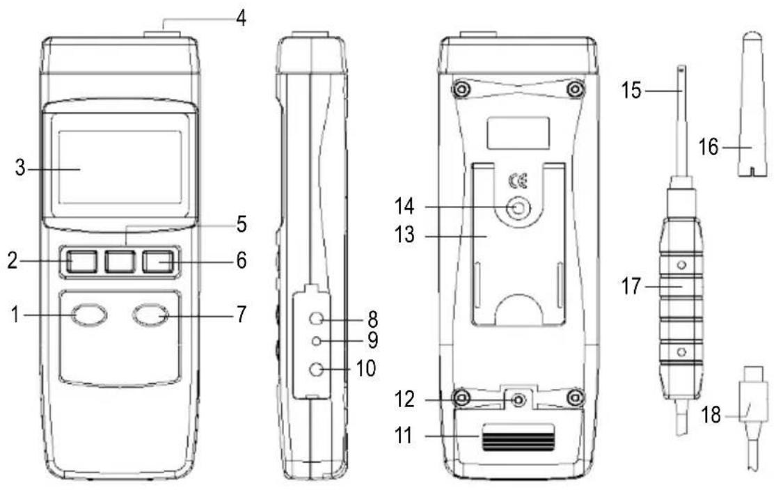
a) Measuring device
1 ZERO button
2 POWER button
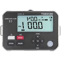
3 LC display
4 Measurement socket for external sensor
5 HOLD button
6 REC button
7 MODE - DC AC (SET) button
8 RS232 interface RS232 OUTPUT
9 RESET button
10 DC 9 V power adapter connection socket
11 Battery compartment cover
12 Battery compartment screw
13 Device stand
14 Tripod socket
15 Sensor head
16 Protective cap (for sensor head)
17 Sensor handle
18 Sensor connection plug
b) Display symbols
G Gauss, natural unit of magnetic flux density
mT Millitesla, SI unit of magnetic flux density
N Indicates a positive magnetic field (north pole with DC)
S Indicates a negative magnetic field (south pole with DC)
AC Indicates AC field mode
REC Indicates minimum/maximum value data recording
Max Indicates the maximum value
Min Indicates the minimum value

Low battery status symbol (battery required)
c) Button functions
- POWER button (2): Switches the measuring device on and off
- HOLD button (5): The measured values are frozen on the display when the HOLD button (5) is pressed
- REC button (6): The minimum/maximum values are saved when the button is pressed and each further press of the button shows the minimum and maximum values in succession for 'REC'
- ZERO button (1): This button is used for zero adjustment.
- MODE - DC AC button (7): This button is used to switch between units of measurement and measuring modes (DC and AC fields)
8. Setup
a) Installing/replacing the battery
Before initial operation of this measuring device, you must first install a 9 V block (alkaline) battery. A power adapter can also be used (optional).
The battery must be inserted or replaced for initial operation or when the battery status symbol is visible. Proceed as follows to replace the battery:
- Switch off the measuring device.
- Loosen the rear battery compartment screw (12) and carefully lift off the battery compartment cover (11).
- Connect a 9 V block battery with the battery connector. Pay attention to correct polarity (+/-) of the battery connector. Stow both in the battery compartment.
- Close the battery compartment by carefully inserting and tightening the screw of the battery compartment cover.
- If you replace a flat battery with a new alkaline batteries of the same type, proceed in exactly the same way, ensuring to remove the flat battery first.
b) Operation with a power adapter
- Optionally, the measuring device can be operated with a suitable power adapter. The 9 V power adaptor connection socket connection socket DC 9 V (10) is located under a flap on the right-hand side of the housing.
- Open the flap with a pointed object.
Connect the low voltage plug of the appropriate plug-in power adapter to the mains connection socket DC 9 V (10) on the measuring device.
-
The power adapter has priority switching. The battery can remain in the measuring device when mains operation is active.
-
The appropriate low voltage plug has the following specifications:
-
External diameter 5.5 mm, inner hole 2.5 mm
- Polarity: outside minus (-), inside plus (+)
The required power adapter has the following specifications for the output:
- Voltage: 9 V/DC
-Current:0.5to max.1A
c) Connecting the measuring sensor
- Connect the sensor connection plug (18) to the socket (4) on the measuring device.
- The plug is protected against incorrect polarity and only fits into the socket in the right direction. Ensure that the plug is firmly inserted otherwise inaccurate measurements will be made.
d) Positioning the measuring sensor
Remove the protective cap (16) from the measuring sensor and position the hall effect sensor on the area to be measured.
e) Setting up the measuring device
For better reading, the measuring device can be set up using the device stand at the rear (13). The device can be mounted on a tripod using the tripod socket (14)
9. Operation
a) Switch the device on and off
- Press the POWER button (2) to switch on the device. After a brief initialisation phase, the measuring device is ready for operation. A beep confirms that it has been switched on.
- Press the POWER button (2) once again to switch it off. 'OFF' appears on the display and the device switches off with a beep. Always switch off the measuring device once the measurement is completed.
b) Advanced settings
- Press and hold the MODE - DC AC button (7) for approx. 2 seconds to switch to advanced settings.
-
Then, press the REC button (6) to select a function. The LC display (3) shows the following selection in a loop with each press of the button:
-
PoFF Automatic shut-off function
- CLr Calibration (for use by qualified personnel only)
- Unit Unit of measurement selection mT (millitesla) or G (Gauss)
Automatic shut-off
In order to prevent that the service of the battery being shortened unnecessarily, an automatic shut-off function can be activated. The measuring device is automatically switched off if no button has been pressed for approx. 10 minutes. This function is switched on in the as-delivered condition.
Proceed as follows to activate the automatic shut-off function:
- Switch on the measuring device.
- Press and hold the MODE - DC AC button (7) for at least 2 seconds to open settings mode. The setting of the shut-off function is the first in the setting loop. 'PoFF' appears on the display.
- Use the REC button (6) to select the desired menu item in the setting loop ('PoFF').
-
Press the MODE - DC AC button (7) to activate or deactivate shut-off.
-
no = automatic shut-off is off
-yES = automatic shut-off is on -
Confirm your selection with the REC button (6) or end setting without saving with the HOLD button (5). The display switches back to normal measuring mode.
c) Selecting the unit of measurement
You can switch between the units of measurement mT (millitesla) or G (Gauss).
To do this, proceed as follows:
- Switch on the measuring device.
-
Press and hold the MODE - DC AC button (7) for 2 seconds to access settings mode. 'PoFF' appears on the display at the beginning.
-
Use the REC button (6) to select the 'Unit' menu item. Here you can switch the unit of measurement.
-
Press the MODE - DC AC button (7) to select the unit of measurement.
-
t = millitesla (mT)
-
g = Gauss(g)
-
Confirm your selection with the REC button (6) or end setting without saving with the HOLD button (5). Your selection will be saved. The display switches back to normal measuring mode.
d) Calibration setting

The 'CLr' calibration function is only intended for maintenance and adjustment work by trained specialist personnel. Access this menu only without making adjustments. Do not change its settings.
10. Carrying out a measurement

The highly sensitive sensor always displays a low value in normal operation. This value corresponds to the earth's magnetic field and can be compensated for with the zero adjustment.
The measuring device can measure magnetic DC and AC fields. The measuring mode must be adjusted according to the field type as well as the measurement resolution.

Every movement of the sensor can lead to a measured value fluctuation. For stationary measurements, move the sensor to the object being tested before testing and only then switch on the measuring device.
a) Zero adjustment (relative measurement)
The display already shows earth's magnetic field as picked up by the highly sensitive sensor. The display can be reset to zero to ensure that this value is not incorporated into the measurement. Always carry out zero adjustment before measuring very weak field strengths. Proceed as follows:
- Switch on the measuring device.
- Position and fasten the measuring device to the intended measuring point.
- Press and hold the ZERO button (1) for approx. 2 seconds until the display is zeroed. As soon as the value '0' appears on the LC display (3) and you can see the zero display, take your finger off the button. A beep confirms this process. Active zero calibration has been carried out.
- The measurements can now be carried out.
- To switch off zero adjustment, press and hold the ZERO button (1) for approx. 2 seconds. The '0' display goes out and the value '0' changes, if necessary. The display value again represents the influences of the ambient magnetic field. A beep confirms that zero adjustment has been switched off.
b) HOLD function
- In measuring mode, press the HOLD button (5) to freeze the current measured value on the LC display (3). The 'HOLD' symbol is shown on the LC display.
- Pressing the HOLD button (5) again switches back to normal measuring mode. The 'HOLD' symbol goes out.
c) Measuring DC magnetic fields (static)
Magnets are, for example, permanent magnets with a north and south pole. The magnetic field lines run outside the magnet, always from the north pole to the south pole. This characteristic allows the polarity (north pole/south pole) to be displayed in addition to the measured value for magnetic flux density. Proceed as follows for static field strength measurement:
- Switch on the measuring device.
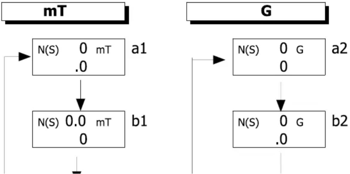
- Press the MODE - DC AC button (7) to switch through the measurement settings and resolutions. Each further press of the button switches one step further in the loop. Measuring mode for the DC fields is indicated with the display symbol 'N (S)'
- Measurement settings a1 (resolution 0.1) and b1 (resolution 0.01) (see the figure below) are used for measurement of DC magnetic fields in unit mT.
- Measurement settings a2 (resolution 1) and b2 (resolution 0.1) (see the figure below) are used for measurement of DC magnetic fields in unit G.
One of the two sequences indicated below is switched according to the unit selected. Switch the unit of measurement to select the other unit of measurement and therefore the other sequence. See Section 'c) Selecting the unit of measurement'.
- Place the sensor with sensor head (16) on the object to be measured. The sensor head (15) must touch the object.
- The measured value is displayed on the LC display (3) together with the polarity (N/S) of the field. If you move the sensor head (15), move it as slowly and as smoothly as possible along the test section. This allows you to keep track of the positions at which the polarity changes.
- After you finish measuring, always switch off the measuring device.
If the measurement range is exceeded upwards or downwards, 'OL' is shown on the LC display (3).
d) Measuring AC magnetic fields (changing)
AC magnetic fields occur in AC coils such as transformers. The magnetic field lines change direction. The measuring device can measure AC fields from 50 Hz to 60 Hz. Proceeds as follows for AC measurement:
- Switch on the measuring device.
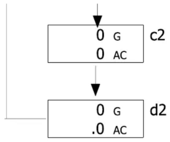
- Press the MODE - DC AC button (7) to switch through the measurement settings and resolutions. Each further press of the button switches one step further in the loop. Measuring mode for the AC fields is indicated with the display symbol 'AC'.
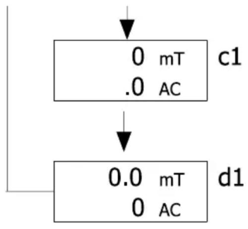
- Measurement settings c1 (resolution 0.1) and d1 (resolution 0.01) (see the figure below) are used for measurement of AC magnetic fields in unit mT.
- Measurement settings c2 (resolution 1) and d2 (resolution 0.1) (see the figure below) are used for measurement of AC magnetic fields in unit G.

One of the two sequences indicated below is switched according to the unit selected. Switch the unit of measurement to select the other unit of measurement and therefore the other sequence. See Section 'c) Selecting the unit of measurement'.
- Place the sensor with sensor head (16) on the object to be measured. The sensor head must touch the object.
- The measured value is displayed on the LC display (3) without the polarity (N/S) of the field. The symbol 'AC' indicates measurement in AC field mode. In AC magnetic fields, the polarity constantly changes.
- After you finish measuring, always switch off the measuring device.

If the measurement range is exceeded upwards or downwards, 'OL' is shown on the LC display (3).
e) REC measured value memory
The measured value memory records the minimum and maximum field strength values.
- Press the REC button (6) to activate the REC function in measuring mode. 'REC' appears on the LC display (3) in conjunction with a beep. This indicates that measurement recording is active.
Maximum values
- Press the REC button (6) while recording is active to retrieve the maximum values. The 'RECMAX' symbol appears on the display and the value is loaded from the memory and displayed.
- To delete the maximum value from the memory, press the HOLD button (5). 'RECMAX' goes out and only 'REC' remains on the LC display (3). This means that recording continues.
Minimum values
- Press the REC button (6) again while the REC function is active to retrieve the minimum values. The minimum values are displayed together with 'RECMIN'.
- To delete the minimum value from the memory, press the HOLD button (5). 'RECMIN' goes out and only 'REC' remains on the LC display (3). This means that recording continues.
- To deactivate the REC function, press and hold the REC button (6): for approx. 2 seconds. The 'REC' symbol goes out. The currently measured field strength value appears on the LC display (3) again.

The saved measured values are retained in REC mode only. If this function is terminated or the measuring device is switched off, the memory is deleted.
If you carry out measurements on DC (static) magnetic fields and the REC memory function is switched on, the north pole N or south pole S indicator cannot change during the measurement. A maximum/minimum value is based on natural fluctuation of the field strength in the area of a pole.
f) RS232 port
The measuring device is fitted with a serial interface (8) for exchanging data with a computer. This can be found on the right hand side under a cover.
- Open the flap with a pointed object.
- The interface is in the form of a 3.5mm jack socket RS232 OUTPUT (8).
- It requires a special data cable (not included) for the transmission of a 16-digit signal. The data cable has the following components:
3.5 mm jack, mono 9-pin D-SUB socket for PC
Centre contact Pin 4
External contact Pin 2
A 2.2 KOhm resistor must be fitted between pin 2 and pin 5.
The serial data signal is made up of 16 bits in the following order:
D10 Polarity; 0 = positive, 1 = negative
D9 Decimal point (DP) at the corresponding point from right to left; 0 = no decimal point
1 = 1 decimal point
2 = 2 decimal points
3 = 3 decimal points
D8 to D1 Measured value D8 = largest figure (MSD), D1 = lowest figure (LSD). If 1234 is displayed, the bit rate is: '00001234'
D0 End signal
RS232 port
Baud rate: 9600
Parity No parity
Number of data bits Number of data bits
Stop bit 1 stop bit
g) Restoring the default settings
If you experience problems with the measuring device, for example, in the event of a system freeze, reset the device. Proceed as follows:
- Open the side flap. See Section f) RS232 interface'.
- When the measuring device is switched on, press the RESET button (9) with a pointed object. All previous settings are reset set to the default values. The settings may need to be adjusted again.
11. Troubleshooting
Error Potential cause Remedy/potential solution
The measuring device cannot be switched on.
Are the batteries flat? Check the battery status. Reset the
measuring device by pressing the RESET button (9).
A stable measured value cannot be displayed.
Wrong measurement? Has the sensor been moved too forcefully?
Hold the sensor still.
Has the correct measuring mode been selected?
Check whether the set measuring mode (AC or DC) is suitable for your object.
The measuring device cannot be operated.
Undefined system status. Reset the measuring device by
pressing the RESET button (9).
12. Care and cleaning

Never use aggressive detergents, rubbing alcohol or other chemical solutions, as these can damage the casing or even impair the function.
- Always disconnect the product from the power supply before cleaning it.
- Use a dry, lint-free cloth to clean the product.
13. Disposal
a) Product
Electronic devices are recyclable waste and must not be placed in household waste. At the end of its service life, dispose of the product according to the relevant statutory regulations. Remove any inserted battery and dispose of it separately from the product.
b) Battery information

You are required by law to return all used batteries (Battery Directive). They must not be placed in household waste.
Batteries containing hazardous substances are labelled with this symbol to indicate that disposal in household waste is forbidden. The abbreviations for heavy metals in batteries are: Cd = Cadmium, Hg = Mercury, Pb = Lead (indicated on the battery, e.g. below the waste bin icon on the left).
Used batteries can be returned to local collection points, our stores or battery retailers.
You thus fulfil your statutory obligations and contribute to environmental protection.
14. Technical specifications
| Power supply | .9 V/DC (alkaline battery)AC/DC AP-9 VA (power adaptor not included, must be purchased separately) |
| Input current | .15 mA (in operation) |
| Standby | .0.0 μA |
| Battery life | .Approx. 9 hours in continuous use. |
| Sensor | .Hall effect sensor with automatic temperature compensation (ATC) |
| Units of measurement | .G (Gauss), mT (millitesla) |
| Fields | .DC and AC field measurement |
| Measurement ranges (DC) | .300 mT x 0.01 mT/ 3000 mT x 0.1 mT or 3000 G x 0.1 G / 30000 G x 1 G |
| Field strength (AC) | .150 mT x 0.01 mT/ 1500 mT x 0.1 mT or 1500 G x 0.1 G/15000 G x 1 G |
| Accuracy | .At 23 °C ± 5 °C, DC ± (5 % rdg. + 10 digit);AC ± (5 % rdg. + 20 digit) |
| Resolution | .0.01/ 0.1 mT, 0.1/ 1 G |
| Frequency range | .50/60 Hz (for AC) |
| Pole indication | .North pole/south pole |
| Field direction | .Uniaxial |
| Data connection | .RS232 |
| Display size | .52 x 38 mm (dual LC display) |
| Display sampling | .Approx. 1 second |
| Cable length | .Approx. 105 cm (sensor) |
| Operating conditions | .0 to +50 °C, <85 % relative humidity (non-condensing) |
| Storage conditions | .-20 to +60 °C, <75 % relative humidity (non-condensing) |
| Dimensions (L x W x H) | .198 x 68 x 30 mm (device) |
| Dimensions (L x W x Ø) | .195 x 25 x 19 mm (sensor) |
| Weight | .275 g (total) |
Table des matieres
Page
France (email): technique@conrad-france.fr