VC64 - Measuring equipment VOLTCRAFT - Free user manual and instructions
Find the device manual for free VC64 VOLTCRAFT in PDF.

User questions about VC64 VOLTCRAFT
0 question about this device. Answer the ones you know or ask your own.
Ask a new question about this device
Download the instructions for your Measuring equipment in PDF format for free! Find your manual VC64 - VOLTCRAFT and take your electronic device back in hand. On this page are published all the documents necessary for the use of your device. VC64 by VOLTCRAFT.
USER MANUAL VC64 VOLTCRAFT
The two-pole voltage tester can be used to measure and display DC and AC voltages in an electrical low-voltage circuit. The product also has an acoustic and visual circuit indicator as well as a resistance measurement and an RCD test function. Power is supplied by two batteries of type AAA/Micro included in the delivery.
The voltage tester complies with the standard for two-pole voltage testers of 12 - 690 V, CAT III 1000 V, CAT IV 600 V according to EN 61243-3:2014/EN 60529 as well as protection class IP64 (dust and spray water). The product is suitable for use in dry or damp conditions. Use during rain or other precipitation is not permitted. The voltage tester is designed for use by electrically skilled persons using personal protective equipment.
The measuring instrument must not be operated when the battery compartment is open.
Measuring under adverse ambient conditions such as dust and flammable gases, vapours or solvents is not permitted.
Always observe the safety instructions and all other information included in these operating instructions. This product complies with the applicable national and European requirements. All names of companies and products are the trademarks of the respective owners. All rights reserved.
PACKAGE CONTENTS
Voltage tester
- 2x batteries of type Micro/AAA
- 2x protective plastic covers
- 2x4 mm adapter to open probe tips
- Operating instructions
EXPLANATION OF SYMBOLS

The lightening flash symbol in a triangle warns against the risk of an electric shock or interference with the electrical safety of the device.

An exclamation mark inside a triangle refers to important. notes in the operating instructions.

The arrow symbol indicates special information and advice on operating the device.
SAFETY INSTRUCTIONS
The warranty will expire in case of any damage caused by the failure to follow these operating instructions! We assume no liability for any resulting consequential damage! I am no liability for any damage to property or personal injuries caused by improper use or non-compliance with the safety instructions! In such cases, the warranty will be null and void.
The unauthorised conversion and/or modification of the product is not permitted for safety and approval reasons. Do not disassemble the product.
- This product is not a toy. Therefore, be especially careful when children are around. Use the product where it is out of the reach of children.
- Never use the product immediately after it has been taken from a cold room to a warm one. The condensation that forms can ruin the product under certain circumstances.
- Avoid the following adverse conditions at the location of installation and during tran
- Extreme cold or heat, direct sunlight
- Dust or flammable gases, fumes or solvents
Strong impacts, blows
- Do not leave packaging material carelessly lying around, since it could become a dangerous plaything for children.
- Handle the product with care, it can be damaged by impacts, blows, or accidental falls, even from a low height.
- Never touch the measuring tips or a measuring point during the measuring process. There is a risk of electric shock.
-
Never touch areas outside of the marked handling area during a measurement.
-
Do not use in the immediate proximity of strong magnetic or electromagnetic fields or transmission aerials. These can affect the measurement.
- Prior to and after each measurement, check your instrument and the measuring leads for damages. Never take any measurements if the protecting insulation is defective or the measuring instrument is damaged otherwise.

- Be especially careful when dealing with voltages higher than 50 V/AC or 75 V/DC. Even at such voltages you can get a life-threatening electric shock if you come into contact with live electric wires.
The measuring instrument is suitable for use in dry or damp conditions. Avoid use in a damp or wet environment.
- Always ensure that the probe tips are perfectly clean. Dirty or even corroded test clips can lead to an incorrect measurement.
- The test probes must only be touched at the handles provided for this purpose. Otherwise, there is danger of an electric shock.
- Never exceed the highest permissible voltage values. If the stated values are exceeded, the product becomes damaged and poses a hazard that can be fatal. (See chapter "Technical data").
The recovery time as specified in "Technical data" must always be adhered to. Otherwise, the product could be damaged.
The voltage values specified are nominal voltages.
If the neutral wire (N) or the earth wire (PE) is interrupted, no reading is shown.
- The measuring instrument must only be used within the permissible ambient conditions (see chapter "Technical data").
Always attach the measuring tip cover if you are no longer using the device.
- Store the measuring instrument in a dry place, protected against dust, if you are no longer using it.
- When using the voltage tester in the measurement category CAT III and CAT IV, it is recommended to attach the plastic protective covers to the test probes to decrease the length of the free contact tips. This reduces the risk of a possible short circuit during testing.
- Depending on the internal impedance of the voltage tester, there are different ways of displaying "operating voltage present" or "operating voltage not present" in the presence of interference voltage.
- A voltage tester with relatively low internal impedance does not display all interference voltages with an initial value above ELV, compared to the reference value of 100k . Upon contact with the parts to be tested, the voltage tester may temporarily reduce the interference voltage by discharging to a level below ELV; however, after removing the voltage detector, the interference voltage will assume its original value again.
-
When the notification "voltage present" does not appear, it is strongly recommended that you insert the earthing device before starting work.
-
A voltage tester with relatively high internal impedance will not clearly display "operating voltage present" in the event of existing interference voltage, compared to the reference value of 100k
- When "voltage present" appears on a part which is considered disconnected from the system, it is strongly recommended to check the state "operating voltage not present" with additional measures (e.g., using a suitable voltage tester, visual inspection of the disconnection point in the electrical network, etc.) to make sure the voltage indicated by the voltage tester is not a fault.
- A voltage tester indicating two values of the internal impedance has passed the design test for handling interference voltages and is able to differentiate (within technical limits) the operating voltage from the interference voltage and directly or indirectly display the existing voltage type.
CATI Measurement Category I is applicable to measuring circuits of electrical and electronic equipment that is not directly supplied with mains voltage (battery-operated devices, etc.)
CAT II Measurement Category II is applicable to measuring circuits of electrical and electronic equipment that is directly supplied with the mains voltage via a power plug. This category also covers all smaller categories (e.g. CAT I for measuring signal and control voltages).
CAT III Measurement Category III is applicable to measuring circuits of installations in buildings (e.g. electric sockets or sub-distributions). This category also covers all smaller categories (e.g. CAT II for measuring electronic devices).
CATIV Measurement Category IV is applicable to measuring at the origin of the low-voltage installation (e.g. main distribution, electricity provider's transfer points to homes, etc.) and outdoors. This category also contains all lower categories.
GENERAL BATTERY INSTRUCTIONS
- Batteries should be kept out of the reach of children.
- Do not leave batteries lying around in the open; there is a risk of them being swallowed by children or pets. If they are swallowed, consult a doctor immediately.
Leaking or damaged batteries can lead to caustic burning of the skin. Therefore, use suitable protective gloves. - Batteries must not be short-circuited, opened or thrown into fire. There is a risk of explosion.
- Make sure that the polarity is correct when inserting the batteries (pay attention to plus/+ and minus/-).
DESCRIPTION OF SYMBOLS
| ~ | Alternating current (AC) |
| V AC DC | V/AC: Alternating voltage V/DC: Direct current |
| 12/24/36/50/120/230/400/690 Displ ay of rated voltage range in voit (V) | |
| + | Direct current positive potential DC |
| - | Direct current negative potential DC |
| kΩ Electrical resistance in kiloohm | |
| Hz Electrical frequency (Hertz) | |
| 4 | Single-pole phase display 100 - 690 V as well as warning for hazardous voltage (>50 V/AC, >120 V/DC) Operation also possible with flat batteries or without batteries |
| Symbol for continuity check | |
| + | Battery symbol for used battery |
| CE | Conformity symbol, CE-approved |
| Device and equipment for working under voltage. Personal protective measures required. | |
| Protection class 2 (double or reinforced insulation/protective insulation) | |
INSERTING/ REPLACING BATTERIES
Disconnect the voltage tester from the respective measurement object.
Hold both measuring tips together. If no signal sounds or an empty battery symbol appears on the display, the batteries must be replaced. To protect your safety, attach the two plastic covers/measuring tip covers. For this purpose, loosen the screw (18) using a small Phillips head screwdriver. Now, carefully pull the battery compartment (17) downwards along the cable. Remove the empty batteries from the measuring instrument, where applicable, and insert new batteries of the same type (see "Technical Data") into the battery compartment observing the correct polarity. The use of rechargeable batteries is not permitted. We recommend to use alkaline batteries. They guarantee a long service life. Slide the battery compartment back upwards until you feel it click in place and carefully close the compartment with the screw (18).
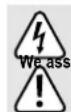
CONTROLS
1 Measuring tips
2 Test probe
3 Test probe “+”
4 Holder for second measuring line
5 LED hazardous voltage
6 AC or DC voltage indicator
7 Continuity or hold indicator
8 Voltage indicator
9 Ohm indicator
10 Winding direction indicator
11 Load indicator
12 Bar graph indicator
13 Empty battery indicator
14 Load button
15 Button for measuring tip light
16 Button for hold/ohm measurement
17 Battery compartment
18 Screw for battery compartment
FUNCTIONALITY TEST/SELF-TEST
We recommend to test the functionality of the measuring instrument before each measurement.
Hold both measuring tips together. A signal will sound and the symbol (7) will turn on. The product is ready for operation.
The measuring instrument switches on automatically when the respective measurement unit is detected.
After a measurement, the measuring instrument turns off automatically to save power.
If no signal sounds, replace the batteries. If functionality is not given even after replacing the batteries, the product must not be used!
Additional self test function (all LED, TORCH, BUZZER are ON for 2 sec) is implemented for all Contra
VTs. It can be started when VT is off. The user need to push Torch button (15) and hold for 4 sec. After that all LED/symbols light, Torch light and buzzer sound is active for 2 sec.

Always attach the measuring tip cover if you are no longer using the device.
The single-pole phase tester works at a voltage of at least 100 V/AC without counter potential.
Keep in mind that the output can be affected when measuring outer conductors with e.g. strongly insulating protective equipment or at insulating locations.

A single-pole phase tester cannot be used to test de-energised conditions!
VOLTAGE TESTING/PHASE ROTATION DIRECTION
The LCD display (8) shows the measured voltage (AC/DC), the phase rotation direction < L or R> (100 V AC and higher) and the measurement range in the bar chart. The display can be paused for approx. 30 seconds by pressing the Hold button (16).
Connect the two measuring tips with the object to be measured.
The voltage tester automatically switches on when it detects a voltage of 12V or higher.
When using the voltage tester in the measurement category CAT III and CAT IV, it is recommended to attach the plastic protective covers provided to the test probes (2) and (3) to decrease the length of the free contact tips. This reduces the risk of a possible short circuit during testing.
For ease of use, the product has a holder (4) for a second measurement line. This makes measuring e.g. directly via mains sockets easier.

For direct current, the polarity of the voltage displayed refers to the measuring tip of the measuring instrument (3).

When the batteries are empty, only the warning indicator (5) for "Dangerous Voltage" will function when the test voltage reaches 50 V/AC or 120 V/DC. Do not ever touch the measuring contacts, if this indicator is on. Change the batteries.
CONTINUITY TEST

Before a continuity test, make sure that the measurement object is de-energised.
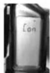
Connect the two measuring tips with the object to be measured. A signal will sound and the LCD will show the continuity symbol (7) and Con, if the continuity is max. 400k +50%
Disconnect the measuring tips from the measurement object after the measurement.
RESISTANCE MEASUREMENT
To activate the electrical resistance measurement function, press the "hold" button (16) for about
3 seconds. The measurement unit switches to the electrical resistance measurement function.
Now you can connect the two test prods on the object to be measured.
The measured amount of electrical resistance is showed on the display.
By pressing the "hold" button briefly, the measurement results can be frozen.

Make sure that the object to be measured is not under voltage!
RCD TEST (GFCI TEST)
The circuit tester can check the function of the FI.

The voltage tester can only check the function of the residual current device. The test and trip
ping current, as well as the tripping time, cannot be determined!
Connect the measuring tip (2) with the protective earth conductor and the measuring tip (3) with the phase.
Press the red button (14) and the red button (14a) at the same time.
MEASURING POINT LIGHTING
The measurement device has LED illumination mounted on the top of the casing to allow measurements in dim light. To activate this function press the button (15). The LED turns off automatically after about 30 seconds to spare the battery.
MAINTENANCE AND CLEANING
Apart from the occasional battery change, the product is maintenance-free for you.
However, in order to ensure the accuracy of the measurement device over a long period, it is recommended to have the device calibrated once a year.
Never clean the product while it is connected to a voltage source. Use a clean, dry, soft cloth for cleaning. Do not use aggressive cleaning agents, as these can cause discolouration. To prevent scratch marks, do not press too strongly on the surface when cleaning.
DISPOSAL
a) General Instructions


Please dispose of the unserviceable product according to the relevant statutory requirements.
Remove any inserted batteries and dispose of them separately from the product.
b) Batteries
As the end user, you are required by law (Regulation on Spent Batteries) to return all dead batteries and accumulators. Disposal in the household waste is prohibited.

Batteries containing hazardous substances are labelled with the symbol opposite indicating that
disposal in the domestic waste is forbidden. The symbols of the critical heavy metals are: Cd =
Cadmium, Hg = Mercury, Pb = Lead.
You can return your used batteries/rechargeable batteries free of charge to the official collection points in your municipality, in our stores, or anywhere batteries or rechargeable batteries are sold.
TECHNICAL DATA
Voltage range 12-690 V (DC/AC)
Frequency range. 0 Hz; 16 - 400 Hz
LCD resolution. 12, 24, 36, 50, 120, 230, 400, 690 V
Measurement tolerance for voltage check. +/- (3% + 5 digit)
DC/AC voltage recognition automatic
Auto-Power-On. >12 V (DC/AC)
Response time. <1 s
Resistance range. 0-19 99Ohm
Max measurement time (RCD test) 30 s
Regeneration time (RCD test) 240 s
Max. test current (RCD test) 30 mA/230V
Max. Current without RCD burden <3.5 mA/690 V
Measurement category...CAT IV 600 V/CAT III 1000 V
Norms EN 60529 and EN 61243-3:2014
Kind of protection.. IP64
Level of contamination. 2
Temperature range. -15oC to +45oC
Humidity. max. 85% relative humidity, not condensing
Altitude over sea level max. 2000 m
Length of measurement cable. ca. 93 cm
Current supply. 2 type AAA/Micro batteries
Weight 130g
Dimensions. 67 x 205 x 27 mm (B x H x T)
CONTINUITY TEST
| Indication optic and acoustic (<400 kΩ +50%) | |
| Test current <5 uA | |
| Overvoltage protection 690 V (DC/AC) |

MODE D'EMPLOI
C
VERSION 10/17
TESTEUR DE TENSION BIPOLAIRE VC64
N° DE COMMANDE 1313886
UTILISATION CONFORME
Plage de tension. 12-690 V (CC/CA)
Dimensions. 67 x 205 x 27 mm (L x H x P)
CONTRÔL DE CONTINUITE
LCD-oplossing. 12,24,36,50,120,230,400,690V
Meetolerantie van de spanningestost. +l - (3% +5 Digit)