
CF 75 - Heating Master - Free user manual and instructions
Find the device manual for free CF 75 Master in PDF.

| Product type | Gas warm air heater |
| Brand | Master |
| Model | CF 75 |
| Category | Heating |
| Fuel | Natural gas (G20/G25) or propane (LPG) |
| Use | Indoor or outdoor (with specific kit) |
| Thermal efficiency | Maximum |
| Thermal inertia | Low |
| Main functions | Heating and ventilation (fan only) |
| Installation | Fixed to ceiling or wall by authorized technician |
| Safety | Safety thermostat, shutdown on ignition failure, overheating protection |
| Routine maintenance | External cleaning with non-abrasive damp cloth |
| Periodic maintenance | At least once a year by approved center |
| Warranty | 12 months (parts only) |
| Optional accessories | Outdoor kit, room thermostat, diffuser |
| Operation indicator | Light indicator (off = normal, steady on = blockage) |
| Gas conversion | Possible (nozzle and valve adjustment by authorized technician) |
Frequently Asked Questions - CF 75 Master
User questions about CF 75 Master
0 question about this device. Answer the ones you know or ask your own.
Ask a new question about this device
Download the instructions for your Heating in PDF format for free! Find your manual CF 75 - Master and take your electronic device back in hand. On this page are published all the documents necessary for the use of your device. CF 75 by Master.
USER MANUAL CF 75 Master
natural_image
Icon of an open book with an exclamation mark, enclosed in a diamond shape with a yellow diagonal stripe (no text or symbols)USER AND MAINTENANCE MANUAL
CF 75 - CF 75A
| en | it | de | es | fr | pl | ru | hu | sk | bg | zh |
NOTE:
TECHNICAL DATA - DATI TECNICI - TECHNISCHE DATEN - DATOS TÉCNICOS - DONNÉES TECHNIQUES - TECHNISCHE GEGEVENS - DADOS TÉCNICOS - TEKNISKE DATA - TEKNISET TIEDOT - TEKNISKE DATA - TEKNISKA DATA - DANE TECHNICZNE - TEXНИЧЕСКИЕ ДАННЫЕ - TECHNICKÉ ÚDAJE - MŰSZAKI ADATOK - TEHNIČNI PODATKI - TEKNÍK VERÍLER - TEHNIČKI PODACI - TECHNINIAI DUOMENYS - TEHNISKIE DATI - TEHNILISED ANDMED - DATE TEHNICE - TECHNICKÉ ÚDAJE - TEXНИЧЕСКИ ДАННИ - TEXNICHÍ DAHI - TEHNIČKI PODACI - TEXNIKA
ΔΕΔΟΜΕΝΑ - 技术参数
CF 75
| AL-BG-CZ-SI-HR-LT-MK-SK-TR-RO-AT-CH-DK-CY-EE-FI-IE-IT-SE-NO-GB-PT-ES | HU BE DE FR PL NL | DK-FI-NL-NO-SE-AL-BG-CZ-SI-HR-LT-MK-SK-TR-RO-MT-CY-EE-HU | AT-CH-DE PL | BE-CH-ES-FR-GB-IR-IT-PT | BE-ES-FR-GB-IR-PT-IE | CH-DE-NL | ||||||||
| CAT. | I_2H | I_2H | I_2E(H)B | I_2ELL | I_2Esl - I_2Er | I_2E | I_2L | I_3B/P | I_3B/P | I_3B/P | I_3+ | I_3P | I_3P | |
| GAS | G 20 | G 20 | G 20 | G 20 | G 25 | G 20 / G 25 | G 20 | G 25 | G 30 / G 31 | G 30 / G 31 | G 30 / G 31 | G 31 | G 31 | |
| [mbar] | 20 | 25 | 20 | 20 | 20 / 25 | 20 | 25 | 28 - 30 | 50 | 37 | 28 - 30 / 37 | 37 | 50 | |
| P min. | [mbar] | 17 | 18 | 17 | 17 | 17 | 17 | 20 | 25 | 42,5 | 25 | 25 | 25 | 42,5 |
| P max. | [mbar] | 25 | 33 | 25 | 25 | 30 | 25 | 30 | 35 | 57,5 | 45 | 45 | 45 | 57,5 |
| [mbar] | 7 | 9 | 20 | 25 | ||||||||||
| NOZZLE ∅ | [mm] | 10 | 5 | |||||||||||
| Qn | [kW] | 75 | 75 | |||||||||||
| GAS CONS. | [m^3/h] | 7,7 | 9,2 | 2,3 | 2,3 | 2,3 | 2,3 | 3,1 | 3,1 | |||||
| POWER SUPPLY | [V / Hz / A] | ~220-240 V 50 Hz 2,8 A | ~220-240 V 50 Hz 2,8 A | |||||||||||
| CATEGORY | A2 | A2 | ||||||||||||
| FAN | [m^3/h] | 2.100 | 2.100 | |||||||||||
| ATTENTION: Pin: MAX 60 mbar |
| TEMPERATURE LIMIT: -20°C ÷ +40°C |
TECHNICAL DATA - DATI TECNICI - TECHNISCHE DATEN - DATOS TÉCNICOS - DONNÉES TECHNIQUES - TECHNISCHE GEGEVENS - DADOS TÉCNICOS - TEKNISKE DATA - TEKNISET TIEDOT - TEKNISKE DATA - TEKNISKA DATA - DANE TECHNICZNE - TEXНИЧЕСКИЕ ДАННЫЕ - TECHNICKÉ ÚDAJE - MŰSZAKI ADATOK - TEHNIČNI PODATKI - TEKNÍK VERÍLER - TEHNIČKI PODACI - TECHNINIAI DUOMENYS - TEHNISKIE DATI - TEHNILISED ANDMED - DATE TEHNICE - TECHNICKÉ ÚDAJE - TEXНИЧЕСКИ ДАННИ - TEXNICHÍ DANI - TEHNIČKI PODACI - TEXNIKA
ΔΕΔΟΜΕΝΑ - 技术参数技术参数
| CF 75A | ||||||
| CAT. | I_2H | I_2E | I_2L | I_3B/P | I_3P | |
| GAS | G 20 G 25 | G 30 / G 31 | G 31 | |||
| [mbar] | 20-55 | 30-55 | ||||
| [mbar] | 7 | 9 | 20 | 25 | ||
| NOZZLE ∅ | [mm] | 10 | 5 | |||
| Qn | [kW] | 75 | 75 | |||
| GAS CONS. | [m^3/h] | 7,7 | 9,2 | 2,3 | 3,1 | |
| POWER SUPPLY | [V / Hz / A] | ~220-240 V 50 Hz 2,8 A | ~220-240 V 50 Hz 2,8 A | |||
| CATEGORY | A2 | A2 | ||||
| FAN | [m^3/h] | 2.100 | 2.100 | |||
| ATTENTION: Pin: MAX 60 mbar |
| TEMPERATURE LIMIT: -20°C ÷ +40°C |


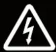
IMPORTANT SETUP:
flowchart
graph TD
    A["Pressure setting"] --> B["N.G.: 7 mbar L.P.G.: 20 mbar"]
    A --> C["30÷50 mbar"]
    D["Gas flow"] --> E["Rigid Tube"]
    E --> F["Gas Regulator: Gas flow >10 m³/h"]
    G["Pressure setting"] --> H["Pressure setting suggest: 30÷50 mbar"]
    I["Pressure setting"] --> J["Pressure setting suggest: N.G.: 7 mbar L.P.G.: 20 mbar"]
    K["Pressure setting"] --> L["Pressure setting suggest: N.G.: 7 mbar L.P.G.: 20 mbar"]
    M["Pressure setting"] --> N["Pressure setting suggest: N.G.: 7 mbar L.P.G.: 20 mbar"]
    O["Pressure setting"] --> P["Pressure setting suggest: N.G.: 7 mbar L.P.G.: 20 mbar"]
    Q["Pressure setting"] --> R["Pressure setting suggest: N.G.: 7 mbar L.P.G.: 20 mbar"]
    S["Pressure setting"] --> T["Pressure setting suggest: N.G.: 7 mbar L.P.G.: 20 mbar"]
    U["Pressure setting"] --> V["Pressure setting suggest: N.G.: 7 mbar L.P.G.: 20 mbar"]
    W["Pressure setting"] --> X["Pressure setting suggest: N.G.: 7 mbar L.P.G.: 20 mbar"]
    Y["Pressure setting"] --> Z["Pressure setting suggest: N.G.: 7 mbar L.P.G.: 20 mbar"]
    AA["Pressure setting"] --> AB["Pressure setting suggest: N.G.: 7 mbar L.P.G.: 20 mbar"]
    AC["Pressure setting"] --> AD["Pressure setting suggest: N.G.: 7 mbar L.P.G.: 20 mbar"]
    AE["Pressure setting"] --> AF["Pressure setting suggest: N.G.: 7 mbar L.P.G.: 20 mbar"]
    AG["Pressure setting"] --> AH["Pressure setting suggest: N.G.: 7 mbar L.P.G.: 20 mbar"]
    AI["Pressure setting"] --> AJ["Pressure setting suggest: N.G.: 7 mbar L.P.G.: 20 mbar"]
    AK["Pressure setting"] --> AL["Pressure setting suggest: N.G.: 7 mbar L.P.G.: 20 mbar"]
    AM["Pressure setting"] --> AN["Pressure setting suggest: N.G.: 7 mbar L.P.G.: 20 mbar"]
    AO["Pressure setting"] --> AP["Pressure setting suggest: N.G.: 7 mbar L.P.G.: 20 mbar"]
    AQ["Pressure setting"] --> AR["Pressure setting suggest: N.G.: 7 mbar L.P.G.: 20 mbar"]
    AS["Pressure setting"] --> AT["Pressure setting suggest: N.G.: 7 mbar L.P.G.: 20 mbar"]
    AU["Pressure setting"] --> AV["Pressure setting suggest: N.G.: 7 mbar L.P.G.: 20 mbar"]
    AW["Pressure setting"] --> AX["Pressure setting suggest: N.G.: 7 mbar L.P.G.: 20 mbar"]
    AY["Pressure setting"] --> AZ["Pressure setting suggest: N.G.: 7 mbar L.P.G.: 20 mbar"]
    BA["Pressure setting"] --> BB["Pressure setting suggest: N.G.: 7 mbar L.P.G.: 20 mbar"]
    BC["Pressure setting"] --> BD["Pressure setting suggest: N.G.: 7 mbar L.P.G.: 20 mbar"]
    BE["Pressure setting"] --> BF["Pressure setting suggest: N.G.: 7 mbar L.P.G.: 20 mbar"]
    BG["Pressure setting"] --> BH["Pressure setting suggest: N.G.: 7 mbar L.P.G.: 20 mbar"]
    BI["Pressure setting"] --> BJ["Pressure setting suggest: N.G.: 7 mbar L.P.G.: 20 mbar"]
    BK["Pressure setting"] --> BL["Pressure setting suggest: N.G.: 7 mbar L.P.G.: 20 mbar"]
    BM["Pressure setting"] --> BN["Pressure setting suggest: N.G.: 7 mbar L.P.G.: 20 mbar"]
    BO["Pressure setting"] --> BP["Pressure setting suggest: N.G.: 7 mbar L.P.G.: 20 mbar"]
    BP --> BQ["Pressure setting"]
    BR["Pressure setting"] --> BS["Pressure setting suggest: N.G.: 7 mbar L.P.G.: 20 mbar"]
    BT["Pressure setting"] --> BU["Pressure setting suggest: N.G.: 7 mbar L.P.G.: 20 mbar"]
    BV["Pressure setting"] --> BW["Pressure setting suggest: N.G.: 7 mbar L.P.G.: 20 mbar"]
    BX["Pressure setting"] --> BY["Pressure setting suggest: N.G.: 7 mbar L.P.G.: 20 mbar"]
    BZ["Gas flow"] --> CA["Gas flow from left to right, indicated by <0.8m width"]
▶en - STRICTLY COMPLY WITH ALL THE INDICATIONS IN THIS LABEL IN ORDER TO OBTAIN THE CORRECT OPERATION OF THE HEATER. - Only use professional and perfectly calibrated equipment to set up the heaters (pressure gauges with MAX resolution 1 mbar). - (*) The set-up must be performed when all heaters, connected to the same gas supply line, are running (simultaneous use).
▶it - SEGUIRE SCRUPOLOSAMENTE TUTTE LE INDICAZIONI RIPORTATE IN QUESTA ETICHETTA, AL FINE DI OTTENERE IL CORRETTO FUNZIONAMENTO DEL RISCALDATORE. - Per il settaggio dei riscaldatori usare solo attrezzatura professionale e perfettamente tarata (manometri con risoluzione MAX. 1 mbar). - (*) Il settaggio va eseguito quando tutti i riscaldatori, connessi alla stessa linea di alimentazione gas, sono in funzione (uso simultaneo).
▶ de - UM DAS HEIZGERÄT ORDNUNGSGEMÄSS ZU BETREIBEN, ÄLLE AUF DIESEM ETIKETT AUFGEFÜHRT-EN ANLEITUNGEN BEFOLGEN. - Für die Einstellung der Heizgeräte nur eine professionelle und einwandfrei kalibrierte Ausrüstung verwenden (Manometer mit MAX. Auflösung 1 mbar). - (*) Die Einstellung darf erst vorgenommen werden, wenn alle an derselben Gasversorgungsleitung angeschlossenen Heizgeräte in Betrieb sind (gleichzeitige Verwendung).
es - SIGA ESCRUPULOSAMENTE TODAS LAS INDICACIONES CONTENIDAS EN ESTA ETIQUETA PARA OBTENER EL CORRECTO FUNCIONAMIENTO DEL CALEFACTOR. - Para regular los calefactores, utilice solo un equipo profesional y correctamente calibrado (manómetros con resolución MÁX. de 1 mbares). - (*) La regulación deberá realizarse cuando todos los calefactores, conectados a la misma línea de alimentación de gas, estén en funcionamiento (uso simultáneo).
▶fr - SUIVRE SCRUPULEUSEMENT TOUTES LES INDICATIONS REPORTÉES SUR CETTE ÉTIQUETTE, AFIN D'OBTENIR LE FONCTIONNEMENT APPROPRIÉ DE L'APPAREIL DE CHAUFFAGE. - Pour le réglage des appareils de chauffage, n'utiliser que du matériel professionnel et parfaitement étalonné (manomètres à résolution MAX. 1 mbar). - (*) Le réglage doit être effectué lorsque tous les appareils de chauffage, connectés à la même conduite d'alimentation en gaz, fonctionnent (utilisation simultanée).
▶ ru - ДЛЯ ПРАВИЛЬНОЙ РАБОТЫ ОБОГРЕВАТЕЛЯ СТРОГО СЛЕДОВАТЬ ВСЕМ УКАЗАНИЯМ, ПРИВЕДЕН НЫМ НА ЭТИКЕТКЕ. - Для настройки обогревателей пользоваться только профессиональными и правильно т арированными приборами (манометры с разрешением МАКС. 1 мбар). - (*) Настройка должна выполняться. ко гда все обогреватели, подсоединенные к одной линии подачи газ, находятся в работе (одновременное использование).
zh - 严格遵守本标签内的一切说明,从而实现加热器的正确运行。- 为了设置加热器,只能使用精确校准的专业设备(最大分辨率为1 mbar的压力表)。-(*) 当连接到同一天然气供应线的所有加热器都在运行时(同时使用),必须执行此设置。
NOTE:
PICTURES - FIGURE - ABBILDUNGEN - FIGURAS - FIGURES - FIGUREN - FIGURAS - FIGURER - KUVAT - FIGURER - FIGURER - ILUSTRACJE - ИЛЛЮСТРАЦИИ - OBRÁZKY - ÁBRÁK - SLIKE - ŞEKİLLER - SLIKE - ILIUSTRACIJOS - ATTĚLI - JOONISED - IMAGINI - OBRÁZKY - CXEMI - МАЛЮНКИ - SLIKE - EIKONEΣ - 图示
natural_image
Close-up of a metallic connector with threaded end and mounting holes, mounted on a transparent panel (no visible text or symbols)PICTURES - FIGURE - ABBILDUNGEN - FIGURAS - FIGURES - FIGUREN - FIGURAS - FIGURER - KUVAT - FIGURER - FIGURER - ILUSTRACJE - ИЛЛЮСТРАЦИИ - OBRÁZKY - ÁBRÁK - SLIKE - ŞEKİLLER - SLIKE - ILIUSTRACIJOS - ATTĚLI - JOONISED - IMAGINI - OBRÁZKY - CXEMI - МАЛЮНКИ - SLIKE - EIKONEΣ - 图示
natural_image
Technical diagram of a mechanical assembly with directional arrows indicating motion or flow (no text or symbols)
natural_image
Diagram showing a cable inserted into a socket with a hex nut, and an upward arrow indicating direction (no text or symbols)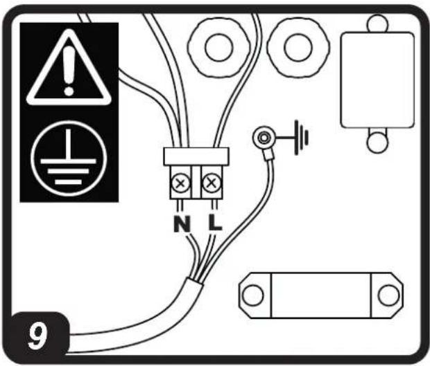
natural_image
Close-up of a mechanical assembly with copper pipe and metal components (no visible text or symbols)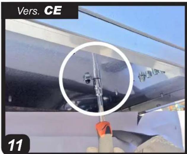
PICTURES - FIGURE - ABBILDUNGEN - FIGURAS - FIGURES - FIGUREN - FIGURAS - FIGURER - KUVAT - FIGURER - FIGURER - ILUSTRACJE - ИЛЛЮСТРАЦИИ - OBRÁZKY - ÁBRÁK - SLIKE - ŞEKİLLER - SLIKE - ILIUSTRACIJOS - ATTĚLI - JOONISED - IMAGINI - OBRÁZKY - CXEMI - МАЛЮНКИ - SLIKE - EIKONEΣ - 图示
natural_image
Close-up of a mechanical assembly with a copper pipe inserted, no visible text or symbols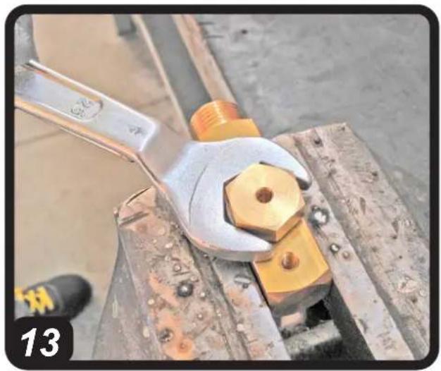
natural_image
Close-up of a hand using a wrench to lift a yellow hexagonal nut on a wooden surface (no text or symbols visible)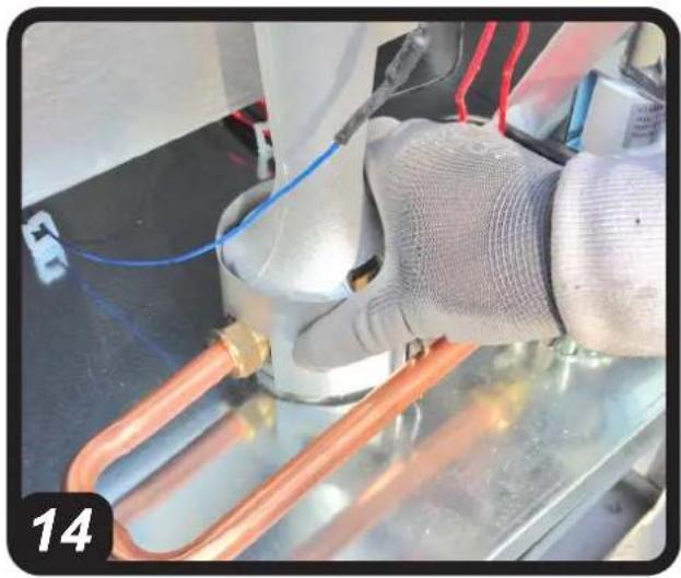
natural_image
Close-up of a hand holding a copper pipe with blue wires and red wires, next to a metallic cylindrical component (no visible text or symbols)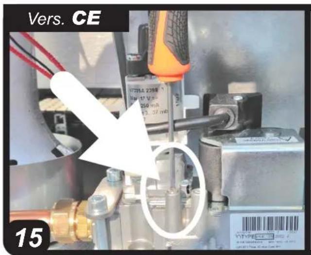
PICTURES - FIGURE - ABBILDUNGEN - FIGURAS - FIGURES - FIGUREN - FIGURAS - FIGURER - KUVAT - FIGURER - FIGURER - ILUSTRACJE - ИЛЛЮСТРАЦИИ - OBRÁZKY - ÁBRÁK - SLIKE - ŞEKİLLER - SLIKE - ILIUSTRACIJOS - ATTĚLI - JOONISED - IMAGINI - OBRÁZKY - CXEMI - МАЛЮНКИ - SLIKE - EIKONEΣ - 图示
PICTURES - FIGURE - ABBILDUNGEN - FIGURAS - FIGURES - FIGUREN - FIGURAS - FIGURER - KUVAT - FIGURER - FIGURER - ILUSTRACJE - ИЛЛЮСТРАЦИИ - OBRÁZKY - ÁBRÁK - SLIKE - ŞEKİLLER - SLIKE - ILIUSTRACIJOS - ATTĚLI - JOONISED - IMAGINI - OBRÁZKY - CXEMI - МАЛЮНКИ - SLIKE - EIKONEΣ - 图示

natural_image
Interior view of an open industrial electrical enclosure with a black plastic component and a lightning bolt symbol (no text or labels visible)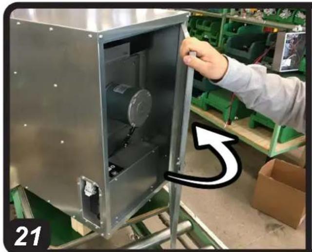
natural_image
Interior view of a stainless steel industrial machine with a hand adjusting its door, surrounded by green storage racks and cardboard boxes (no visible text or symbols)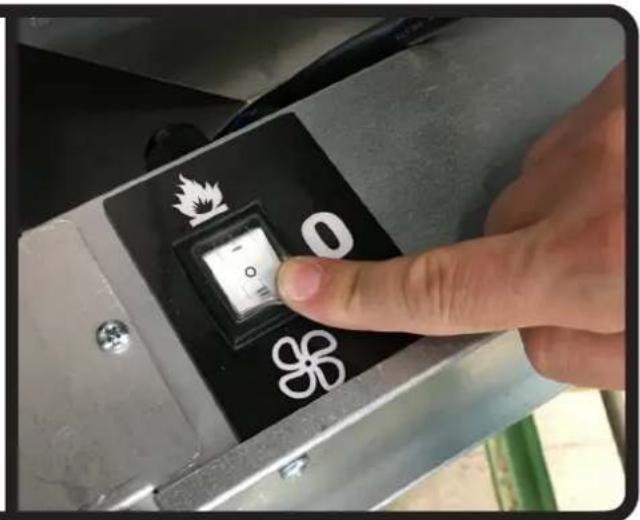
natural_image
Interior view of a stainless steel industrial machine with a hand adjusting its door, surrounded by green storage racks (no visible text or symbols)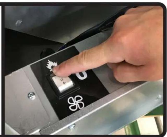
natural_image
Close-up of a hand pressing a black key with white symbols, no readable text or numbers present.PICTURES - FIGURE - ABBILDUNGEN - FIGURAS - FIGURES - FIGUREN - FIGURAS - FIGURER - KUVAT - FIGURER - FIGURER - ILUSTRACJE - ИЛЛЮСТРАЦИИ - OBRÁZKY - ÁBRÁK - SLIKE - ŞEKİLLER - SLIKE - ILIUSTRACIJOS - ATTĚLI - JOONISED - IMAGINI - OBRÁZKY - CXEMI - МАЛЮНКИ - SLIKE - EIKONEΣ - 图示
natural_image
Two-panel image showing a worker installing a metal enclosure and a hand pressing a black control panel with flame and snowflake symbols (no readable text or symbols)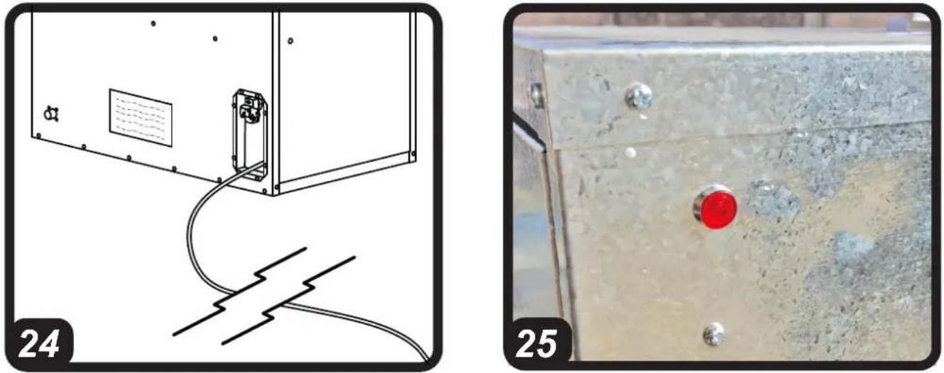
natural_image
Two-panel image showing a device connected to wires and a red circular indicator on a metal panel (no text or symbols present)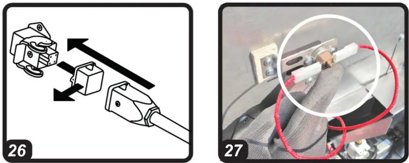
natural_image
Two-panel image showing a mechanical assembly diagram and a close-up of a red rope knot on a device (no text or symbols)PARAGRAPH SUMMARY PARAGRAPH SUMMARY
| 1... DESCRIPTION | |
| 2... WARNINGS | |
| 3... UNPACKING | |
| 4... HANDLING | |
| 5... POSITIONING | |
| 6... CONNECTION TO THE GAS MAINS | |
| 7... CONNECTION TO THE ELECTRICITY MAINS | |
| 8... CONVERSION TO ANOTHER TYPE OF GAS | |
| 9... TYPE OF FUEL | |
| 10... SWITCH-ON | |
| 11... FAULT LIGHT | |
| 12... SWITCH-OFF | |
| 13... CONNECTING THE REMOTE ROOM THERMOSTAT | |
| 14... CLEANING THE HEATER | |
| 15... PUTTING THE HEATER OUT OF SERVICE | |
| 16... OPTIONAL ITEMS | |
| 17... TROUBLESHOOTING |
IMPORTANT: READ AND UNDERSTAND THIS OPERATIONAL MANUAL PRIOR TO ASSEMBLING, STARTING UP OR CONDUCTING MAINTENANCE ON THIS HEATER. USING THE HEATER INCORRECTLY CAN CAUSE SERIOUS INJURY. KEEP THIS MANUAL FOR FURTHER REFERENCE.
▶▶1.DESCRIPTION
THIS PRODUCT HAS BEEN DESIGNED NOT FOR CIVIL - DOMESTIC USE AND COMPLIES WITH THE UNI EN 525:2009 STANDARD. ITS CATEGORY IS A2.
This gas heater is a product that releases heat into the air of the room it operates in by either using natural gas or liquid propane gas. It is intended for fixed installation indoors or outdoors following an assessment of the rooms and by using the designated
kits. The air drawn in by a centrifugal ventilation system is conveyed towards the burner, which controls combustion. This way the air heats up and is introduced into the room again. This direct combustion system mixes the combust-
tion by-products with the air drawn in and releases them into the environment at a later stage. Given that the volume of air treated is greater than the actual combustion needs, hot air comes out with a low concentration of carbon dioxide.
This system means one can create a heater with:
•Maximum thermal efficiency.
- Low thermal inertia.
- Small size and reduced weight.
- Simple design.
•Maximum reliability.
With a specific function, one can activate just activate the ventilation unit, thereby moving around the air.
This product can be identified via the data plate applied on the heater, which perma-
nently reports the gaseous combustible materials that should be used, specifications and all the technical information of the heater. If the data plate or the instruction manual is damaged or lost, please request a duplicate from the authorised technical support centre.
▶▶2.WARNINGS
••2.1.AIMPORTANT: The manufacturer is responsible for compliance of the product with laws, directives or building standards in force when the product is marketed. The technician authorised by the technical support centre and the user are responsible for learning about and complying with the regulations and standards relating to the design of the system, installation, operation and maintenance.
••2.2. IMPORTANT: The manufacturer cannot be held liable for failure to comply with the instructions contained in the following instruction manual, for consequences to any manoeuvre performed and not specifically envisaged or for any translations that may result in erroneous interpretations.
••2.3.AIMPORTANT: This instruction manual is an integral part of the heater and therefore must be carefully preserved. It must always remain with the appliance, even if transferred to another owner or user. If the data plate or the instruction manual is damaged or lost, please request a duplicate from the authorised technical assistance centre.
••2.4. IMPORTANT: This heater is not suitable for use by persons (including children) with reduced physical, sensory or mental capacities or with lack of experience or knowledge unless supervised by a person respon-
sible for their safety. Children must be supervised to make sure they do not play with the heater. Keep animals at a safe distance from the heater.
••2.5. IMPORTANT: Improper use of this heater can cause damage, injuries, burns, explosions, electric shock or endanger life. The first symptoms of suffocation by carbon monoxide are similar to those of flu with headache, light-headedness and/or nausea. These symptoms could be caused by the faulty functioning of the heater. IF THESE SYMPTOMS OCCUR, GO OUTDOORS IMMEDIATELY and have the heater repaired by an authorised technical support centre.
•2.6. IMPORTANT: Any contractual and extra-contractual liability of the manufacturer for injury caused to persons, animals or damage caused to property due to incorrect installation, adjustment and maintenance or improper use is excluded.
••2.7. IMPORTANT: References to laws, regulations, directives and technical rules that may be mentioned in this instruction manual are intended for information purposes only and are believed to be correct at the time of printing of the manual itself. The entry into force of new regulations or amendments to existing ones will not constitute grounds for obligation for the manufacturer towards third parties.
••2.8.AIMPORTANT: The heater must be positioned and secured by qualified personnel. The connection to the gas and electricity mains must be carried out by an authorised technician. When the work is completed, the latter will give the owner the declaration of conformity for the installation performed to a professional standard, i.e.
in compliance with current standards and instructions given by the manufacturer in this instruction manual. Work involving access to dangerous areas (maintenance, repairs, etc.) must be carried out by the authorised technical support centre to prevent any risks.
••2.9. IMPORTANT: The heater does not have gas regulators or pipes to connect it to the mains. Therefore, you will need to contact an authorised technician for the installation.
••2.10.AIMPORTANT: The heater is supplied with a specific gas setting. Any kind of change and adjustment must be performed by an authorised technician or by the authorised technical support centre. IF ANY CHANGES AND ADJUSTMENTS ARE PERFORMED, YOU WILL NEED TO FILL IN THE NEUTRAL DATA PLATE SUPPLIED WITH THE HEATER.
••2.11.AIMPORTANT: The settings of the supply gas pressure values must be checked by an authorised technician.
••2.12. IMPORTANT: The heater must be installed exclusively in accordance with the instructions contained in this instruction manual to prevent any potential fires.
••2.13.AIMPORTANT: Do not use to heat homes or residential buildings; for use in public buildings, refer to national regulations.
••2.14.For correct use of the heater and for preservation of the fuel, follow all local regulations and the Standard in force.
•2.15.If the heater is installed indoors, it needs an adequate supply of fresh air. It must therefore be used in rooms with a guaranteed and continuous supply of fresh air. National Standards in force are valid for installation
and assessment of the supply of fresh air, including the Technical Standards and the provisions regarding accident-prevention and the prevention of fires.
••2.16.The appliance must only be used as a hot air heater (heating mode) or fan (ventilation mode). Follow these instructions scrupulously.
••2.17. Only use fuel, gas pressure values, voltage and electrical frequency clearly specified in the data plate applied on the heater.
••2.18.Make sure the heater is only connected to suitable mains with a differential switch and suitable earthing.
- 2.19.It is prohibited to use the heater in basements and rooms below ground level.
•2.20.The heater must not be used in places where explosive dust, fumes, gases, fuels, solvents, paint, etc. are present.
•2.21. Whenever the heater is used near tarpaulins, awnings or similar covering materials, additional protection is recommended, such as fire-proofing. Make sure the hot parts of the generator are kept at a suitable distance from inflammable materials (fabric, paper, wood, etc.) or thermolabile materials (including the power supply cable). In any case, the distance should never be less than 3 m.
••2.22.The air vent (lower side) and/or the air outlet vent (front side) must not be totally or partially obstructed for any reason You can use air ducting from or to the heater. The only authorised ducting is the one supplied as optional items by the manufacturer.
- 2.23.If the heater does not switch on or switch-on is anomalous, please see the relative section (Paragraph on "Troubleshooting").
••2.24.The heater must never be moved, handled or subjected to any
maintenance interventions when running.
•2.25.Do not open the side inspection doors and carry out work inside when the heater is in operation or when it is powered on and not in operation.
•2.26.If you smell gas, switch the heater off immediately, stop the gas supply, disconnect the heater from the electricity mains, provide fresh air by opening doors and windows and then contact the authorised technical support centre.
••2.27.When the heater is controlled by a remote room thermostat (optional item), the heater can switch back on at any time when the temperature drops below the set threshold.
••2.28.If the heater is not used for an extended period of time, we recommend contacting the authorised technical support centre to put it back in operation.
•2.29.The heater must only be fitted with original accessories. The manufacturer is not responsible for any damage deriving from improper user of the heater and use of non-original materials and accessories.
- 2.30.Do not modify or tamper with the heater as this may lead to hazardous situations. The manufacturer will not be held liable for any damage caused.
-2.31.Do not place any objects on the heater.
-2.32.Do not insert objects through the heater's grids.
- 2.33.Do not touch the air outlet grid, as during normal operation it can reach high temperatures, which may cause serious injury.
- 2.34.Do not use adapters, multi socket outlets and extensions to connect the heater to the electricity mains.
••2.35.Do not perform any cleaning and maintenance before plugging out
the heater from the electricity mains and fuel supply.
••2.36.Ask the technical support service to check that the heater is working properly at least once a year and/or as required.
▶▶3.UNPACKING
DO NOT THROW AWAY THE MATERIALS (CARDBOARD, PLASTIC PACKAGING, BAGS, ETC.) OR GIVE THEM TO CHILDREN OR LEAVE THEM WITH-IN THEIR REACH, AS THEY MAY REPRESENT A HAZARD.
Remove all packaging material used to deliver the heater and dispose of it in compliance with current standards. Check for any damage undergone during transport. If the heater looks damaged, inform the dealer immediately.
▶▶4.HANDLING
THE HEATER MUST BE HANDLED BY QUALIFIED PERSONNEL BY USING SUITABLE DEVICES AND INSTRUMENTS, IN ACCORDANCE WITH NATIONAL REGULATIONS AND CURRENT STANDARDS.
▶4.1. HANDLING THE HEATER WITH THE PACKAGING
It can be lifted with a forklift truck by positioning the supports under the lower base of the packaging.
▶4.2.HANDLING THE HEATER WITHOUT THE PACKAGING
It can be lifted with the forklift truck by positioning the supports underneath the lower base of the packaging or by using chains and suspension hooks.
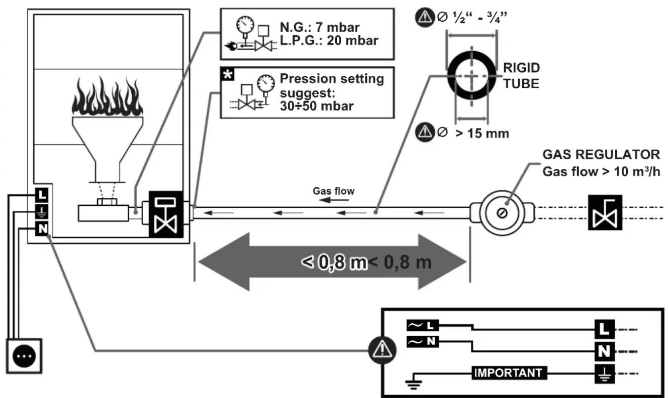
▶▶5.POSITIONING (Fig. 1)
READ THE WARNINGS CAREFULLY AND FOLLOW THE RECOMMENDATIONS CONTAINED IN THIS INSTRUCTION MANUAL BEFORE AND DURING INSTALLATION.
THE HEATER MUST BE POSITIONED BY QUALIFIED PERSONNEL BY USING SUITABLE DEVICES AND INSTRUMENTS, IN ACCORDANCE WITH NATIONAL REGULATIONS AND CURRENT STANDARDS.
- IMPORTANT: Do not power on the heater before the installation has been completed in order to prevent damage to property and/or injury to persons.
This heater is designed to be installed indoors or outside a building. It can be installed outdoors only with the designated original kit (Paragraph on “Optional items”). Before positioning the heater, make sure you have identified the correct position for the installation, away from flammable materials, with the right distance from the ground so as to not obstruct, not even in part, the air intake grid at the bottom of the heater. This is why you need to check the grid is at the right distance from the ground or materials that can be drawn in. The place where it is installed must be easy to access to make normal maintenance and inspection operations easier. The heater must be secured safely and permanently to the structure. Do not attach additional weight to the heater.
▶5.1.INDOOR INSTALLATION ON THE CEILING (Fig. 2-3)
Each chain and suspension hook must withstand a minimum weight of 100 kg. The surface on which the product is attached (for instance the ceiling) must withstand a minimum weight of 200 kg. There must be a positive angle between the chains and a value that can ensure stability, in order to prevent dangerous oscillations.
▶5.2.INSTALLATION ON THE WALL (Fig. 4)
Each wall plug must withstand a minimum load of 200 kg. The masonry structure must withstand the weight of the heater placed on the brackets.
▶5.3.OUTDOOR INSTALLATION ON THE WALL (Fig. 5)
Each wall plug must withstand a minimum load of 200 kg. The masonry structure must withstand the weight of the heater placed on the brackets. The air intake and booster ducts must follow the specifications described in the original kit (Paragraph on “Optional items”).
▶▶6. CONNECTION TO THE GAS MAINS (Fig. 6)
READ THE WARNINGS CAREFULLY AND FOLLOW THE RECOMMENDATIONS CONTAINED IN THIS INSTRUCTION MANUAL BEFORE AND DURING INSTALLATION.
THE GAS SUPPLY LINE AND CONNECTION MUST BE CARRIED OUT BY AN QUALIFIED TECHNICIAN BY USING SUITABLE DEVICES AND INSTRUMENTS, IN ACCORDANCE WITH NATIONAL REGULATIONS AND CURRENT STANDARDS.
The heater is designed to operate with different kinds of gas, but it is supplied with specific factory settings (see data plate applied on the heater). Never exceed the maximum supply pressure values report-
ed on the data plate in order to prevent serious damage to the heater.
The gas regulator must be installed outside the building that needs to be heated and must guarantee a supply at a pressure in line with national regulations and the heater's technical specifications. The regulator can be installed indoors only in a suitably ventilated area. National regulations will help you identify the correct installation.
Connect the heater to the gas mains by placing the utmost attention on the kind of connection (ISO 7-1:1994 thread suitable for sealing on a conical thread). The gas pipes must have a suitable size, position and anchoring. During the ^1 st start-up, use an approved device to check for any leaks due to incorrect tightening or damage to the gas supply circuit.
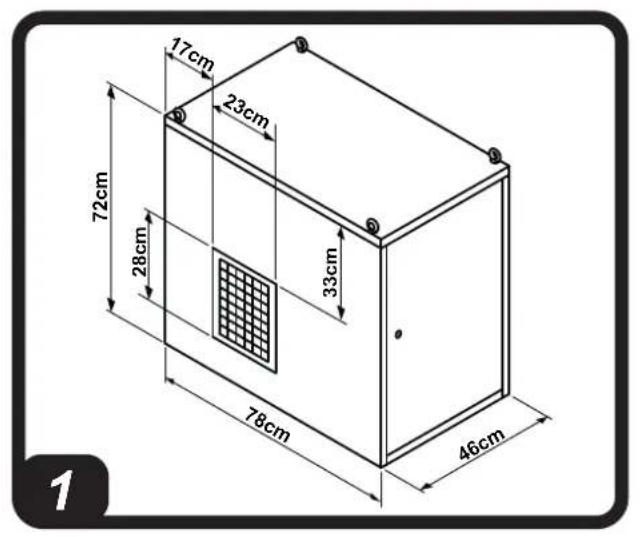
▶▶7. CONNECTION TO THE ELECTRICITY MAINS
READ THE WARNINGS CAREFULLY AND FOLLOW THE RECOMMENDATIONS CONTAINED IN THIS INSTRUCTION MANUAL BEFORE AND DURING INSTALLATION.
THE POWER SUPPLY LINE AND CONNECTION MUST BE CARRIED OUT BY AN QUALIFIED TECHNICIAN BY USING SUITABLE DEVICES AND INSTRUMENTS, IN ACCORDANCE WITH NATIONAL REGULATIONS AND CURRENT STANDARDS.
- IMPORTANT: The heater must be connected to a suitable differential and magnetothermal control system that ensures the power supply is disconnected in the event of any anomalies of the heater. For the correct functioning of the heater, it is
necessary to verify its perfect connection of the grounding.
We recommend using a 1,5 mm ^2 (AWG 16) H07 type cable with length not exceeding 5 m. After making sure the heater is disconnected from the gas mains, open the electrical panel (Fig. 7), insert the supply cable in the cable gland (Fig. 8) and connect the cables to the suitable terminal board (Fig. 9). Upon completing connection restore the electrical panel.
▶▶8.CONVERSION TO ANOTHER
TYPE OF GAS
READ THE WARNINGS CAREFULLY AND FOLLOW THE RECOMMENDATIONS CONTAINED IN THIS INSTRUCTION MANUAL BEFORE AND DURING INSTALLATION.
THE CONVERSION TO ANOTHER TYPE OF GAS MUST BE CARRIED OUT BY AN AUTHORISED TECHNICIAN OR BY THE AUTHORISED TECHNICAL SUPPORT CENTRE BY USING SUITABLE DEVICES AND INSTRUMENTS, IN ACCORDANCE WITH NATIONAL REGULATIONS AND CURRENT STANDARDS.
- IMPORTANT: The conversion must be carried out after closing and disconnecting the heater from the gas and electricity mains (Fig. 24).
The types of gas compatible with this kind of heater are brie y reported in the gas type label. The gas setting, before the conversion of the heater, can be identified based on the data plate applied on the heater. When the gas conversion has been completed, permanently report the parameters of the new setting on the neutral data plate supplied and then apply
it on the heater. Here below are the steps for the conversion to another combustible gas:
▶8.1.REMOVE THE VALVE AND NOZZLE SUPPORT CONNECTION PIPE, REMOVE THE NOZZLE SUPPORT, REMOVE THE NOZZLE PROCEDURE:
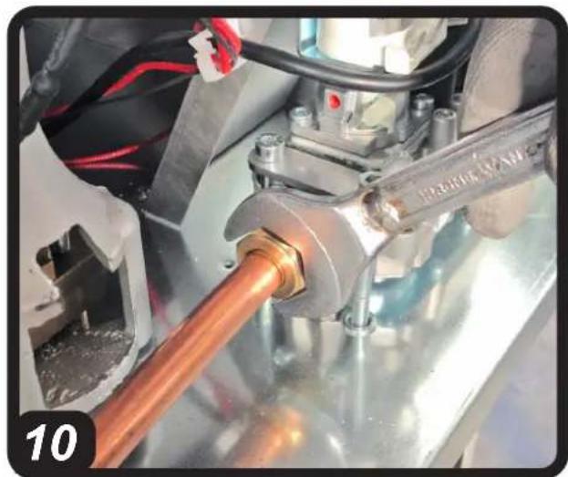
- 8.1.1. Remove the conical tip tightening ring on the valve side (Fig. 10).
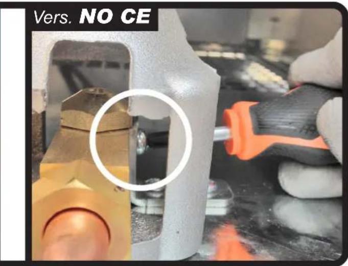
- 8.1.2. Remove the nozzle support fastening screw (Fig. 11).
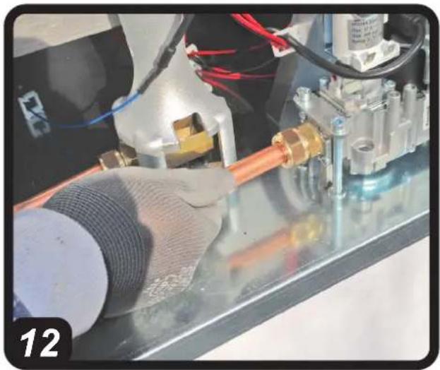
- 8.1.3. Take out the nozzle support and the gas pipe section (Fig. 12).
- 8.1.4. Remove the gas nozzle (Fig. 13). CAUTION: CAREFULLY KEEP ALL THE COMPONENTS (GASKETS, CONICAL TIPS, ETC.).
▶8.2.CHOOSING THE NOZZLE
Choosing the right nozzle:
LPG nozzle = 5 mm diameter
G20 nozzle = 10 mm diameter
G25 nozzle = 10 mm diameter
▶8.3.PLACE BACK THE VALVE AND NOZZLE SUPPORT CONNECTION PIPE, PLACE BACK THE NOZZLE SUPPORT, PLACE BACK THE NOZZLE
PROCEDURE:
- 8.3.1. Attach the nozzle to the nozzle support and ensure the connection is airtight. Make sure the nozzle you choose is suitable for the desired conversion (Fig. 13).
- 8.3.2. Insert the nozzle support with the pipe underneath the burner and secure it to the base with the screw (Fig. 12-11).
- 8.3.3.Tighten the conical tip tightening fitting to the gas valve (Fig. 10).
- 8.3.4. Make sure the connections are firmly attached.
CAUTION: IF USING G20-G25 GAS, INSTALL THE AIR REDUCTION COLLAR (Fig. 14). THIS COLLAR IS ONLY REQUIRED FOR G20-G25 GAS TYPES.
▶8.4.ADJUST THE OUTLET PRESSURE FROM THE GAS VALVE
CAUTION: THE ADJUSTMENT MUST BE CONDUCTED QUICKLY AND ACCURATELY.
After assembling the duct onto the new nozzle, you need to set the heater's multipurpose gas valve at the right supply pressure. The pressure must be adjusted when the heater is in operation and the gas supply is connected. Before starting the adjustment, make sure the heater is powered on with the right type of gas for the nozzle installed.
PROCEDURE:
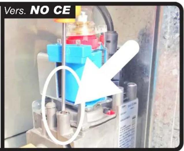
•8.4.1.Identify where the gas valve outlet pressure is taken and remove the tightening screw (Fig. 15).
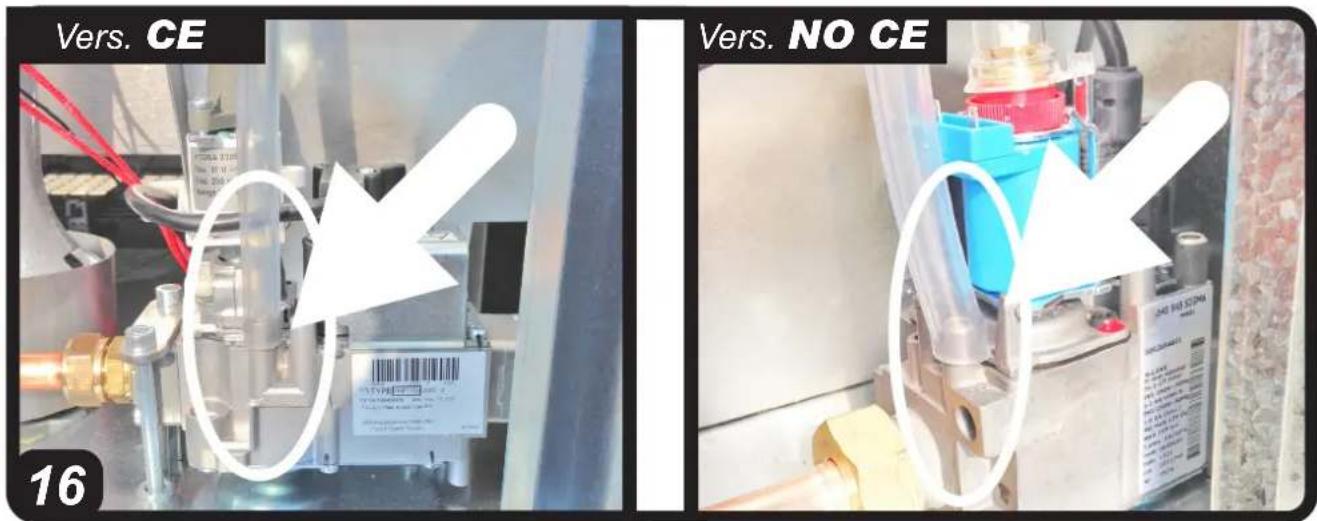
- 8.4.2. Connect a flexible rubber pipe, make sure it is firmly attached (Fig. 16).
Considering that the pressure values are set to minimum values, use a differential manometer or, better still, a water tube manometer.
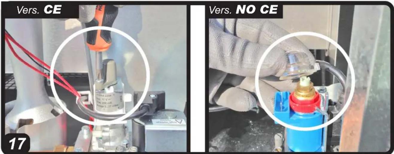
- 8.4.3. Remove the protective cover (Fig. 17) and identify the rotation screw used to adjust the pressure on the gas valve.
- 8.4.4. Prepare the specific tool to operate on the adjustment pin.
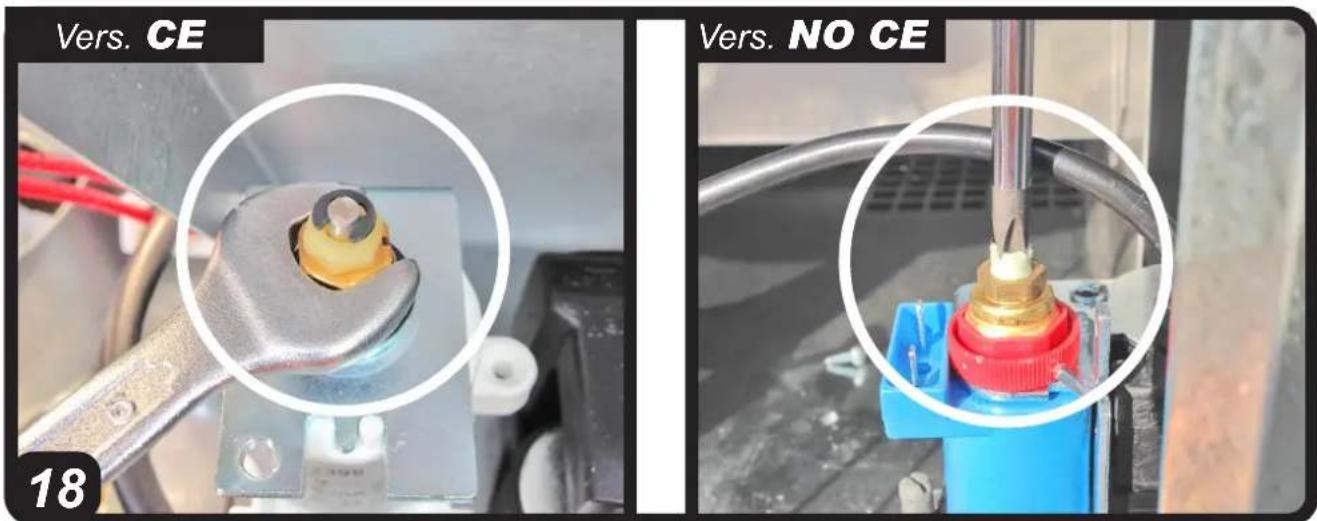
- 8.4.5. Turn on the heater and wait for a few seconds while the prewash is conducted. You can then open the gas and the flame will come on. At this exact moment you need to rotate the pin (Fig. 18) until the required outlet pressure value is reached (clockwise to increase it, anticlockwise to reduce it). After adjusting the pressure, we recommend repeating the ignition cycle three times with the inspection doors closed and by checking again the outlet pressure of the gas valve. Before
completing the gas conversion, you will need to make sure the fittings and gas pipe are firmly attached.
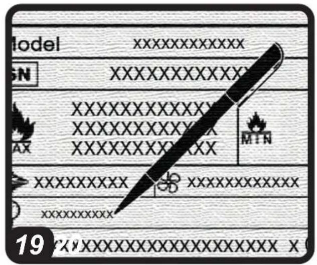
- 8.4.6.When the gas conversion has been completed, permanently report the parameters of the new setting on the neutral data plate supplied (Fig. 19) and then apply it on the heater.
▶▶9.TYPE OF FUEL
ONLY USE GAS RELATING TO THE CATEGORY REPORTED ON THE GAS TYPE STICKER TO PREVENT SERIOUS DAMAGE TO THE HEATER.
▶▶10.IGNITION (Instructions for ignition, ventilation and heating) (Fig. 20)
READ THE WARNINGS CAREFULLY AND FOLLOW THE RECOMMENDATIONS CONTAINED IN THIS INSTRUCTION MANUAL WHEN USING THE PRODUCT.
THE FIRST START-UP MUST BE CON- DUCTED BY AN AUTHORISED TECH- NICIAN OR BY THE AUTHORISED TECHNICAL SUPPORT CENTRE.
- IMPORTANT: Before the first ignition, make sure there are no packaging residues or accessories inside the heater.
- IMPORTANT: Before turning on the product, make sure the heater is installed correctly (the gas connection, inlet pressure and electrical connection must comply with current regulations and match the values declared on the data plate). Also ensure there are no obstructions in the air circuit.
- IMPORTANT: During the first start-up, use an approved device to check for any leaks due to incorrect tightening or damage to the gas supply circuit.
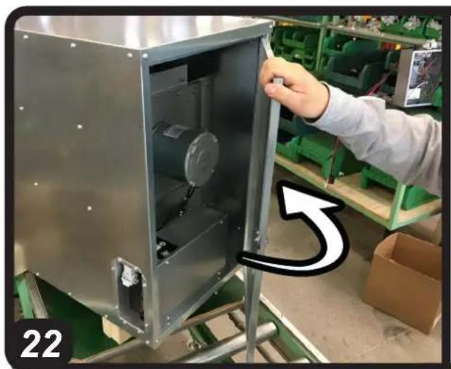
The heater can operate either in ventilation or heating mode. To start the ventilating mode, set the button to the "FAN" position (Fig. 21). This way the heater only starts the motor and keeps the gas circuit closed. If you want to start the heating mode, set the button to the "FLAME" position (Fig. 22). The heater opens the gas circuit and starts the spark - thereby starting the combustion - only after activating just the fan to ensure the prewash of the combustion chamber for around 30 seconds.
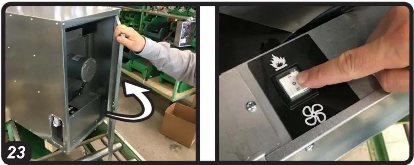
If the ignition fails more than 3 times, the heater is blocked. To reset the heater, set the start button to "O" (Fig. 23). A preventive analysis of potential causes is briefly reported in the anomalies table (Paragraph on "Troubleshooting").
CAUTION: IF THE IGNITION FAILS MORE THAN THREE TIMES, THE REASON NEEDS TO THE CHECKED VIA THE AUTHORISED TECHNICAL SUPPORT CENTRE.
▶▶11.WARNING LIGHT
The heater is fitted with a light to monitor the heater's operation (Fig. 25):
- LIGHT OFF (normal condition): This means the heater is off or working normally.
- LIGHT ON: This means the heater is blocked.
▶▶12.TURNING OFF THE HEATER
To turn off the heater, set the button to the "O" position (Fig. 23).
CAUTION: WHEN THE PUSHBUTTON IS IN POSITION "O", THE HEATER IS OFF BUT IS STILL POWERED BY THE MAINS POWER NETWORK. FOR MAINTENANCE, CLEANING OR OTHER IT IS
REQUIRED TO COMPLETELY ISOLATE THE HEATER FROM THE MAINS POWER NETWORK (Fig. 24).
▶▶13.CONNECTING THE REMOTE ROOM THERMOSTAT
- IMPORTANT: When the heater is controlled by a remote room thermostat, the heater can switch back on at any time when the temperature drops below the set threshold.
To connect the remote room thermostat, remove the plug connected to the heater and connect the remote room thermostat (optional item) (Fig. 26).
▶▶14.CLEANING THE HEATER
- IMPORTANT: Do not conduct any cleaning unless the heater has first been turned off (Fig. 23) and disconnected from the mains (Fig. 24).
The only possible cleaning steps carried out by the user are associated with the heater's outer surfaces. Only use a damp, non-abrasive cloth to clean the outer surface of the heater (do not use sponges with aggressive products or powder detergents). After cleaning the surface, dry it thoroughly.
CAUTION: IF THE HEATER NEEDS MORE THOROUGH CLEANING, CONTACT THE AUTHORISED TECHNICAL SUPPORT CENTRE.
▶▶15.PUTTING THE HEATER OUT OF SERVICE
If the heater is not used on the medium/long term, disconnected it from the electricity mains (Fig. 24) and protect it from humidity and dust. When the heater is used again, check the condition of the power supply cable. If in doubt regarding its state, contact the technical support centre. In any case, have the heater checked once a year.
▶▶16.OPTIONAL ITEMS
- Outdoor assembly kit (recirculation or air suction mode, depending on the external damper position).
- Remote room thermostat.
•Air outlet opening diffuser.
▶▶17.TROUBLESHOOTING
| FAULTS CAUSES SOLUTIONS | ||
| The heater doesn't work | No voltage 1.Check the | mains system2.Check the electrical connections3.Authorised technical support centre |
| Incorrect connection of the room thermostat | 1.Connect the room thermostat correctly | |
| The heater doesn't work in heating mode | Tripped room thermostat (optional item) | 1.Set the room thermostat at a temperature lower than the room thermostat |
| Incorrect connection of the room thermostat | 1.Connect the room thermostat correctly | |
| Room thermostat socket cap not inserted properly | 1.Insert the cap properly in the socket | |
| No gas supply 1.Check | the gas system2.Authorised technical support centre | |
| Blocked heater 1.Reset | the heater by setting the power button to position “0”2.Authorised technical support centre | |
| Defective electronic equipment | 1.Authorised technical support centre | |
| Incorrect heater setting | 1.Authorised technical support centre | |
| The flame does not stay on | Defective electronic equipment | 1.Authorised technical support centre |
| The flame turns off during normal operation | Tripped room thermostat (optional item) | 1.Set the room thermostat at a temperature lower than the room thermostat |
| No gas supply 1.Check | the gas system2.Authorised technical support centre | |
| No voltage 1.Check the | mains system2.Check the electrical connections3.Authorised technical support centre | |
| The heater overheats 1. | Clean the air inlet (lower side) and reset the manual security thermostat (Fig. 27)2.The heater's limit operating temperatures are too high3.The air intake temperatures are too high4.Extensive exposure to sun light5.Authorised technical support centre | |
SOMMARIO PARAGRAFI SOMMARIO PARAGRAFI
| 1... DESCRIZIONE |
| 2... AVVERTENZE |
| 3... DISIMBALLAGGIO |
| 4... MOVIMENTAZIONE |
| 5... POSIZIONAMENTO |
| 6... COLLEGAMENTO ALLA RETE GAS |
| 7... COLLEGAMENTO ALLA RETE ELETTRICA |
| 8... CONVERSIONE AD ALTRO TIPO DI GAS |
| 9... TIPO DI COMBUSTIBILE |
| 10... ACCENSIONE |
| 11... DIAGNOSI SPIA |
| 12... SPEGNIMENTO |
| 13... COLLEGAMENTO TERMOSTATO AMBIENTE REMOTO |
| 14... PULIZIA DEL RISCALDATORE |
| 15... MESSA FUORI SERVIZIO DEL RISCALDATORE |
| 16... OPTIONAL |
| 17... ANOMALIE, CAUSE E RIMEDI |
IMPORTANTE: LEGGERE E COMPRENDERE QUESTO MANUALE OPERATIVO PRIMA DI EFFETTUARE L'ASSEMBLAGGIO, LA MESSA IN FUNZIONE O LA MANUTENZIONE DI QUESTO RISCALDATORE. L'USO ERRATO DEL RISCALDATORE PUÒ CAUSARE LESIONI GRAVI. CONSERVARE QUESTO MANUALE A TITOLO DI FUTURO RIFERIMENTO.
▶▶1.DESCrizIONE
▶▶17.ANOMALIE, CAUSE E RIMEDI
▶ 5.1.DECKENINSTALLATION INNEN (Abb. 2-3)
▶5.2.WANDINSTALLATION INNEN (Abb. 4)
▶▶17.PROBLEMAS, CAUSAS Y SOLUCIONES
▶▶5.MISE EN PLACE (Fig. 1)
LIRE ATTENTIVEMENT LES AVERTISSEMENTS ET SUIVRE LES CONSIGNES CONTENUES DANS CE MANUEL D'INSTRUCTIONS AVANT ET PENDANT L'INSTALLATION.
LA MISE EN PLACE DE L'APPAREIL DE CHAUFFAGE DOIT ÊTRE EFFECTUÉE PAR UN PERSONNEL QUALIFIÉ, EN UTILISANT DES DISPOSITIFS ET DES INSTRUMENTS APPROPRIÉS, CONFORMÉMENT À LA RÈGLEMENTATION NATIONALE ET AUX NORMES EN VIGUEUR.
▶▶6.RACCORDEMENT AU RÉSEAU DE GAZ (Fig. 6)
LIRE ATTENTIVEMENT LES AVERTISSEMENTS ET SUIVRE LES CONSIGNES
CONTENUES DANS CE MANUEL D'INSTRUCTIONS AVANT ET PENDANT L'INSTALLATION.
LA RÉALISATION DE LA LIGNE D'ALIMENTATION DU GAZ ET DU RACCORDEMENT DOIT ÊTRE EFFECTUÉE PAR UN TECHNICIEN HABILITÉ EN UTILISANT DES DISPOSITIFS ET DES INSTRUMENTS APPROPRIÉS, CONFORMÉMENT À LA RÈGLEMENTATION NATIONALE ET AUX NORMES EN VIGUEUR.
▶▶9.TYPE DE COMBUSTIBLE
N'UTILISER QUE DU GAZ DE LA CATÉGORIE INDIQUÉE SUR L'ADHÉSIF DES TYPES DE GAZ AFIN D'ÉVITER DE GRAVES DOMMAGES À L'APPAREIL DE CHAUFFAGE.
▶▶17.ANOMALIES, CAUSES ET SOLUTIONS
▶▶5.USTAWIANIE (Rys. 1)
▶5.2.INSTALACJA WEWNĄTRZ, NAŚCIENNA (Rys. 4)
▶5.3.INSTALACJA NA ZEWNĄTRZ, NAŚCIENNA (Rys. 5)
▶▶8.KONWERSJA NA INNY RODZAJU GAZU
▶▶14.CZYSZCZENIE NAGRZEWNI-CY
Stefano Verani (Member of the Board)
NOTE:
▶en - LIMITED WARRANTY AND AFTER-SALES SERVICE KEEP THIS LIMITED WARRANTY
During the period of twelve (12) months starting from the date of purchase of this product, the manufacturer guarantees that the appliance, all of its parts, do not have flaws due to manufacturing or the materials used, as long as the appliance has been used following the instructions and maintenance indicated in the manual. This warranty is only valid for the original purchaser of the appliance, which must present the purchase invoice. This warranty only includes the cost of the parts necessary to return the appliance to its normal functioning state. Therefore, costs relative to transport or other material associated with the parts covered by this warranty are excluded. The faults produced by incorrect use, manipulation, negligence, insufficient maintenance, alterations, modifications, normal wear of the product are not covered by this warranty, as also the use of non-compliant fuel, repairs using non-original spare parts or repairs performed by staff not working for the dealer or the authorised technical after-sales service. Routine maintenance is the owner's responsibility. The manufacturer does not guarantee, nor is directly or indirectly responsible, for any other warranty including that of a commercial nature or for appropriation for a particular use. In no case is the manufacturer liable for direct, indirect, accidental or consequent damage, deriving from use of the appliance. The manufacturer reserves the right to modify this warranty at any time and without forewarning. This is the only valid warranty. The manufacturer does not assume any expressed or implicit warranty.
▶it - GARANZIA LIMITATA E SERVIZIO ASSISTENZA SERVICE CONSERVARE LA PRESENTE GARANZIA LIMITATA
Date of Purchase: ____
▶en - DISPOSAL OF THE PRODUCT
-This product has been designed and manufactured with top-quality materials and components, which can be re-cycled and re-used. -When a crossed-wheely bin symbol is attached to the product, it means that the product is protected by the, 2012/19/UE European Directive.
-Please obtain information regarding the local differentiated collection system for electrical and electronic products.
-Respect local Standards in force and do not dispose of old products as normal domestic waste. Correct disposal of the product helps to prevent possible negative consequences for health, the environment and mankind.
▶ Iv - PRODUKTA IZNÍCINÁŠANA
natural_image
Abstract geometric composition with yellow and black blocks (no text or symbols)Dantherm S.p.A.
Via Gardesana 11
37010 Pastrengo (VR)
Italy
t.: +39 045 6770533
e.: info.it@danthermgroup.com

DOWNLOAD CATALOGUE

SEND US YOUR FEEDBACK

REGISTER FOR 3-YEARWARRANTEE