
ELVOX EAM6.N - Gate automation Vimar - Free user manual and instructions
Find the device manual for free ELVOX EAM6.N Vimar in PDF.

| Product type | Articulated actuator for swing gates (SLAVE 24 V - manual also mentions model EKKO ART 200D) |
| Brand | Vimar / Elvox |
| Model | ELVOX EAM6.N (actuator EKKO ART 200D) |
| Use | Swing gates up to 2 m per leaf |
| Max leaf weight | 200 kg |
| Max torque | 150 Nm |
| Average opening time | 17 seconds |
| Power supply | 230 V~ 50 Hz |
| Motor power | 72 W |
| Current absorption | 0.311 A |
| Protection rating | IP44 |
| Operating temperature | -30 °C to +55 °C |
| Noise level | < 70 dB |
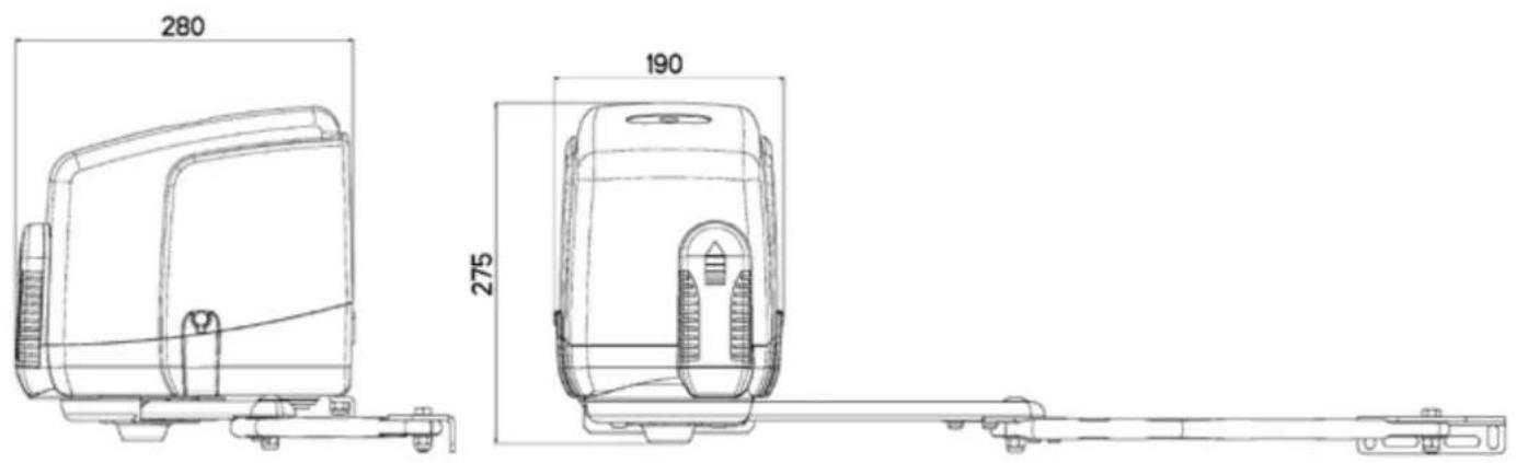
| Dimensions (L x H x W) | Approx. 280 x 275 x 190 mm |
| Motor weight | 7.5 kg |
| Recommended cycles per day | 60 cycles |
| Emergency release | By key (180°) or external safe (code EDP4) |
| Safety features | Anti-intrusion lock, mechanical limit stops, obstacle detection via control unit |
| Maintenance | Grease hinges every 6 months; check impact forces according to EN12453 |
| Standards | Compliant with LVD, EMC, R&TTE, Machinery Directives (2006/42/EC) |
Frequently Asked Questions - ELVOX EAM6.N Vimar
User questions about ELVOX EAM6.N Vimar
0 question about this device. Answer the ones you know or ask your own.
Ask a new question about this device
Download the instructions for your Gate automation in PDF format for free! Find your manual ELVOX EAM6.N - Vimar and take your electronic device back in hand. On this page are published all the documents necessary for the use of your device. ELVOX EAM6.N by Vimar.
USER MANUAL ELVOX EAM6.N Vimar
natural_image
Exterior view of a modern office building (no signage)EAM6.N
natural_image
Close-up of a hand inserting a small electronic component into a device (no visible text or symbols)
natural_image
Technical line drawing of a mechanical assembly with labeled component B (no text or symbols beyond label)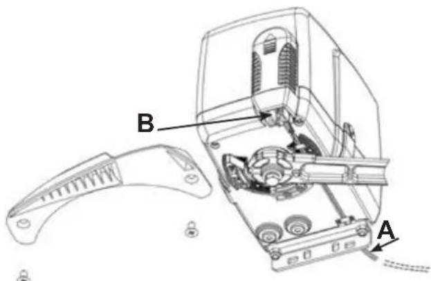
natural_image
Exterior view of a white electronic device labeled 'C' with a small key and lock nearby (no readable text or symbols beyond label)3
FISSAGGIO ATTACCO MOTORE A COLONNA (D)
natural_image
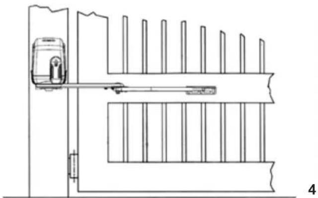
Technical line drawing of a door frame with vertical supports and a mounted device (no text or symbols)MONTAGGIO LEVE DI TRAINO CON DISPOSITIVO DI BLOCCAGGIO ANTI-INTRUSIONE (E)
natural_image
Close-up of a mechanical component with metallic joints and bolts (no visible text or symbols)6
natural_image
Technical line drawing of a mechanical assembly with exploded view and disassembled component (no text or symbols)7
REGOLAZIONE FINECORSA MECCANICI
natural_image
Black mechanical lever handle with curved arm and side clip (no text or symbols)natural_image
Exterior view of a KORET device with two keys beside it (no text or symbols visible on the device body)IMPORTANT SAFETY INSTRUCTIONS
FOR THE INSTALLATION
ATTENTION
FOR THE SAFETY OF THE PEOPLE IT IS IMPORTANT TO FOLLOW ALL THE INSTRUCTIONS.
FOLLOW ALL INSTALLATION INSTRUCTIONS
1° - This handbook is exclusively addressed to the specialized personnel who knows the constructive criteria and the protection devices against the accidents for motorized gates, doors and main doors (follow the standards and the laws in force).
2° - The installer will have to issue to the final user a handbook in accordance with the EN 12635.
3° - Before proceeding with the installation, the installer must forecast the risks analysis of the final automatized closing and the safety of the identified dangerous points (following the standards EN 12453/EN 12445).
4° - The wiring harness of the different electric components external to the operator (for example photoelectric cells, flashlights etc.) must be carried out according to the EN 60204-1 and the modifications to it done in the point 5.2.2 of the EN 12453.
5^ - The possible assembly of a keyboard for the manual control of the movement must be done by positioning the keyboard so that the person operating it does not find himself in a dangerous position; moreover, the risk of accidental activation of the buttons must be reduced.
6° - Keep the automatism controls (push-button panel, remote control etc.) out of the children way. The controls must be placed at a minimum height of 1,5 m from the ground and outside the range of the mobile parts.
7° - Before carrying out any installation, regulation or maintenance operation of the system, take off the voltage by operating on the special magnetothermic switch connected upstream it.
THE ELVOX COMPANY DOES NOT ACCEPT ANY RESPONSIBILITY for possible damages caused by the non observance during the installation of the safety standards and of the laws in force at present.
KEEP THESE INSTRUCTIONS WITH CARE
1° - Install a thermal magnetic switch (omnipolar, with a minimum contact opening of 3 mm) before the control board, in case this is not provided with it. The switch shall be guaranteed by a mark of compliance with international standards. Such a device must be protected against accidental closing (e.g. Installing it inside the control panel key locked container).
2° - As far as the cable section and the cable kind are concerned, ELVOX suggests to use an H05RN-F cable, with a minimum section of 1.5mm², and to follow, In any case, the IEC 364 standard and Installation regulations In force In your Country.
3^ - Positioning of an eventual pair of photocells: The beam of the photocells must be at an height not above the 70~cm from the ground, and, should not be more than 20~cm away from the axis of operation of the gate (Sliding track for sliding gate or door, and the hinges for the swing gate). In accordance with the point 7.2.1 of EN 12445 their correct functioning must be checked once the whole installation has been completed.
4^ - In order to comply with the limits defined by the EN 12453 norm, if the peak force is higher than the limit of 400N set by the norm, it is necessary to use an active obstacle detection system on the whole height of the gate (up to a maximum of 2,5m ) - The photocells in this case must be apply externally between the columns and internally for all the race of the mobil part every 60 ÷ 70~cm for all the height of the column of the gate up to a maximum of 2,5m (EN 12445 point 7.3.2.1). example: column height 2,2m 6 copies of photocells - 3 internal and 3 external.
N.B.: The system must be grounded
Data described by this manual are only Indicative and ELVOX reserves to modify them at any time. Install the system complying with current standards and regulations.
Directive 2002/96/EC (WEEE)
The crossed-out wheelie bin symbol marked on the product indicates that at the end of its useful life, the product must be handled separately from household refuse and must therefore be assigned to a differentiated collection centre for electrical and electronic equipment or returned to the dealer upon purchase of a new, equivalent item of equipment.
The user is responsible for assigning the equipment, at the end of its life, to the appropriate collection facilities.
Suitable differentiated collection, for the purpose of subsequent recycling of decommissioned equipment and environmentally compatible treatment and disposal, helps prevent potential negative effects on health and the environment and promotes the recycling of the materials of which the product is made. For further details regarding the collection systems available, contact your local waste disposal service or the shop from which the equipment was purchased.

Risks connected to substances considered as dangerous (WEEE).
According to the WEEE Directive, substances since long usually used on electric and electronic appliances are considered dangerous for people and the environment. The adequate differentiated collection for the subsequent dispatch of the appliance for the recycling, treatment and dismantling (compatible with the environment) help to avoid possible negative effects on the environment and health and promote the recycling of material with which the product is compound.
SYSTEM LAY-OUT
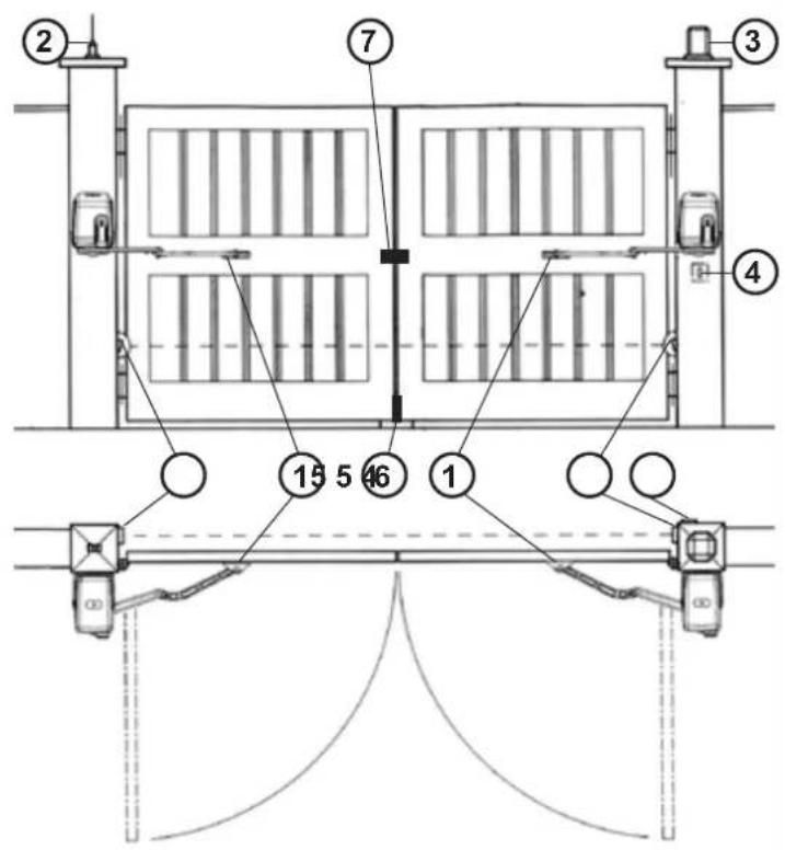
1 - EKKO ART 200D operator
2 - Tuned aerial
3 - Flashing lamp
4 - Key selector
5 - Photoelectric cells (external)
6 - Safety lock
7 - Electrical lock
1
TECHNICAL FEATURES
EKKO ART 200D is an irreversible actuator designed for swing gates long up to 2 m (Pic. 1).
EKKO ART 200D works without electric limit switches, but with mechanical stoppers.
A few seconds after that the gate leaf reaches the end of the stoke, either a time or a current sensor device, will cut out the motor (power supply).
| TECHNICAL DATA | EKKO ART 200D |
| Max. gate leaf length | m. 2 |
| Max. gate leaf weight | kg 200 |
| Average opening time | s. 17 |
| Maximum thrust torque | Nm 150 |
| EEC Power supply | 230 V~ 50 Hz |
| Motor power | W 72 |
| Absorbed current | A 0,311 |
| Daily operations suggested | n° 60 |
| Service | 80 % |
| Guaranteed consecutive cycles | n° 60 - 17 s |
| Actuator weight | kg 7,5 |
| Noise | db <70 |
| Volume | m3 0,0184 |
| Operating temperature | °C -30 ÷ +55 °C |
| Protection grade | IP 44 |
INSTALLATION EKKO ART 200D
PRE-INSTALLATION CHECK LIST
The gate leaves must be firmly fixed to the hinges on the gate pillars, they must not flex during the movement and they must swing without any friction. Before installing the operator, make sure you have enough room to fix the operator on the pillar.
In case the gate is like the one depicted in Pic. 1, there is no need for any modification.
Gate features and installation must comply with local regulations and standards.
The gate can be automated only if it is in good conditions and complies with EN12604 norms.
- The gate leaf must not have a pedestrian door in its structure. Should there be a pedestrian opening, take the appropriate steps according to EN12435 norms (e.g. cutting out the motor when the pedestrian door is opened by fixing a safety micro switch connected to the control board).
- Make sure not to create any trapping points or areas (e.g. when the gate completely opened, between any opening in the gate frame and the side wall).
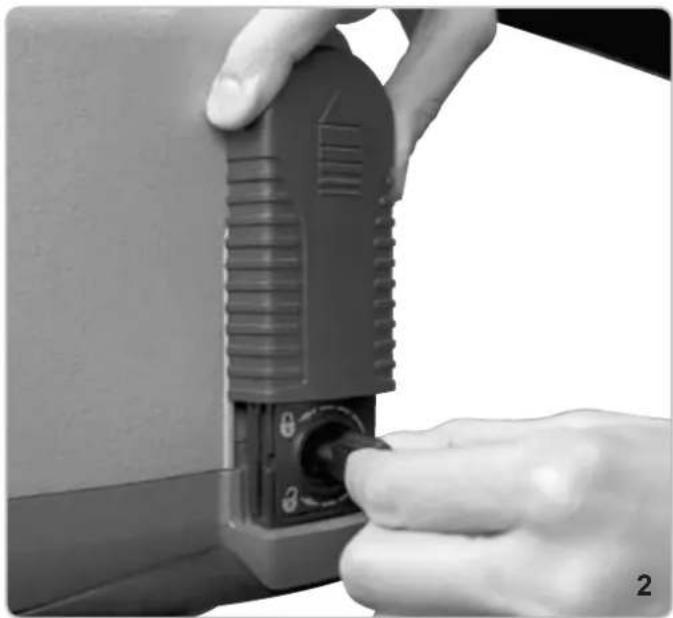
EMERGENCY MANUAL RELEASE
This applies only if the unit is not equipped with back-up batteries. In case of a black-out, the gate can be pulled open after the operator has been unlocked with the emergency key provided (rotate the key clockwise by 180°, Pic. 2).
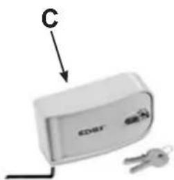
EMERGENCY MANUAL RELEASE THROUGH AN EXTERNAL STRONG BOX
In case of a black-out, should you need to unlock the gate from outside through an external Strong Box, secure one end of the steel cord with sheath (A) to the unlocking lever (B) on the operator, and the other end to the unlocking device (C) inside the strong box, as in Pic. 3 (code EDP4).
CAUTION
In order to manually open the gate leaf make sure of the following:
- The gate leaves must be endowed with appropriate handles;
- Position of the handles onto the gate leaves must be in risk free area;
- The manual force necessary to move the gate leaves should not be higher than 225 N, in case of installations at domestic/private dwellings, and 390 N in case of installations in business premises (according to points 5.3.5 of the EN12453 norm).
Note: in case of an installation with an overlapping two leave swing gate, to ensure a safe/proper locking, a mechanical bolt must be installed along with an electric lock. The mechanical bolt (ZD26) must be installed at the bottom of the first gate leaf to close so that it will be trigger by the pressure of the second gate leaf. The electric lock will latch one gate leaf to the other.
Parts to install to comply with EN 12453 standard
| COMMAND TYPE | USE OF THE SHUTTER | ||
| Skilled persons Skilled (out of public area) (public area) | Unrestricted use | ||
| with manned operation | A B not possible | ||
| with visible impulses (e.g. sensor) | or E C or E C and D, or E | ||
| with not visible impulses (e.g. remote controldevice) | C or E | C and D, or E | C and D, or E |
| automatic | C and D, or E | C and D, or E | C and D, or E |
A: Command button with manned operation.
B: Key selector with manned operation, (gate operating as long as the button is held pressed) like code EDS1.
C: Adjustable power of the motor.
D: Safety edges ZX01/EN to keep thrust force within the limits of EN12453 regulation - Appendix A.
E: Photocells, like code EFA1 (to install every 60-70cm from top to bottom of the gate, to a maximum of 2.5m - EN12445 point 7.3.2.1).
natural_image
Close-up of a hand inserting a small electronic device into a button (no visible text or symbols)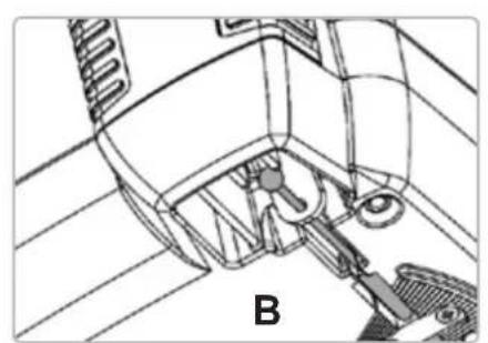
natural_image
Technical line drawing of a mechanical assembly with labeled component B (no text or symbols present)
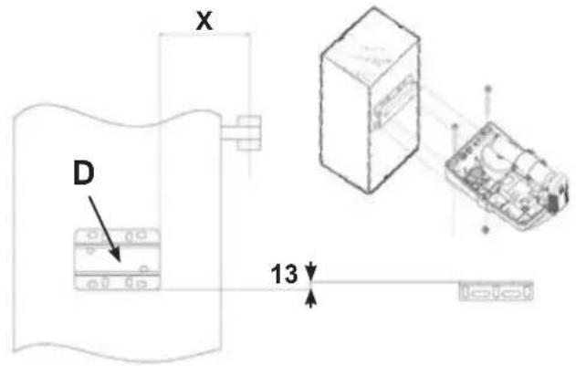
FIXING THE OPERATOR TO THE PILLAR (D)
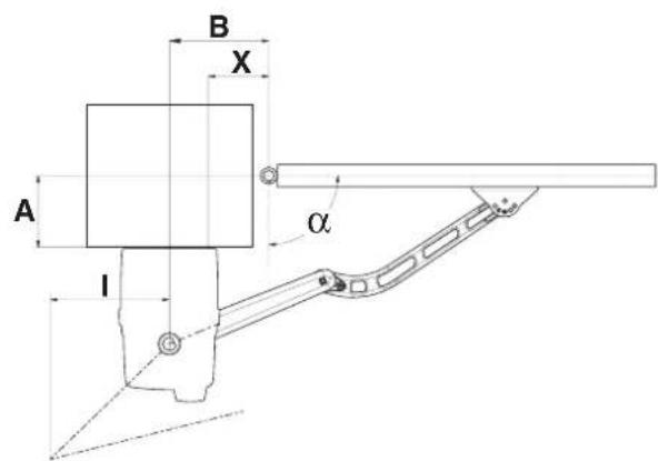
In order to carry out a proper installation of the operator, it is necessary to comply with the geometry measurement shown in the tables in Pic. 6 and 8.
natural_image
Technical line drawing of a door frame with vertical supports and a front-mounted device (no text or symbols)ASSEMBLING DRIVE ARM WITH THE ANTI-THEFT LOCKING DEVICE (E)
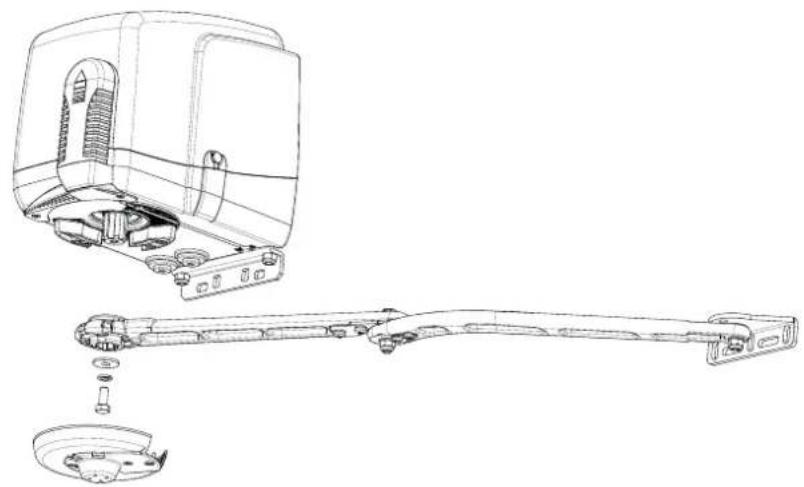
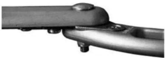
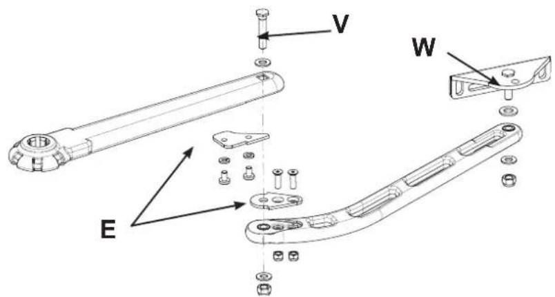
Assemble the arms as shown in Pic. 5.
Caution: Once the screws V and W have been thoroughly tightened (Pic. 5) unscrew them for half a turn, in order to guarantee a free movement of the arm.
After assembling the arm, unlock the motor and fix the arm to the motor with the supplied screw and M10 washer.
natural_image
Close-up of a metallic mechanical component with bolts and a curved handle (no visible text or symbols)With the gate in closing position and the motor at rest, the anti-theft lock (E) keeps the gate leaves securely closed and prevents anybody from forcing the gate leaves open.
5
FIXING THE DRIVE ARM WITH THE ANTI-THEFT LOCKING DEVICE (E)
Unlock the operator.
Caution: start the operation with the gate in closing position. Straighten the levers until the anti-theft lock (E Pic. 5) is engaged and stressed. Move the levers back a little bit just enough to avoid keeping the anti-theft locking in working position (stressed) every time the gate will close.
| ^ | A max | A max* | X | B | I | T sec |
| 90 140 190 | 60 130 | 300 | 20 | |||
| 90 200 200 | 70 140 | 270 | 19 | |||
| 90 205 205 | 80 150 | 230 | 18 | |||
| 90 225 225 | 90 160 | 135 | 16 | |||
| 90 - | 240 110 | 180 0 | 15 | |||
| 95 0 | 0 | 70 140 | 284 | 18 | ||
| 100 0 | 0 90 | 160 302 | 19 | |||
| 105 0 | 0 110 | 180 315 | 19 | |||
| 110 0 | 0 155 | 225 322 | 19 |
A max * - When using only one opening stop (Fig. 8)
6
natural_image
Technical line drawing of a mechanical assembly showing internal components and exploded view (no text or labels)7
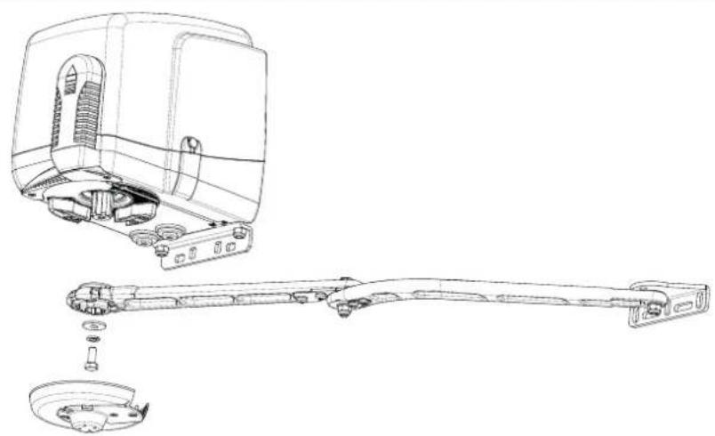
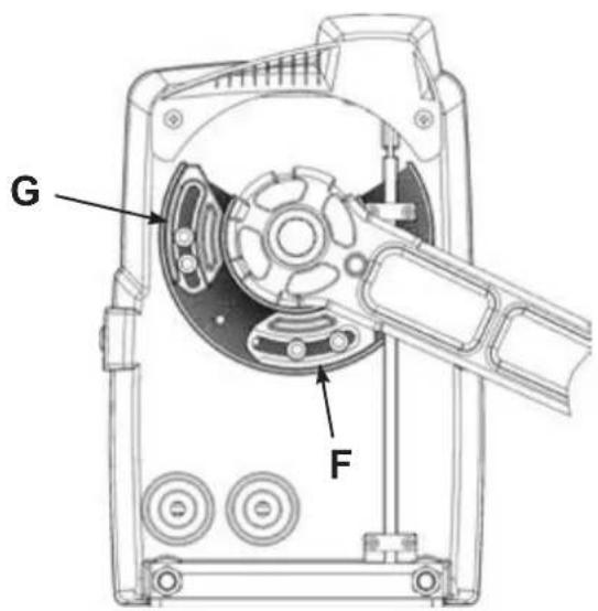
ADJUSTMENT OF THE MECHANICAL STOPPERS
Adjust the mechanical stoppers as shown in Pic. 8.
When the gate is completely closed, slide the close mechanical stopper (F) against the arm. Then tighten it (key n. 5) with the two Allen screws 6x20 provided. In case an electric lock is fitted on the gate, the close mechanical stopper must be removed.
To adjust opening position, slide the open mechanical stopper (G) against the arm (gate must be opened completely) and tighten it as described above.
Caution: Always use two Allen screws for every stopper.
Caution: The drive arm is equipped with an anti-theft locking device (E in Pic. 5). If the close mechanical stopper is not properly adjusted the anti-theft device can get damaged in a short period.
MAINTENANCE
Maintenance should be carried out by skilled and qualified staff only, after switching off the mains supply.
Regularly lubricate the hinges of the gate every 6 months and keep the force monitored (according to EN12453).
8
ACCESSORIES - For the connections and the technical data of the optional equipments follow the relevant handbooks.
LONG LEVER

natural_image
Black mechanical lever handle with curved arm and side clip (no text or symbols)The long lever is suggested for a leaf with a distance up to 500 mm between the hinge of the leaf and the internal side of the pillar.
code EAX2
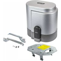
STRONG BOX FLAT

natural_image
Exterior view of a white electronic device labeled 'EDAY' with two keys beside it (no additional text or symbols visible)It is a strong metal (die-cast aluminium) container with lock to protect manual release and/or push button. It is provided with a rocker switch and unlocking device. It has to be fitted onto the wall.
In die-cast aluminium - IP54
code EDP4
EC DECLARATION OF CONFORMITY
(Declaration of incorporation of partly completed machinery annex IIB Directive 2006/42/EC)
No.: ZDT00447.00
The undersigned, representing the following manufacturer
Elvox SpA
Via Pontarola, 14/a
35011 Campodarsego (PD) Italy
herewith declares that the products
ACTUATORS FOR GATES WITH SWING DOORS - SERIES EKKO ART
Articles
EKKO ART 200D
are in conformity with the provisions of the following EC directive(s) (including all applicable amendments) and that the following standards and/or technical specifications have been applied:
LV Directive 2006/95/EC: EN 60335-2-103 (2003) + A11 (2009)
EMC Directive 2004/108/EC: EN 61000-6-1 (2007), EN 61000-6-3 (2007) + A1 (2011),
EN 61000-6-2 (2005), EN 61000-6-4 (2007) + A1 (2011)
R&TTE Directive 1999/5/EC: EN 301 489-3 (2002), EN 300 220-3 (2000)
Machinery Directive 2006/42/EC EN 13241 (2003) + A1 (2011), EN 12453 (2000)
Further hereby declares that the product must not be put into service until the final machinery into which it is to be incorporated has been declared in conformity with the provisions of Directive 2006/42/EC, where appropriate.
Declares that the relevant technical documentation has been compiled by Elvox SpA in accordance with part B of Annex VII of Directive 2006/42/EC and that the following essential requirements of this Directive have been applied and fulfilled: 1.1.1, 1.1.2, 1.1.3, 1.1.5, 1.1.6, 1.2.1, 1.2.2, 1.2.6, 1.3.1, 1.3.2, 1.3.3, 1.3.4, 1.3.7, 1.3.8, 1.3.9, 1.4.1, 1.4.2, 1.5.1, 1.5.2, 1.5.4, 1.5.5, 1.5.6, 1.5.7, 1.5.8, 1.5.9, 1.6.1., 1.6.2, 1.7.1, 1.7.2, 1.7.3, 1.7.4.
I undertake to make available, in response to a reasoned request by the national authorities, any further supporting product documents they require.
Campodarsego, 06/05/2013
The Managing Director
Note: The contents of this declaration correspond to what declared in the last revision of the official declaration available before printing this manual. The text herein has been re-edited for editorial purposes. A copy of the original declaration can be requested to Elvox SpA
INSTRUCTIONS DE SECURITE IMPORTANTES POUR L'INSTALLATION
- ATTENTION -
POUR LA SECURITE DES PERSONNES IL EST IMPORTANT QUE TOUTES LES INSTRUCTIONS SOIENT SUIVIES
SUIVRE TOUTES LES INSTRUCTIONS D'INSTALLATION
Directive 2002/96/CE (WEEE, RAEE)
natural_image
Close-up of hands operating a black plastic electrical plug with a knob (no visible text or symbols)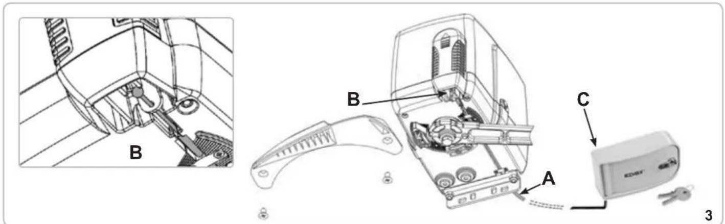
FIXATION ATTACHE MOTEUR A COLONNE (D)
natural_image
Technical line drawing of a door frame with vertical supports and a mounted device (no text or symbols)MONTAGE LEVIERS D'ENTRAINEMENT AVEC DISPOSITIF DE BLOCAGE ANTI-INTRUSION (E)
natural_image
Close-up of a metallic mechanical component with bolts and a curved handle (no visible text or symbols)6
natural_image
Close-up of a mechanical switch tool interacting with a disassembled hard drive (no visible text or symbols)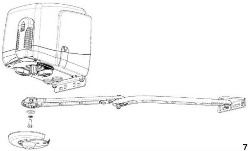
natural_image
Technical line drawing of a mechanical device showing exploded view and assembled assembly (no text or symbols)7
REGLAGE FINS DE COURSE MECANIQUES
natural_image
Black mechanical lever handle with curved arm and mounting bracket (no text or symbols)natural_image
Exterior view of a white electronic device labeled 'EDSK' with two keys beside it (no additional text or symbols visible)DÉCLARATION DE CONFORMITÉ
natural_image
Close-up of a hand inserting a small electronic device into a socket (no visible text or symbols)
natural_image
Technical line drawing of a mechanical assembly with labeled component B (no text or symbols beyond label)
natural_image
Technical line drawing of a door frame with vertical supports and a central horizontal bar (no text or symbols)natural_image
Close-up of a metallic mechanical component with bolts and a curved shaft (no visible text or symbols)5
6
natural_image
Close-up of a mechanical switch tool interacting with a circular mechanical component (no visible text or symbols)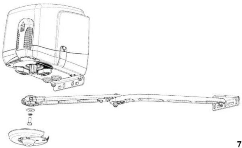
natural_image
Technical line drawing of a mechanical assembly with exploded view and disassembled part (no text or symbols)7
natural_image
Black mechanical lever handle with curved arm and mounting bracket (no text or symbols)natural_image
Exterior view of a white electronic device labeled 'EDSY' with two keys beside it (no additional text or symbols visible)natural_image
Close-up of a hand inserting a small electronic device into a component, no visible text or symbols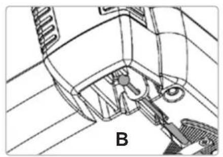
natural_image
Technical line drawing of a mechanical assembly with labeled component B (no text or symbols beyond label)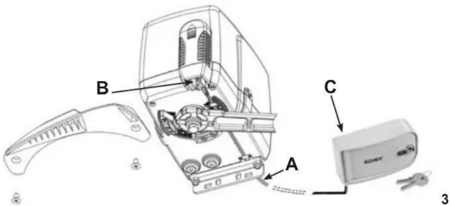
natural_image
Close-up of a metallic mechanical component with bolts and a curved handle (no visible text or symbols)natural_image
Close-up of a mechanical switch tool interacting with a disassembled internal component (no visible text or symbols)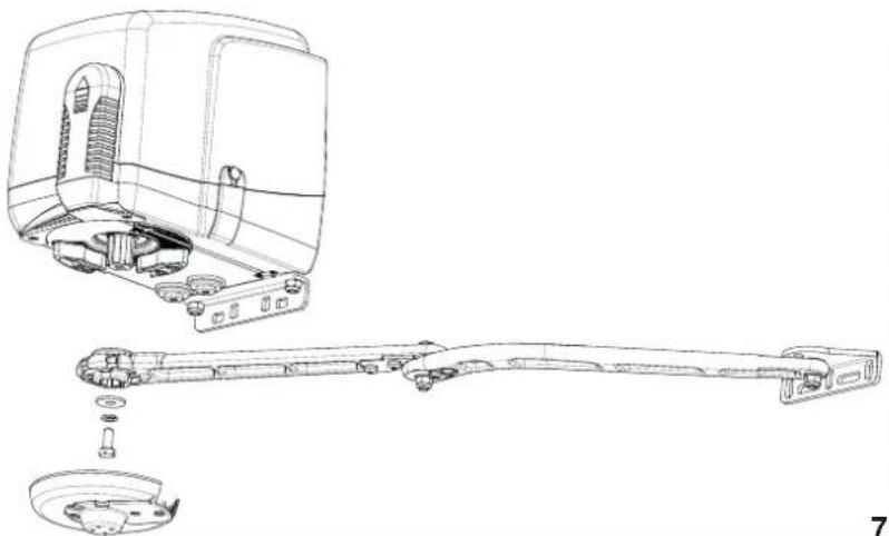
natural_image
Technical line drawing of a mechanical assembly showing exploded view and disassembled components (no text or symbols)7
natural_image
Black mechanical lever handle with curved arm and mounting bracket (no text or symbols visible)natural_image
Exterior view of a white electronic device labeled 'EDMT' with two keys beside it (no additional text or symbols visible)natural_image
Close-up of a hand inserting a small electronic device into a socket (no visible text or symbols)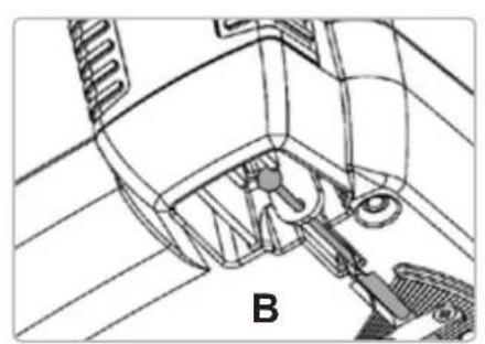
natural_image
Technical line drawing of a mechanical assembly with labeled component B (no text or symbols beyond label)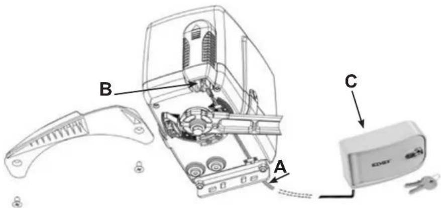
natural_image
Technical line drawing of a door with vertical supports and a mounted device (no text or symbols)natural_image
Close-up of a metallic mechanical component with bolts and a curved handle (no visible text or symbols)6
natural_image
Close-up of a mechanical switch tool interacting with a mechanical component (no visible text or symbols)
natural_image
Technical line drawing of a mechanical device showing exploded view and assembly (no text or symbols)7
natural_image
Black mechanical lever handle with curved arm and circular end (no text or symbols)natural_image
Exterior view of a KORE device with two keys beside it (no text or symbols visible)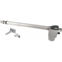


- FISSAGGIO ATTACCO MOTORE A COLONNA (D)
- MONTAGGIO LEVE DI TRAINO CON DISPOSITIVO DI BLOCCAGGIO ANTI-INTRUSIONE (E)
- REGOLAZIONE FINECORSA MECCANICI
- IMPORTANT SAFETY INSTRUCTIONS
- FOR THE INSTALLATION
- FOR THE SAFETY OF THE PEOPLE IT IS IMPORTANT TO FOLLOW ALL THE INSTRUCTIONS.
- FOLLOW ALL INSTALLATION INSTRUCTIONS
- KEEP THESE INSTRUCTIONS WITH CARE
- N.B.: The system must be grounded
- Directive 2002/96/EC (WEEE)
- SYSTEM LAY-OUT
- TECHNICAL FEATURES
- INSTALLATION EKKO ART 200D
- PRE-INSTALLATION CHECK LIST
- Gate features and installation must comply with local regulations and standards.
- EMERGENCY MANUAL RELEASE
- EMERGENCY MANUAL RELEASE THROUGH AN EXTERNAL STRONG BOX
- CAUTION
- FIXING THE OPERATOR TO THE PILLAR (D)
- ASSEMBLING DRIVE ARM WITH THE ANTI-THEFT LOCKING DEVICE (E)
- FIXING THE DRIVE ARM WITH THE ANTI-THEFT LOCKING DEVICE (E)
- ADJUSTMENT OF THE MECHANICAL STOPPERS
- MAINTENANCE
- EC DECLARATION OF CONFORMITY
- ACTUATORS FOR GATES WITH SWING DOORS - SERIES EKKO ART
- INSTRUCTIONS DE SECURITE IMPORTANTES POUR L'INSTALLATION
- POUR LA SECURITE DES PERSONNES IL EST IMPORTANT QUE TOUTES LES INSTRUCTIONS SOIENT SUIVIES
- SUIVRE TOUTES LES INSTRUCTIONS D'INSTALLATION
- Directive 2002/96/CE (WEEE, RAEE)
- FIXATION ATTACHE MOTEUR A COLONNE (D)
- MONTAGE LEVIERS D'ENTRAINEMENT AVEC DISPOSITIF DE BLOCAGE ANTI-INTRUSION (E)
- REGLAGE FINS DE COURSE MECANIQUES
- DÉCLARATION DE CONFORMITÉ
Brand : Vimar
Model : ELVOX EAM6.N
Category : Gate automation