
ELVOX RA98 - Gate automation Vimar - Free user manual and instructions
Find the device manual for free ELVOX RA98 Vimar in PDF.

| Product Type | Control unit for sliding gate and road barrier operators 12 Vdc |
| Brand | Vimar |
| Model | ELVOX RA98 |
| Category | Gate Automation |
| Power Supply | 230 Vac (50/60 Hz) with integrated transformer |
| Motor Rated Power | 50 W |
| Motor Voltage | 12 Vdc |
| Built-in Radio Receiver Capacity | Up to 200 remote controls (fixed or rolling code) |
| Display | Yes, for programming and diagnostics |
| Number of Programmable Parameters | 31 (P01 to P31) |
| Adjustable Opening/Closing Speed | 50-100% of cycle speed |
| Adjustable Slowdown Speed | 20-75% (opening and closing) |
| Slowdown Space | 0-150 cm (adjustable) |
| Obstacle Detection | Yes, by encoder or motor current |
| Safety Inputs | STOP (NC), FOTO (NC), STPA (configurable NC or resistive) |
| Control Inputs | AP/CH (sequential), APED (pedestrians) |
| Auxiliary Outputs | Flashing light (15 W max), courtesy light (65 mA), signaling light (65 mA), accessory power supply (300 mA) |
| Battery Operation | Possible with optional charger (15% speed reduction) |
| Protection Rating | Not specified (indoor installation recommended) |
| Operating Temperature | Not specified |
| Weight | Not specified |
| Dimensions (W x D x H) | Not specified |
| Maintenance | Disconnect power before cleaning; do not attempt to repair yourself |
| Spare Parts | Fuses (2 A, 20 A, 3.15 A), transformer, battery charger |
| Repairability | Repair only by authorized service center |
Frequently Asked Questions - ELVOX RA98 Vimar
User questions about ELVOX RA98 Vimar
0 question about this device. Answer the ones you know or ask your own.
Ask a new question about this device
Download the instructions for your Gate automation in PDF format for free! Find your manual ELVOX RA98 - Vimar and take your electronic device back in hand. On this page are published all the documents necessary for the use of your device. ELVOX RA98 by Vimar.
USER MANUAL ELVOX RA98 Vimar
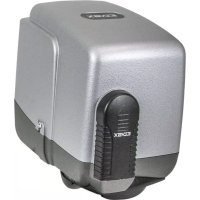
Control panel with display 12 Vdc for sliding gates and road barriers
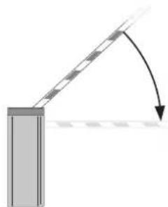
natural_image
Diagram showing a beam passing through a rectangular block with an arrow indicating direction (no text or symbols)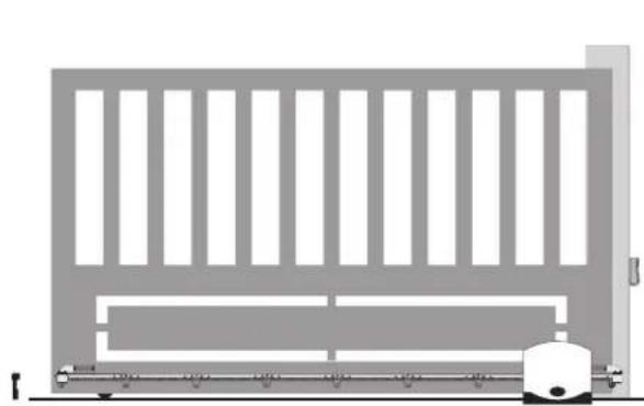
natural_image
Pure architectural elevation diagram of a building facade with vertical slats and horizontal beams, no text or symbols presentCHIUSURA

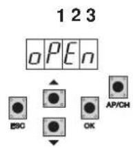
123
RS02
Warnings for the installer
1 - Characteristics....25
2 - Description of the control panel....25
3 - Risk assessment....26
4 - Electricalwiringharnesses....26
5 - Description of LEDs and buttons on the circuit....31
6 - Set the type of actuator....31
7 - Quick programming....32
8 - Complete programming....34
9 - Summary flowchart....40
10 - Installing batteries....43
11 - Troubleshooting....43
12- Programmable parameters....44
13- Installing the card on the 12V sliding ACTUATors with optical encoder....46
WARNINGS FOR THE INSTALLER
- Carefully read all instructions and warnings in this document as they provide important information regarding safety during installation, operation and maintenance.
- After removing the packaging, check the condition of the device. Packaging materials must be kept out of the reach of children as they constitute a hazard. Installation must be carried out in accordance with national safety regulations.
- This device must only be used for the purpose for which it was expressly designed. Any other use is considered improper and therefore hazardous. The manufacturer declines all liability for damage caused by improper, incorrect or unreasonable use.
- Always disconnect the appliance from the power supply at the main switch before performing maintenance or cleaning procedures.
- In the event of faults and/or malfunctions, disconnect the appliance from the power supply immediately at the switch and do not tamper with any of its parts. For repairs, contact only a service centre authorized by the manufacturer. Failure to observe the above may jeopardize the safety of the device.
- All appliances within the system must be used exclusively for the purpose for which they are intended.
- This document must always be kept with all other documentation regarding the installation.

Directive 2002/96/EC (WEEE).
The crossed out bin symbol on the appliance indicates that the product, at the end of its useful working life, must be disposed of separately from normal household waste, and as such must be taken to a waste sorting and recycling centre equipped to deal with electric and electronic equipment, or returned to the dealer when a new appliance of the same type is purchased.
The user is responsible for ensuring the appliance is disposed of through the correct channels when no longer in service. Proper sorted waste collection for subsequent recycling, processing and environmentally conscious disposal of the old appliance helps to prevent any possible negative impact on the environment and human health while promoting the practice of recycling materials used in manufacture. For more detailed information regarding available waste collection systems, contact your local waste disposal service or the shop from which the appliance was purchased.
Risks associated with substances considered hazardous (WEEE).
According to the new WEEE Directive, substances which for some time have been widely used in electrical and electronic equipment are considered hazardous to human health and the environment. Proper sorted waste collection for subsequent recycling, processing and environmentally conscious disposal of the old appliance helps to prevent any possible negative impact on the environment and human health while promoting the practice of recycling materials used in manufacture.
CE
The product complies with European Directive 2004/108/EC and subsequent amendments.
RS02
1- Characteristics
Control panel for governing sliding gear moTors/Sperren and road barriers, 12 V dc with 50 W rated power, equipped with inputs for limit switch, encoder (used for obstacle detection and speed control) integrated receiver and display for programming
The control panel enables:
- customizing the space and speed of deceleration in both opening and closing phases
- equipped with obstacle detection system
- LED for input diagnostics
- removable saved data memory
- integrated receiver with capacity for 200 remote controls (hard coded or rolling code)
- current control for electric motor protection
- log of the last 9 faults or errors.
2- Description of the control panel
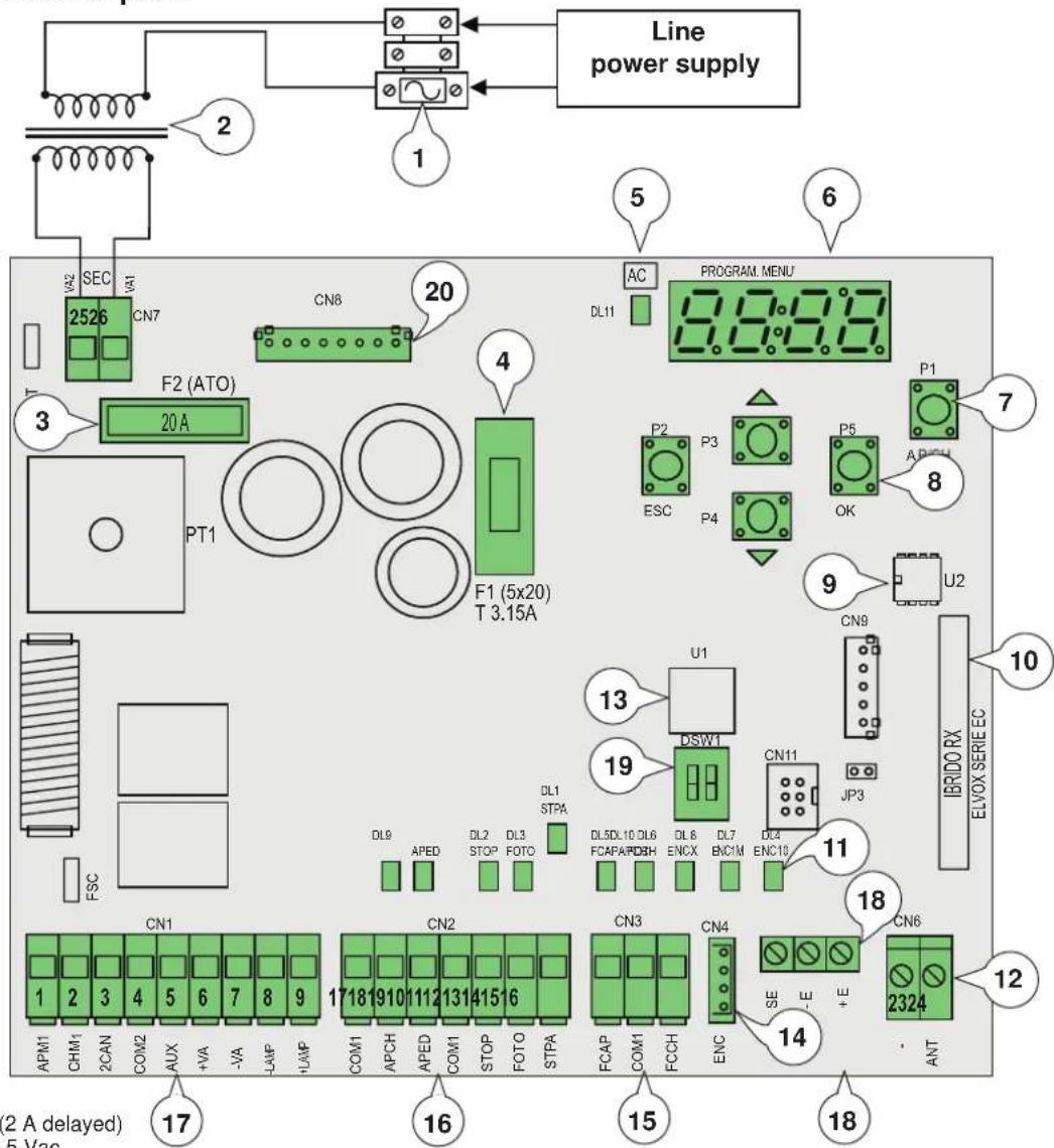
Key:
1- Transformer primary fuse (2 A delayed)
2- Transformer 230 Vac - 13.5 Vac
3- 20 A fuse protecting motor
4- 3.15 A fuse protecting accessories
5- LED signalling mains power supply
6- Display
7- AP/CH control button
8- Buttons for menu scrolling and programming
9- External memory
10- Radio module
11- LED for input diagnostics
12- Terminal for aerial connection
13- Microprocessor
14- Magnetic encoder connector
15- Removable terminal for connecting the limit switches
16- Removable terminal for connecting the control and safety inputs, control panel supplied with jumpered normally closed inputs.
17- Removable terminal for connecting the motor output, flashing light and accessories power supply
18- Optical encoder connector
19- Dip selection sliding / barrier
20- Connector for emergency battery charger card
Fig. 1
RS02
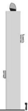
3- Risk assessment
Before starting to install the automatic gate/barrier system it is necessary to evaluate all possible points of danger during the movement of the gate/barrier Fig. 2 highlights some of the danger points of the gate/barrier.
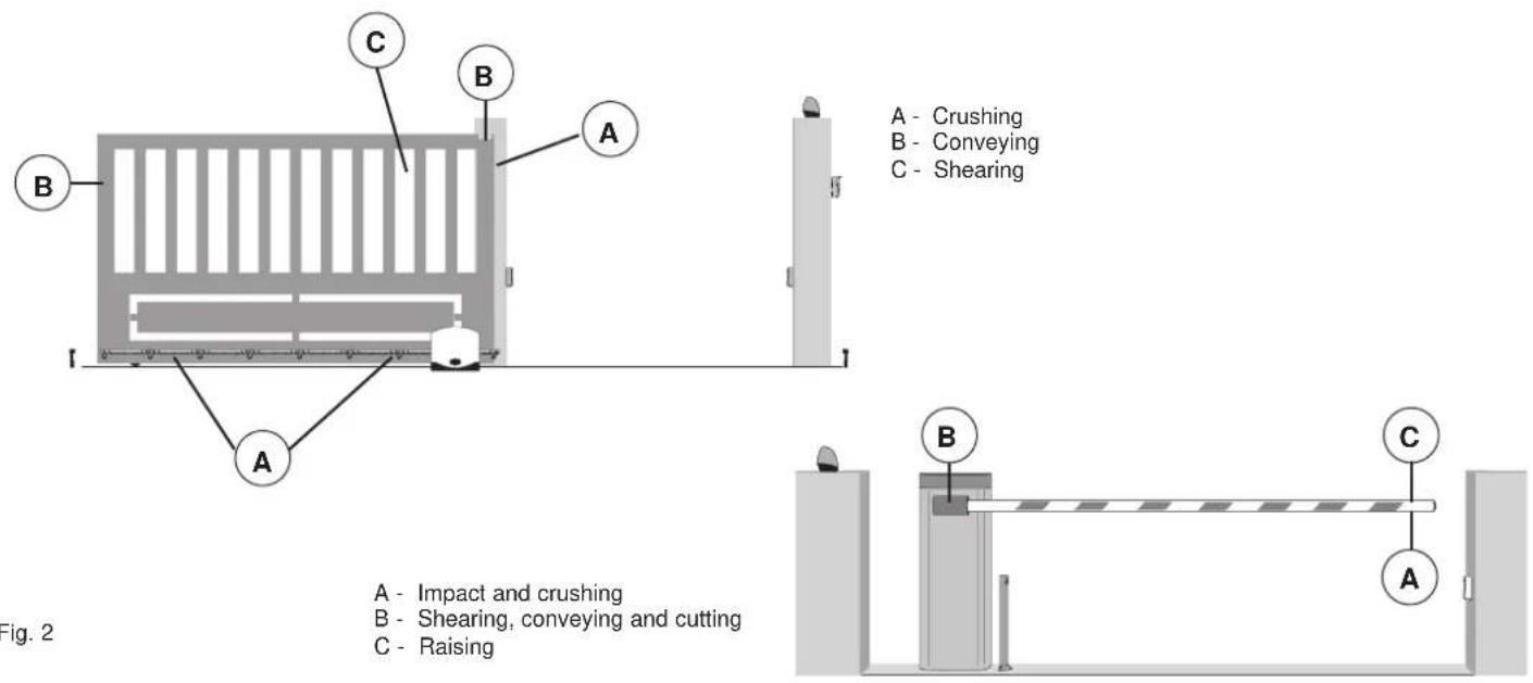
Before starting installation you need to check that the gate/barrier slides properly, that there are secure mechanical stops and check the gate/barrier support system.
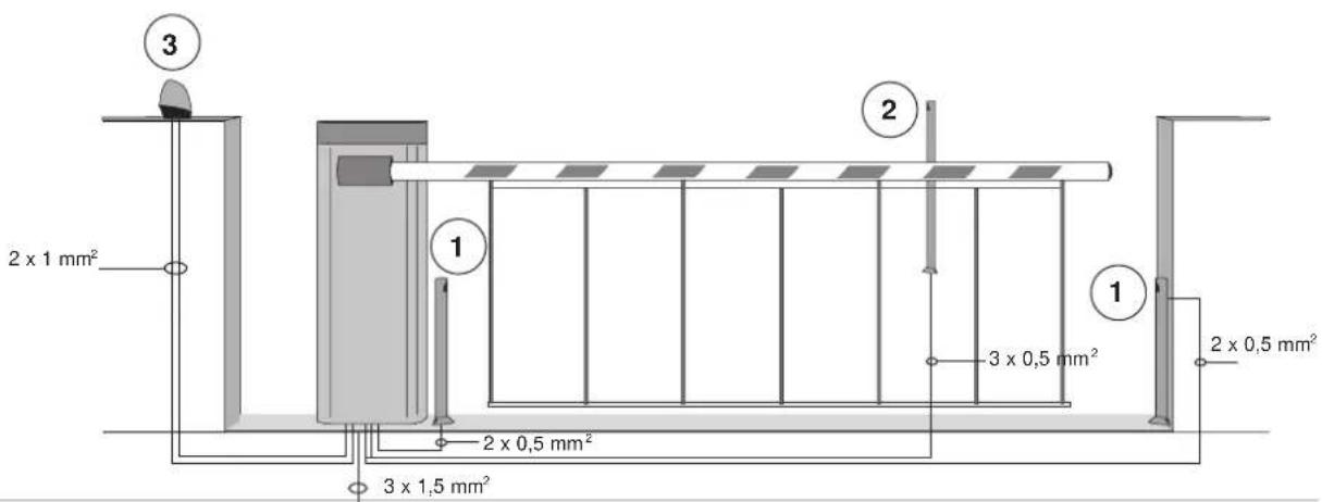
4- Electrical wiring harnesses
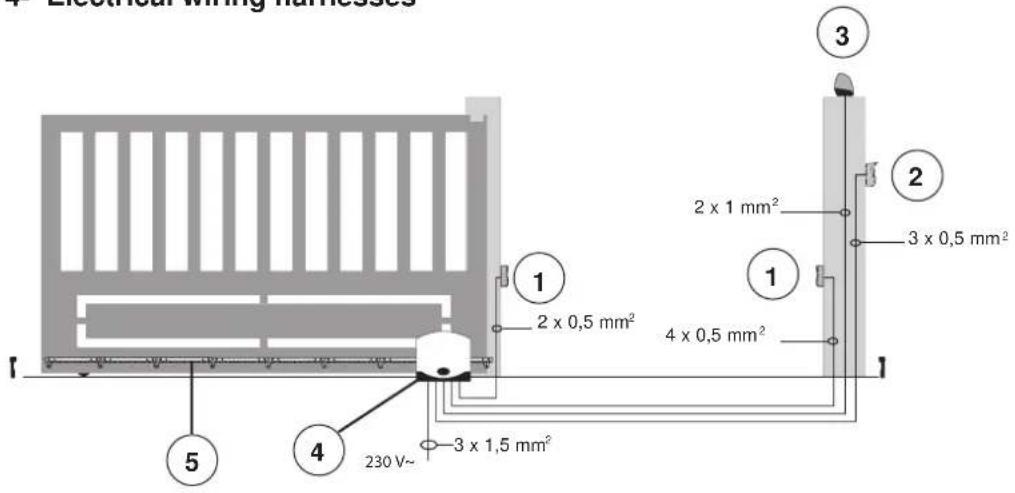
Key:
1 - Photocells
2 - Selector
3 - Flashing light
4 - Gear motor
5 - Rack
Fig. 3
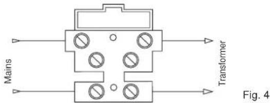
4.1- Power supply line wiring
Inside the transformer compartment there is a terminal with a 2 AT protection fuse, connect the phase in the corresponding pole to the fuse.
Fuse 2 A L 250 V (Mains: 230 V, 240 V)
Fuse 4 A L 250 V (Mains: 110 V, 117 V, 125 V)
4.2- Wiring for flashing light, courtesy light and gate/barrier movement warning light
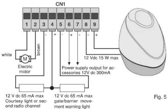
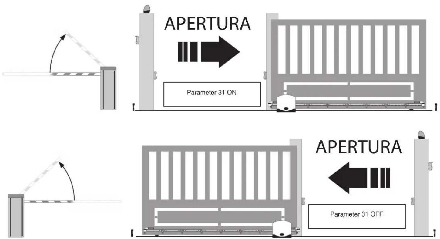
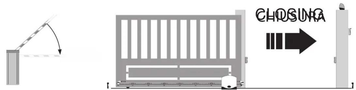
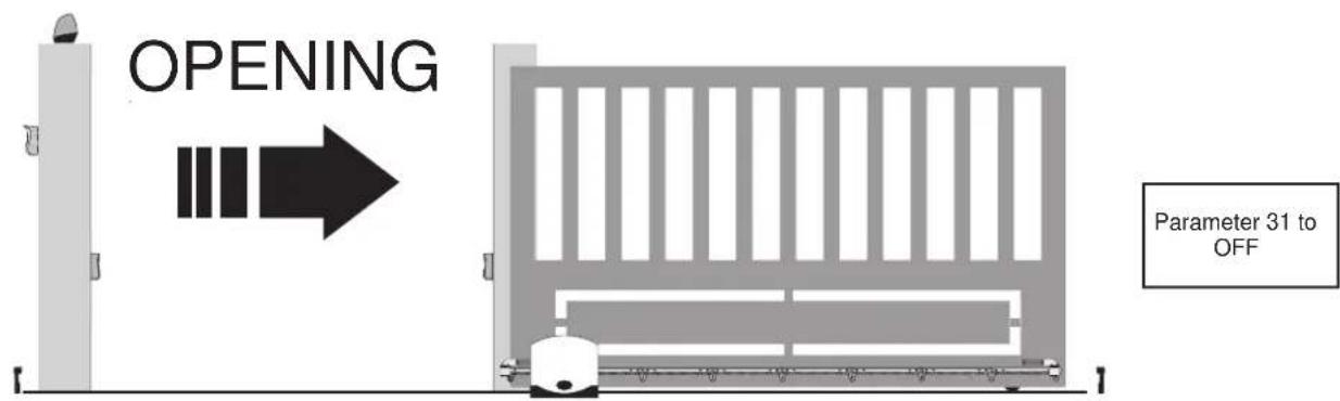
N.B.: Do not change the motor output wiring (terminals 1 and 2) the parameter number 31 selects the direction of opening
| Terminals Description Function | ||
| 1-2 Motor output Output for controlling electric motor 1 | 12 V dc rated power 50 W(terminal number 1 white, terminal number 2 brown) | |
| 3-4 | Courtesy light or second radio channel | Output 12 V dc maximum load 65mA, can be programmed as a timed output (60 seconds) or second radio channel output (3 = GND / 4 = +12 V dc). |
| 4-5 | Warning light output | Output 12 V dc maximum load 65mA, flashes slowly when opening, on with stationary open gate/barrier, flashing fast when closing and off with gate/barrier closed (4= +12 V dc / 5= GND). |
| 6-7 Accessories power supply output Output 12 V dc maximum 300 mA for supplying the photocells and accessories(6 = +12 Vdc, 7= GND) | ||
| 8-9 Output for flashing light Output 12 V dc maximum load 15 W for flashing light (8 = GND, 9 = +12 V dc). | ||
Input description table:
The control unit is supplied with jumpered normally closed inputs (STOP, FOTO and STPA) remove the jumper from the input you are going to use.
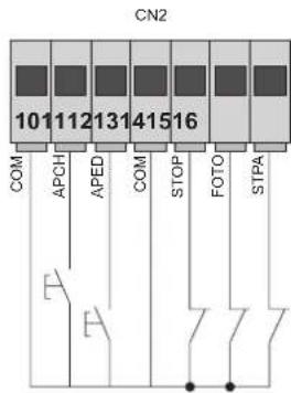
| Terminal number | Description | Input type |
| 10-13-18 | Control inputs common (permanent GND) | - |
| 11 | Sequential control input, for controlling the complete travel of the gate/barrier | Normally open |
| 12 | Sequential control input, for controlling the pedestrian travel of the gate/barrier | Normally open |
| 14 | Input for stopping the gate/barrier | Normally closed |
| 15 | Photocell input, active during gate/barrier closing | Normally closed |
| 16 | Input for edges or internal photocell, active during gate/barrier closing and opening | Configurable: normally closed or balanced at 8.2 K ohm |
| 17 | Opening limit switch input with parameter 31 OFF Closing limit switch input with parameter 31 ON | Normally closed |
| 19 | Closing limit switch input with parameter 31 OFF Opening limit switch input with parameter 31 ON | Normally closed |
RS02
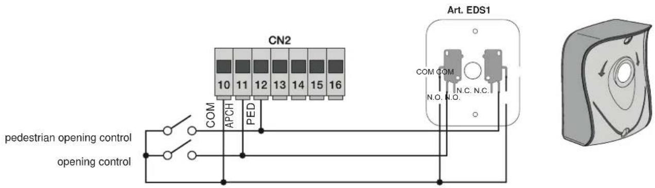
4.3- Connecting control buttons and key switch
Normally open contacts (the red AP/CH or APED LEDS light up when the selector or buttons connected in parallel are operated):
4.4- Connecting photocells
Normally closed contact (when the photocells are not engaged the FOTO LED must be on), if not used then jumper between COM. and PHOTO, you must observe the polarity of the power supply for the photocells:
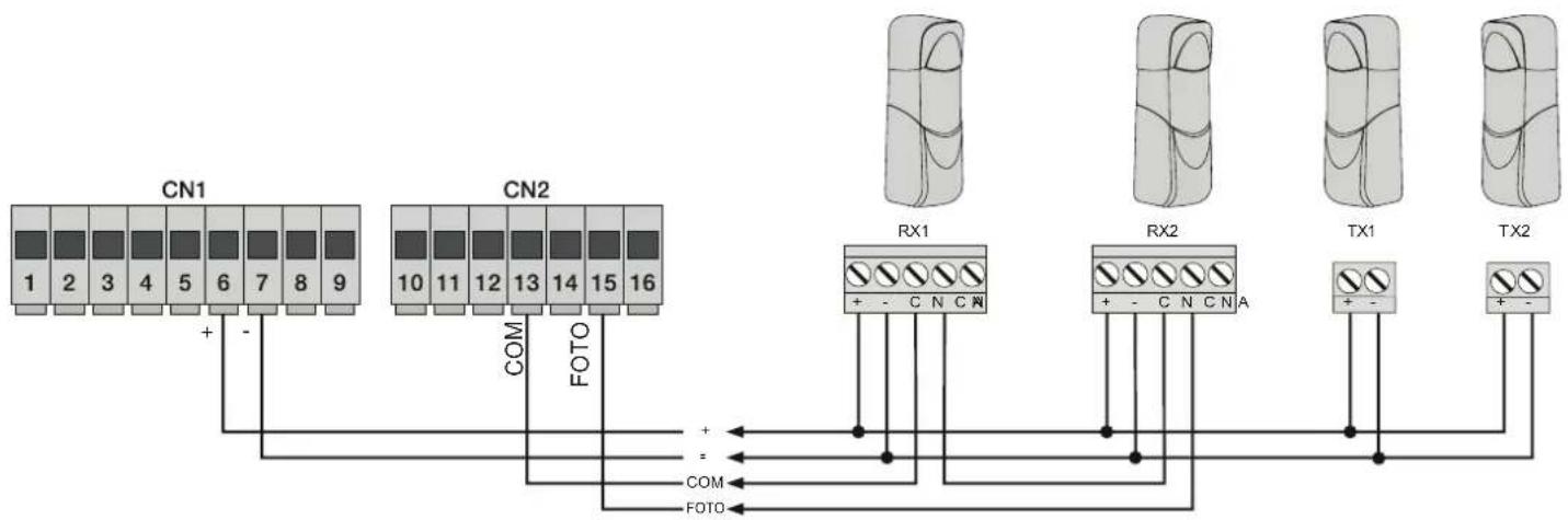
flowchart
graph TD
    A["CN1"] -->|+ -| B["COM"]
    C["CN2"] -->|FOTO| D["RX1"]
    E["CN2"] -->|FOTO| F["RX2"]
    G["CN2"] -->|FOTO| H["TX1"]
    I["CN2"] -->|FOTO| J["TX2"]
Fig. 7
RS02
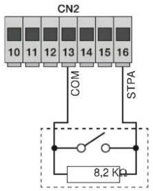
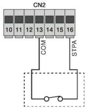
4.5- Sensitive edge connection
With edge or photocell not engaged the STPA LED must be on, see parameter 6. If not used, jumper between COM and STPA. If a switch sensitive edge is connected, parameter 6 must be set to 2 and when connecting a resistive sensitive edge set parameter 6 to 3 (the edge tripping during opening reverses the movement of the gate/barrier by approximately 10 cm whereas during closing it causes total opening).
4.5.1 Resistive sensitive edge connection
Switch edge connection
flowchart
graph TD
    A["CN2"] --> B["10"]
    A --> C["11"]
    A --> D["12"]
    A --> E["13"]
    A --> F["14"]
    A --> G["15"]
    A --> H["16"]
    I["COM"] --> J["STPA"]
    K["Switch"] --> L["Ground"]
Fig. 8
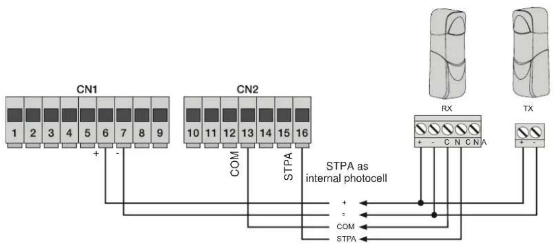
4.6 Connecting internal photocell
If the STPA input is connected to the photocell receiver, set parameter 6 to 1, default setting (if the internal photocell is engaged the gate/barrier will stop, both when opening and when closing, and then it will remain stationary until the photocell is freed, to then start again with opening).
flowchart
graph TD
    A["CN1"] -->|+ -| B["CN2"]
    B -->|COM| C["STPA as internal photocell"]
    C -->|+ -| D["RX"]
    C -->|= | E["TX"]
    C -->|STPA| F["STPA"]
    style A fill:#f9f,stroke:#333
    style B fill:#f9f,stroke:#333
    style C fill:#ccf,stroke:#333
    style D fill:#cfc,stroke:#333
    style E fill:#fcc,stroke:#333
    style F fill:#cff,stroke:#333
Fig. 9
RS02
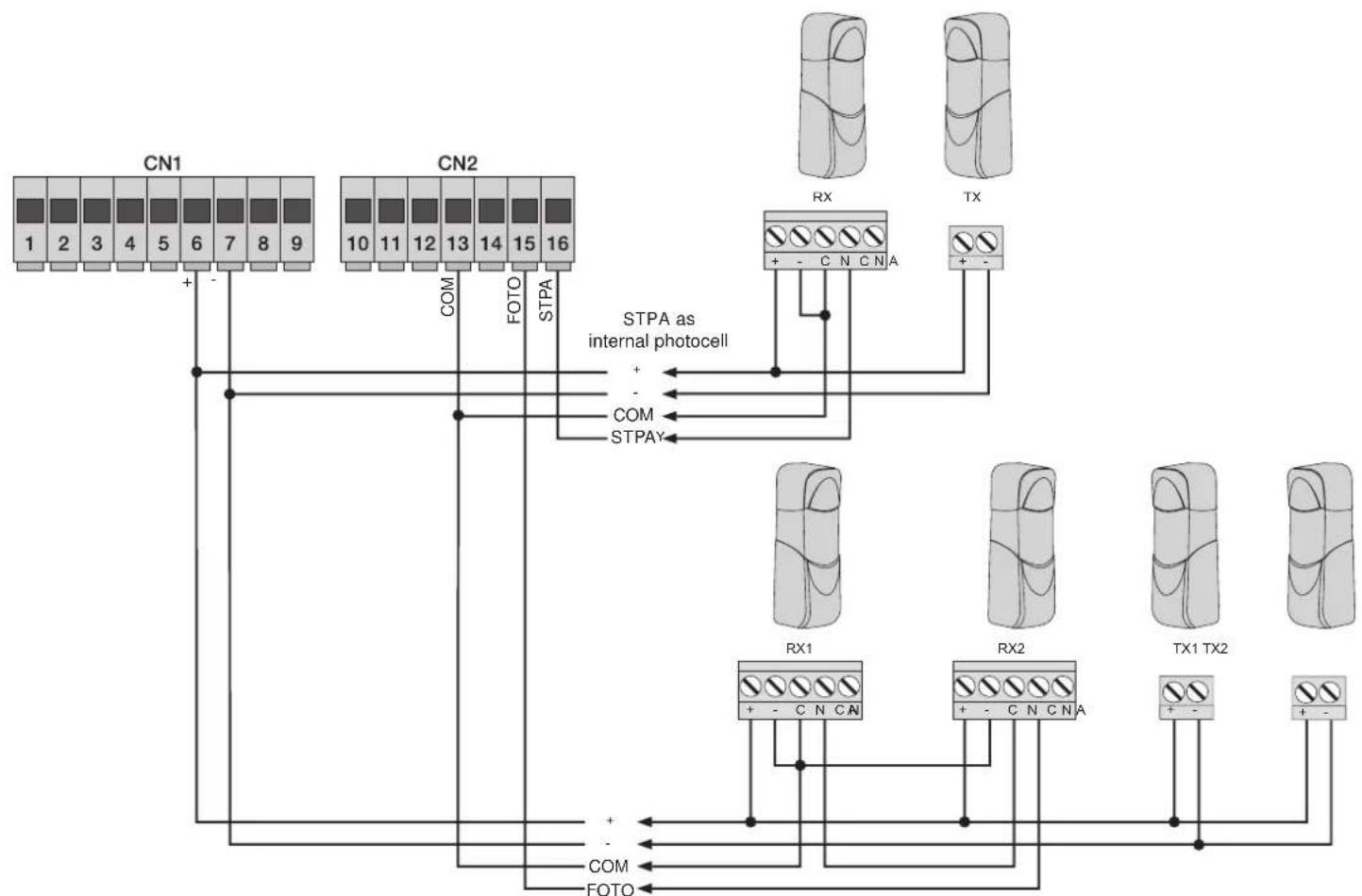
4.6.1 Connecting photocells with photo-test function active
If the photo-test function is activated (the control unit checks the operation of the photocells, see parameter 8), respect the following connection (each time the motor starts the control unit cuts off power to the transmitter of the photocell to check their operation):
flowchart
graph TD
    A["CN1"] -->|+ -| B["STPA as internal photocell"]
    C["CN2"] -->|COM| B
    D["RX"] -->|+ - C N C N A| B
    E["TX"] -->|+ -| B
    F["RX1"] -->|+ - C N C N A| B
    G["RX2"] -->|+ - C N C N A| B
    H["TX1 TX2"] -->|+ -| B
    I["FOTO"] -->|+ -| B
    J["COM"] -->|+ -| B
    K["STPAY"] -->|+ -| B
    B --> L["STPA as internal photocell"]
    style A fill:#f9f,stroke:#333
    style C fill:#f9f,stroke:#333
    style D fill:#ccf,stroke:#333
    style E fill:#ccf,stroke:#333
    style F fill:#ccf,stroke:#333
    style G fill:#ccf,stroke:#333
    style H fill:#ccf,stroke:#333
    style I fill:#ccf,stroke:#333
    style J fill:#ccf,stroke:#333
    style K fill:#ccf,stroke:#333
Fig. 10
4.7- Stop button connection
Stop button connection, normally closed contact, opening the contact causes the gate/barrier to stop and suspends the automatic closing time (when the button is not engaged, the STOP LED should be lit), if not used then jumper between COM and STOP
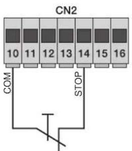
Normally closed button
Fig. 11
N.B. If the system has no photocells, sensitive edges or stop buttons (the PHOTO, STPA and STOP inputs must be jumpered with the common, terminal 13), do not activate the photo-test function.
RS02
4.8- Connecting the aerial
The 17 cm rod is supplied pre-wired, to increase the range connect the aerial art. ZL43, as shown in the figure:
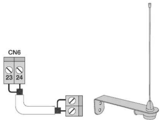
Fig. 12
5 - Description of the LEDs in the circuit
| Abbreviation Description | |
| AC Shows whether there is mains power (lit if there is mains voltage) | |
| STPA | Displays the status of the STPA input (terminal 16), if not engaged the green LED remains lit, if not used then jumper between terminal COM and STPA |
| AP/CH | Displays the status of the AP/CH input (terminal 11), if not engaged the red LED remains off |
| APED | Displays the status of the APED input (terminal 12), if not engaged the red LED remains off |
| STOP | Displays the status of the STOP input (terminal 14), if not engaged the green LED remains lit, if not used then jumper between terminal COM and STOP |
| PHOTO | Displays the status of the FOTO input (terminal 15), if not engaged the green LED remains lit, if not used then jumper between terminal COM and FOTO. |
| FCAP | Displays the status of the opening limit switch with parameter 31 off, the green LED goes out when the gate/barrier is fully open. Displays the status of the closing limit switch with parameter 31 on, the green LED goes out when the gate/barrier is fully closed (OPTIONAL). |
| FCCH | Displays the status of the closing limit switch with parameter 31 off, the green LED goes out when the gate/barrier is fully closed. Displays the status of the opening limit switch with parameter 31 on, the green LED goes out when the gate/barrier is fully open (OPTIONAL). |
| ENC.A | Displays the encoder A input, on steady when the motor is moving at cyclical speed, flashing during slowdown, off with the motor stopped. |
| ENC.B | Displays the encoder B input, on steady when the motor is moving at cyclical speed, flashing during slowdown, off with the motor stopped. |
| PROGRAM MENU DISPLAY | Displays the programming menu |
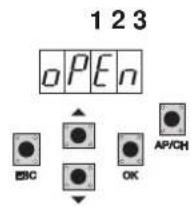
Buttons in the circuit
| Abbreviation Description | |
| AP/CH Controls opening and closing the gate/barrier | |
| ESC Exit or go back to the lower level of the menu | |
| ▲ UP | Increases the displayed value by one unit or scrolling on the same menu level |
| ▼ DOWN | Decreases the displayed value by one unit or scrolling on the same menu level |
| ENTER | Confirms the value or moves to the top level of the menu, when pressed while the gate/barrier is moving it shows the absorption of the electric motor in Amps |
Preliminary check:
After powering up the control panel, the display shows the name of the control panel RS02, the firmware version Fxxx and 3 flashes with the words FLSH and then switches off. Check the diagnostic LEDs of the inputs, the STOP, FOTO, STPA, FCAP and FCCH LEDs must be on (if the limit switches are not engaged). Should one of the safety inputs (FOTO, STOP, STPA) not be used, insert a jumper between COM and the input not used.
6 - Set the type of actuator
DSW1.1 = OFF function as sliding
DSW1.1 = ON operation as a road barrier
RS02
7- Quick programming
Procedure for facilitated gate/barrier travel programming:
N.B.: Before you start programming, check parameter 31 (opening direction)
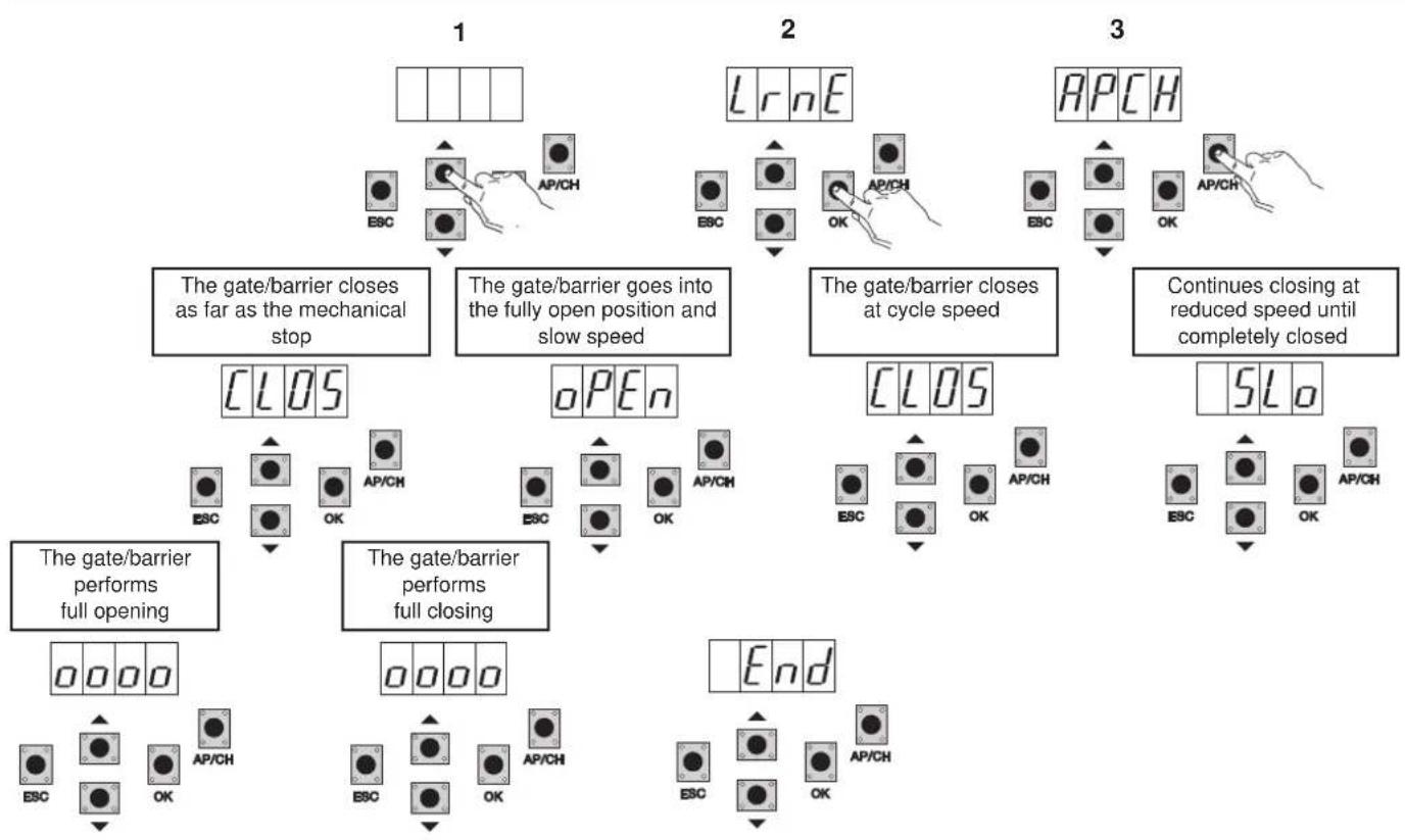
7.1- Procedure for facilitated gate/barrier travel programming:
RS02
flowchart
graph TD
A["1: The gate/barrier closes as far as the mechanical stop"] --> B["2: The gate/barrier goes into the fully open position and slow speed"]
B --> C["3: The gate/barrier closes at cycle speed"]
C --> D["4: Continues closing at reduced speed until completely closed"]
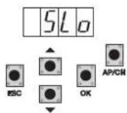
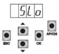
D --> E["5: SLo"]
E --> F["End"]
subgraph State 1
G["ESC"] --> H["AP/CH"]
end
subgraph State 2
I["Lr nE"] --> J["ESC"]
J --> K["OK"]
K --> L["AP/CH"]
L --> M["AP/CH"]
M --> N["OK"]
end
subgraph State 3
O["ESC"] --> P["AP/CH"]
Q["OK"] --> R["AP/CH"]
R --> S["AP/CH"]
S --> T["Open"]
end
subgraph State 4
U["CLOS"] --> V["ESC"]
W["OPEN"] --> X["OK"]
Y["CLOS"] --> Z["ESC"]
AA["SLo"] --> AB["ESC"]
AC["End"] --> AD["ESC"]
AE["Start"] --> AF["OK"]
end
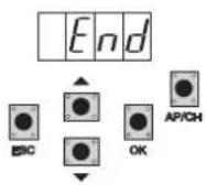
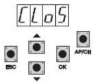
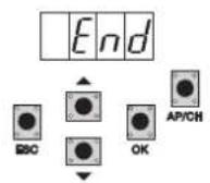
Starting with the gate/barrier not fully closed, after entering programming mode by pressing the UP, OK, and AP/CH button once, the gate/barrier starts closing to find the mechanical stop for closing. It automatically starts opening at low speed until it reaches the mechanical stop for opening. After 2 seconds the gate/barrier starts closing at cycle speed and slows down approximately 50 cm from complete closing and continues until completely closed. The control panel saves the gate/barrier travel and automatically performs a complete opening and closing cycle to save the current thresholds with default deceleration speed and distances. The word END on the display indicates the end of calibration.
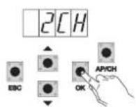
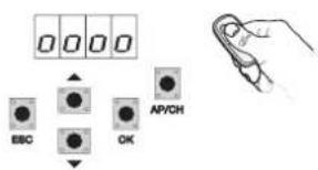
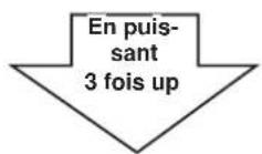
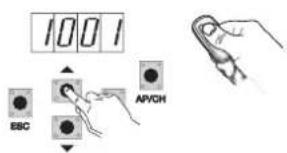
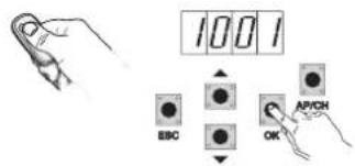
7.2 Procedure for saving a remote control associated with button APCH:
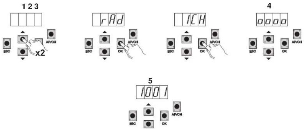
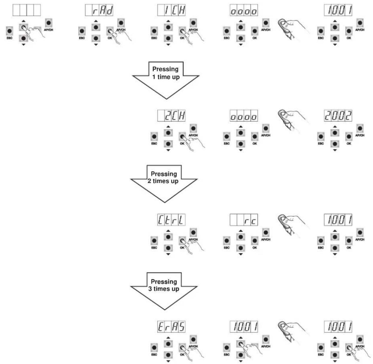
Press the UP button 2 times, the display will show RAD
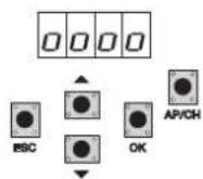
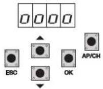
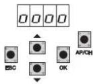
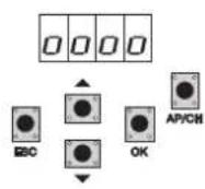
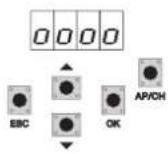
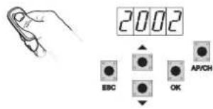
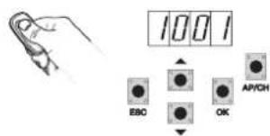
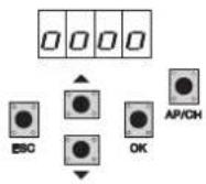
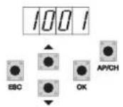
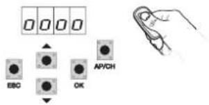
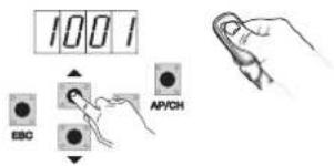
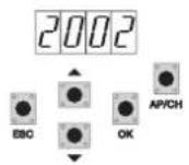
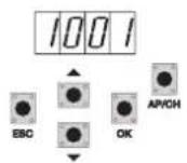
Press the OK button, the display will show 1CH (indicating that the remote control button will be saved as AP/CH of the control panel) Press the OK button, 4 dots will appear on the display, indicating that the control panel is waiting for a remote control button to be tapped (timeout 10 seconds) After pressing the remote control button the display will show a 4-digit number: the first digit indicates association (1 controls the AP/CH input 2 controls the pedestrian entrance or the second channel output) the other 3 indicate the memory cell occupied by the remote control (the first remote control occupies cell 001, the second one cell 002), the maximum capacity is 200 remote controls To save other remote controls repeat the procedure.
N.B.: The first saved remote control configures the control panel to accept only remote controls with a rolling code or only remote controls with a fixed 12-bit code
RS02
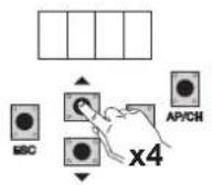
7.3 Example of the procedure for changing the automatic closing time:
12345
6
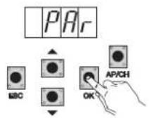
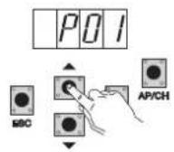
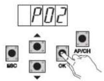
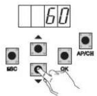
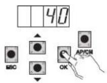
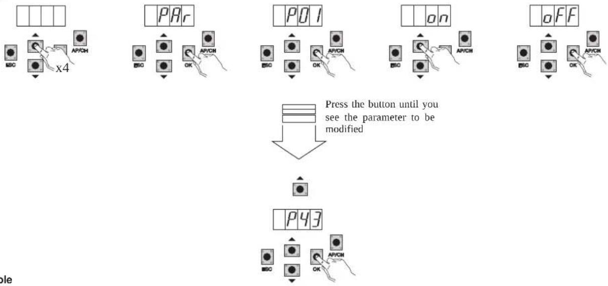
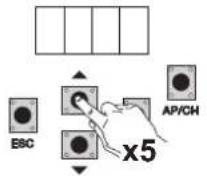
Press the UP button 4 times, the display will show PAR (parameters)
Press OK, the display will show P01
Press the UP button once, the display will show P02 (automatic closing time)
Press the OK button, the display will show the automatic closing time
With the DOWN or UP button you can vary the automatic closing time
Press the OK button to confirm and save the modified value
8- Full description of the programming menu.
The programming menu is divided into 3 levels: first the main level, second the parameters level and third the values level
Main menu:
| Display Message Description |
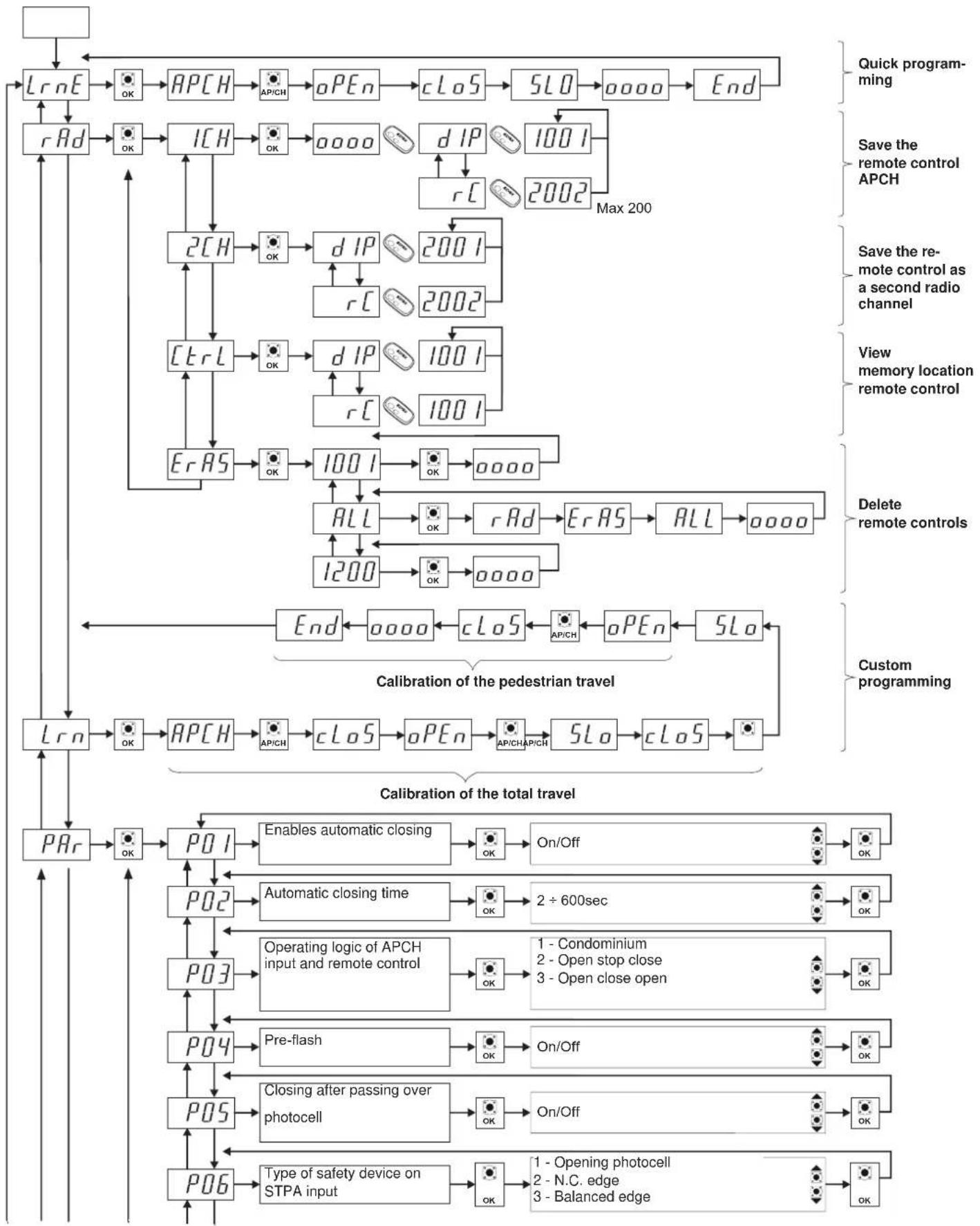
| LRNE Learning travel with quick programming (see section 6) |
| RAD Remote control management |
| LRN Learning travel with custom programming |
| PAR Used to modify all the parameters of the control panel |
| DEF Used to go back to the default values |
| CNT Used to view the manoeuvres carried out |
| ERR Used to view a list of the last 9 errors or malfunctions |
| PASS Control panel protection level setting |
After selecting the desired item from the main menu by pressing the UP or DOWN button, confirm by pressing OK.
8.1 LRNE: quick procedure for programming gate/barrier travel
natural_image
Diagram showing a beam passing through a vertical prism with an arrow indicating direction (no text or symbols)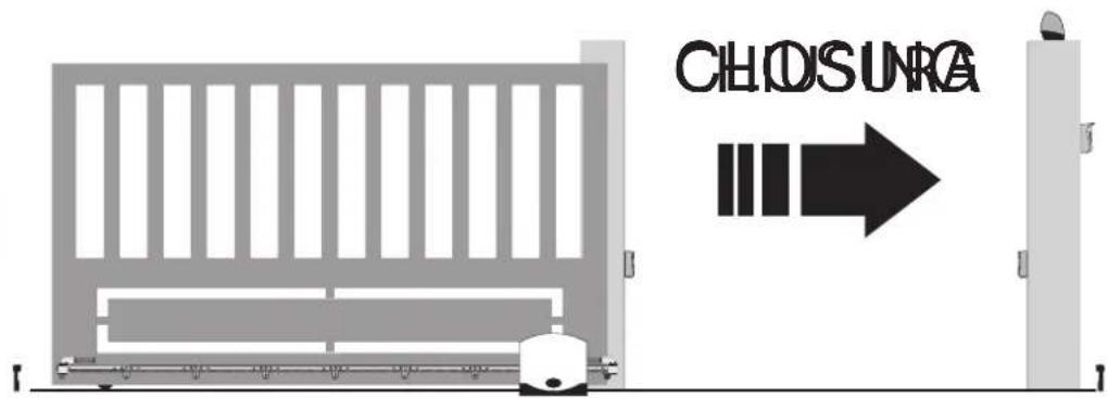
RS02
Starting with the gate/barrier not fully closed, after entering programming mode by pressing the UP, OK, and AP/CH button once, the gate/barrier starts closing to find the mechanical stop for closing. It automatically starts opening at low speed until it reaches the mechanical stop for opening. After 2 seconds the gate/barrier starts closing at cycle speed and slows down approximately 50 cm from the mechanical catch and continues until completely closed. The control panel saves the gate/barrier travel and automatically performs a complete opening and closing cycle to save the current thresholds with default deceleration speed and distances. The word END on the display indicates the end of calibration.
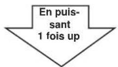
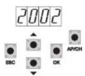
8.2 RAD: remote control management menu is divided into 4 parameters:
flowchart
graph TD
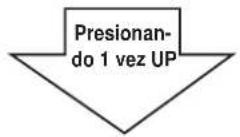
A["Pressing 1 time up"] --> B["Pressing 2 times up"]
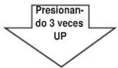
B --> C["Pressing 3 times up"]
subgraph Pressing 1 time up
D["ECB"] --> E["rAD"]
E --> F["EBO"]
F --> G["AP/CH OK"]
G --> H["ICH"]
H --> I["EOC"]
I --> J["AP/CH OK"]
J --> K["0000"]
K --> L["EBO"]
L --> M["AP/CH OK"]
M --> N["1001"]
N --> O["EOC"]
O --> P["AP/CH OK"]
end
subgraph Pressing 2 times up
Q["ECB"] --> R["2CH"]
R --> S["EBO"]
S --> T["AP/CH OK"]
T --> U["0000"]
U --> V["EBO"]
V --> W["AP/CH OK"]
W --> X["2002"]
X --> Y["EOC"]
Y --> Z["AP/CH OK"]
end
subgraph Pressing 3 times up
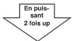
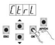
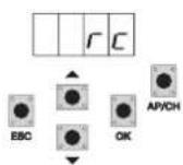
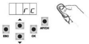
AA["ECB"] --> AB["ctrl"]
AB --> AC["EBO"]
AC --> AD["AP/CH OK"]
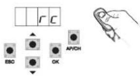
AD --> AE["rC"]
AE --> AF["EBO"]
AF --> AG["AP/CH OK"]
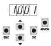
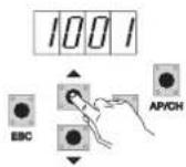
AG --> AH["1001"]
AH --> AI["EOC"]
AI --> AJ["AP/CH OK"]
end
subgraph Pressing 3 times up
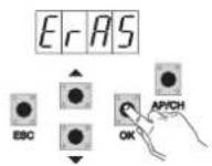
AK["ErAS"] --> AL["EBO"]
AL --> AM["AP/CH OK"]
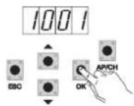
AM --> AN["1001"]
AN --> AO["EBO"]
AO --> AP["AP/CH OK"]
AP --> AQ["1001"]
end
RS02
Description of RAD menu parameters:
Display
Message
Description Display message after activating the remote control
1 CH Used to save the remote control button corresponding to the input AP/CH 1***
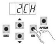
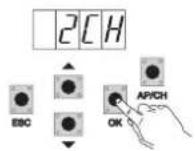
2 CH Used to save the remote control button corresponding to the input PED or output 2CAN
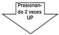
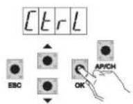
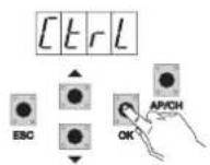
CTRL Pressing the button on the remote control lets you compare and see where the memory cell has been saved.
2***
1*** or 2***
ERAS Used to delete a remote control in the memory list or all the remote controls in the memory.
After selecting the remote control from the list press OK and the display will show 0000 to confirm deletion. To delete all the remote controls select ALL between 200 and 001 and press OK, the display will show 0000
N.B. The first saved remote control configures the control panel to accept only remote controls with a rolling code or only remote controls with a fixed 12-bit code
If you need to delete all the remote controls, enter the RAD menu, select ALL (between number 001 and 200), press and hold the OK button for 5 at least seconds, and the display will show the 4 dots confirming the operation.
It is advisable to fill in the final table indicating the number of the memory cell (it is displayed while saving the remote control) in the user name, this enables deleting a remote control should it get lost.
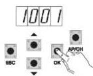
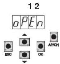
8.3 LRN: Learning travel with custom programming lets you define the points for starting deceleration when both opening and closing:
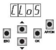
CHOSINRA
x3
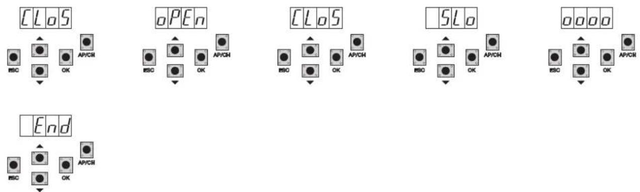
- starting with the gate/barrier not completely closed, press the UP button until the display reads LRN, confirm with the OK button to enter the programming mode, the display will show APCH
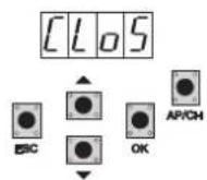
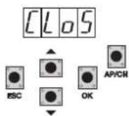
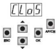
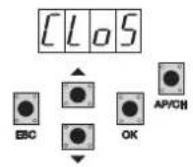
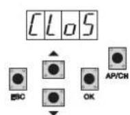
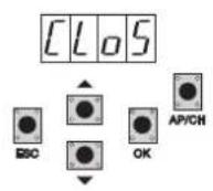
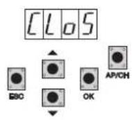
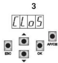
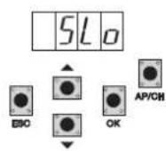
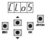
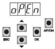
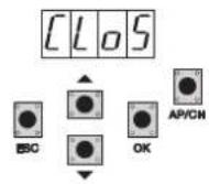
- press and release the AP/CH button, the gate/barrier will close and the display will show CLOS
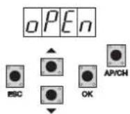
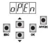
- on completely closing the gate/barrier will start opening and the display will show OPEN
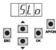
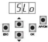
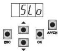
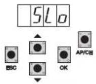
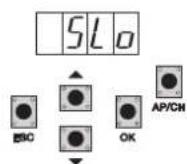
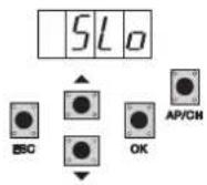
- press and release the AP/CH button to determine the starting point of deceleration on opening and the display will show the message SLO
- the gate/barrier continues to slow down until it is fully opened and then automatically starts closing again, the display will show CLOS
- press and release the AP/CH button to determine the starting point of deceleration on closing and the display will show the message SLO
- the gate/barrier continues to slow down until completely closed
- the gate/barrier opens and the display shows OPEN (calibration of the pedestrian opening distance)
- press and release the AP/CH button to determine the pedestrian opening distance
- the gate/barrier closes completely and the display shows CLOS
RS02
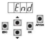
- the gate/barrier opens and closes completely and the display shows 4 dots (reading the current thresholds)
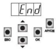
- when completely closed, the display shows END, indicating that the travel has been saved correctly.
8.4 PAR: Used to modify all the parameters of the control unit, press the UP button until PAR appears on the display, confirm with the OK button to display the list of parameters, the display will show P 01 (parameter number 1), the UP or DOWN button lets you scroll through the list of parameters (see parameter table).
flowchart
graph TD
    A["Start"] --> B["x4"]
    B --> C["Press the button until you see the parameter to be modified"]
    C --> D["OK"]
    D --> E["Press the button until you see the parameter to be modified"]
    E --> F["OK"]
    F --> G["Press the button until you see the parameter to be modified"]
Parameter table
| Number of parameter | Description Settable values | Default value | Modified value | |
| P01 Enables automatic closing ON/OFF ON | ||||
| P02 Sets the automatic closing time 2-600 seconds 60 seconds | ||||
| P03 AP/CH input operation 1= when opening, AP/CH input not active (condo)2=AP/CH as sequential (open, stop, close, stop..)3=AP/CH as sequential (open, open, close..) | 1 | |||
| P04 Pre-flash ON/OFF ON | ||||
| P05 Closing after photocell disengage-ment | ON/OFF OFF | |||
| P06 Type of safety device connected to the STPA input | 1= photocell as protection on opening(if engaged it stops the gate/barrier, until it is disengaged, and then it continues in the same direction)2= microswitch sensitive edge3= resistive sensitive edge (balanced with resistance (8.2Kohm)4= photocell as internal protection (if engaged it stops the gate/barrier, until it is disengaged, then it continues opening) | 1 | ||
| P07 AUX output operating mode 1= disabled | 2= flashes while the gate/barrier is moving3= flashes while the gate/barrier is moving and stays on steady when the gate/barrier is stationary | 2 | ||
| P08 Enables photocell control | 0= Control disabled, 1= Control on FOTO input2= Control on STPA input, 3= Control on STPA and FOTO inputs 0 | |||
| P09 Slowdown distance when closing 0-150cm 73cm | ||||
| P10 Slowdown distance when opening 0-150cm 49 cm | ||||
| P11 | Opening speed 50-100% | 100% | ||
| P12 Closing speed 50-100% | 100% | |||
| P13 Opening deceleration speed 20-75% - Minimum speed 20% | 50% | |||
| P14 Closing deceleration speed 20-75% - Minimum speed 20% | 50% | |||
| P15 Motor force Min. 1-10 max | 5 | |||
| P16 Intensity of stopping with opening limit switch tripping | 0-100= instantaneous stop10= soft stop | 5 | ||
| P17 Intensity of stopping with closing limit switch tripping | 0-100= instantaneous stop10= soft stop | 5 | ||
| P18 Separate buttons | 0= AP/CH controls complete opening and closing of the gate/barrier,PED controls partial opening and closing of the gate/barrier1= input AP/CH, controls opening only and inputPED, controls closing only2= input AP/CH and the button of the remote control saved as CH1controls opening only and the PED input and the button of the remotecontrol saved as CH2 controls closing only | 0 | ||
RS02
| Parameter number | Description | Settable values | Default value | Modified value |
| P19 Operating logic of the FOTO input | 1: the FOTO input tripping reverses the movement of the gate/barrier during closing2: the FOTO input tripping stops the movement of the gate/barrier during opening and closing, when disengaged it goes back to opening again | 1 | ||
| P20 Selects the operation of the second button on the remote control | 2CAN= activates the 2CH outputPEDO= controls pedestrian opening | 0 | ||
| P21 Channel 2 output activation time 1-60 seconds 1 second | ||||
| P22 Pedestrian opening distance 50-250 cm 148 cm | ||||
| P23 Type of encoder 1- Magnetic encoder, 2- Optical encoder 1 | ||||
| P24 Acceleration on starting 1-5 (1=maximum acceleration) | 5= minimum acceleration) 3 | |||
| P25 Deceleration on slowing down 1-8 (8= maximum deceleration 1= minimum deceleration) 7 | ||||
| P26 Operation with limit switch OFF = no limit switch | OFF | |||
| OP = opening limit switch fittedCL= closing limit switch fittedOPCL= opening and closing limit switch fitted | ||||
| P27 Flashing light active also when running only on battery | ON/OFF | OFF | ||
| P28 Operation with battery | 0: functionality does not change1: after an apch command the gate/barrier opens and remains open2: the gate/barrier opens and remains open | 0 | ||
| P29 | Manned, AP/CH controls opening by keeping the button pressed, PED controls closing by keeping the button pressed | 0: function disabled1: function active if the safety devices are open (FOTO and STPA)2: function active with apch and ped inputs, maintains automatic operation if controlled remotely | 0 | |
| P30 - | - | - | ||
| P31 Selecting the direction of opening the gate/barrier | OFF: opens to the leftON: opens to the right | OFF | ||
N.B.: After calibrating the travel, if parameters 11-12-13-14 and 31 are changed after confirming with the ENTER key the display reads APCH, you must give the command by pressing the APCH button, the gate/barrier will perform a complete opening and closing cycle (with this operation, the control unit saves the new current thresholds with the modified speeds)
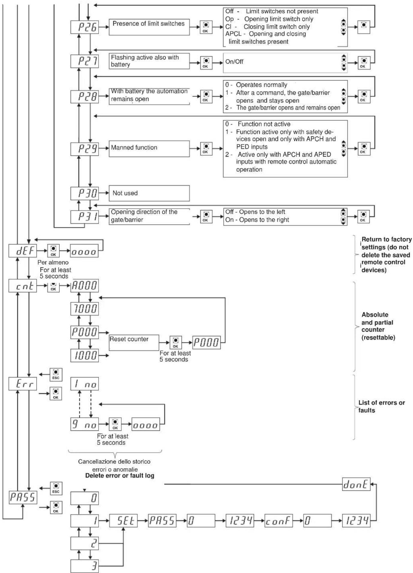
8.5 DEF: used to set the control panel on the default parameters, except for parameters: 9-10-11-12-13-14-15-22-23-24-26-31 press and release the OK button, the display shows 4 dots to confirm the operation.
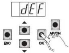
N.B. To set all the parameters to default: power up the control panel by holding down the ESC key for at least 10 seconds.
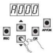
8.6 CNT: used to view the number of openings followed by the gearmotor, the first counter A displays the number of absolute operations, the second counter P displays the operations performed after a reset controlled by the installer. This is shown in the following example:
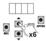
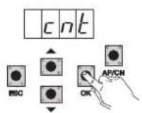
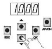
Pressing the UP button 6 times displays CNT (counter)
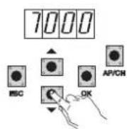
Press the OK button, the display shows the letter A (absolute counter cannot be reset) the number that follows should be multiplied by 10000. Press the DOWN button, the display shows the number to be added to get the total openings performed by the motor: absolute number = (000*10000)+(7000)= 7000
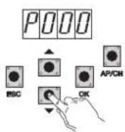
Press the DOWN button, the display shows the letter P (partial counter can be reset) the number that follows should be multiplied by 10000. Press the DOWN button, the display shows the number to be added to get the openings after resetting the partial counter: partial number = (000*10000)+(1000)= 1000, this means that it was reset on 6000 openings. To reset the partial counter, press and hold down the OK button for at least 5 seconds.
RS02
8.7 ERR: Shows the last 9 faults or errors: when the gate/barrier is not moving, you can view the last fault during operation
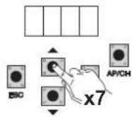
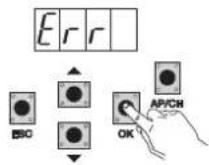
Pressing the UP button 7 times displays Err (list of faults or errors)
Press the OK button, the display shows the letter 1.F Xx, the first digit indicates the progressive error log number, ranging from 1 to 9, the highest value indicates the most recent error, xx indicates the type of error, see the errors table:
To clear the error list: enter the ERR menu and hold down the OK button for at least 5 seconds.
| Display message Description | |
| no No alarm saved in the location | |
| F01 Detected a problem on the output powering the motor | |
| F02 Detected an obstacle during the opening movement | |
| F03 Detected an obstacle during the closing movement | |
| F04 FOTO input contact open | |
| F05 A condition has occurred causing the motor to stop | |
| F06 STPA input contact open | |
| F07 External memory damaged | |
| F08 The encoder input is not read correctly or there is no connection between the control panel and the encoder | |
| F09 Occurs when the time out is exceeded during programming | |
| F10 Fuse damaged or blown | |
| F11 Detected too high current absorption on the motor power output | |
| F13 Incorrect electric motor wiring, reverse the wires of the electric motor |
7.8 - PASS: you can enable a password with 3 levels, with level 1 password is required to enter the menu PAR, DEF, and LRNE LRN, with level 2 password is required to enter the menu RAD, with level 3 password is required to enter all the menu items (LRNE, LRN, DEF, RAD, CNT, PAR ERR).
NB: In case you lost your password you need to call the service center
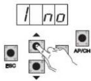
Example of entering the password 4-3-2-1 on the second level:
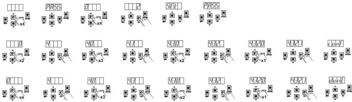
If you enter the password to level 1-2 or 3 when you select the menu item will be prompted for the password-protected, enter the password and confirm with OK, if you exit the menu will be prompted for the password.
If the password is incorrect in the display shows NO.
9-Summary flowchart:
flowchart
graph TD
A[" "] --> B["Lr nE"]
B --> C["OK"]
C --> D["APCH"]
D --> E["AP/CH"]
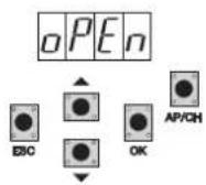
E --> F["oPEn"]
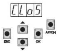
F --> G["cLoS"]
G --> H["5LO"]
H --> I["0000"]
I --> J["End"]
J --> K["Quick programming"]
K --> L["rAd"]
L --> M["OK"]
M --> N["ICH"]
N --> O["OK"]
O --> P["0000"]
P --> Q["d IP"]
Q --> R["1001"]
R --> S["rC"]
S --> T["2002"]
T --> U["Max 200"]
U --> V["2CH"]
V --> W["OK"]
W --> X["d IP"]
X --> Y["2001"]
Y --> Z["rC"]
Z --> AA["2002"]
AA --> AB["Ctrl"]
AB --> AC["OK"]
AC --> AD["d IP"]
AD --> AE["1001"]
AE --> AF["rC"]
AF --> AG["1001"]
AG --> AH["ErAS"]
AH --> AI["OK"]
AI --> AJ["1001"]
AJ --> AK["ALL"]
AK --> AL["OK"]
AL --> AM["rAd"]
AM --> AN["All"]
AN --> AO["0000"]
AO --> AP["1200"]
AP --> AQ["OK"]
AQ --> AR["0000"]
AR --> AS["Custom programming"]
AS --> AT["Lr n"]
AT --> AU["OK"]
AU --> AV["APCH"]
AV --> AW["AP/CH"]
AW --> AX["cLoS"]
AX --> AY["oPEn"]
AY --> AZ["5Lo"]
AZ --> BA["cLoS"]
BA --> BB["End"]
BB --> BC["Calibration of the pedestrian travel"]
BC --> BD["Calibration of the total travel"]
BD --> BE["PQ1"]
BE --> BF["Enable automatic closing"]
BF --> BG["OK"]
BG --> BH["On/Off"]
BH --> BI["OK"]
BI --> BJ["PQ2"]
BJ --> BK["Automatic closing time"]
BK --> BL["OK"]
BL --> BM["2 + 600sec"]
BM --> BN["OK"]
BN --> BO["PQ3"]
BO --> BP["Operating logic of APCH input and remote control"]
BP --> BQ["OK"]
BQ --> BR["1 - Condominium\n2 - Open stop close\n3 - Open close open"]
BR --> BS["OK"]
BS --> BT["PQ4"]
BT --> BU["Pre-flash"]
BU --> BV["OK"]
BV --> BW["On/Off"]
BW --> BX["OK"]
BX --> BY["PQ5"]
BY --> BZ["Closing after passing over photocell"]
BZ --> CA["OK"]
CA --> CB["On/Off"]
CB --> CC["OK"]
CC --> CD["PQ6"]
CD --> CE["Type of safety device on STPA input"]
CE --> CF["OK"]
CF --> CG["1 - Opening photocell\n2 - N.C. edge\n3 - Balanced edge"]
CG --> CH["OK"]
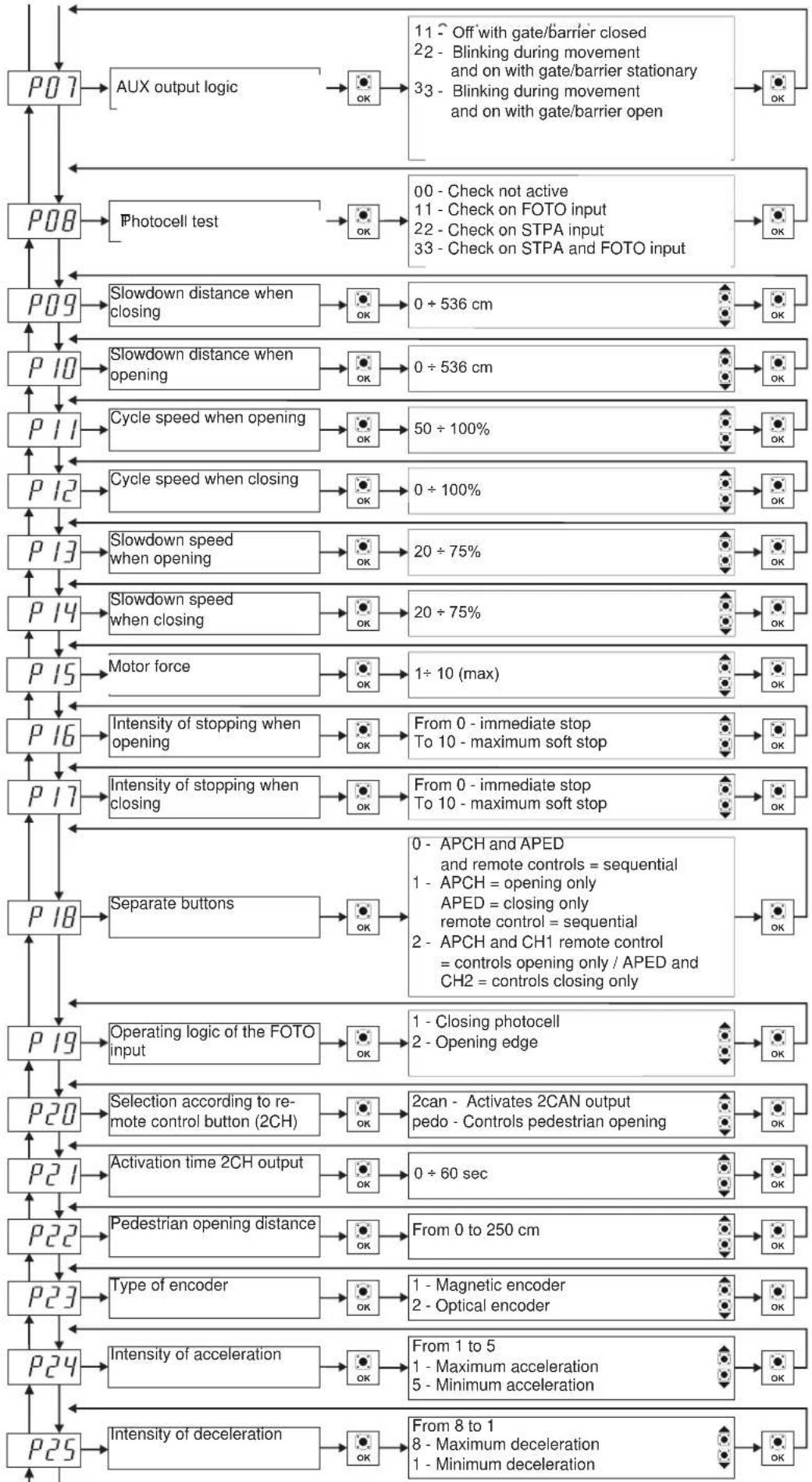
flowchart
graph TD
    A["P07"] --> B["AUX output logic"]
    B --> C["OK"]
    C --> D["11 - Off with gate/barrier closed\n22 - Blinking during movement and on with gate/barrier stationary\n33 - Blinking during movement and on with gate/barrier open"]
    D --> E["OK"]
    F["P08"] --> G["Photocell test"]
    G --> H["OK"]
    H --> I["00 - Check not active\n11 - Check on FOTO input\n22 - Check on STPA input\n33 - Check on STPA and FOTO input"]
    I --> J["OK"]
    K["P09"] --> L["Slowdown distance when closing"]
    L --> M["OK"]
    M --> N["0 ÷ 536 cm"]
    N --> O["OK"]
    P["P10"] --> Q["Slowdown distance when opening"]
    Q --> R["OK"]
    R --> S["0 ÷ 536 cm"]
    S --> T["OK"]
    U["P11"] --> V["Cycle speed when opening"]
    V --> W["OK"]
    W --> X["50 ÷ 100%"]
    X --> Y["OK"]
    Z["P12"] --> AA["Cycle speed when closing"]
    AA --> AB["OK"]
    AB --> AC["0 ÷ 100%"]
    AC --> AD["OK"]
    AE["P13"] --> AF["Slowdown speed when opening"]
    AF --> AG["OK"]
    AG --> AH["20 ÷ 75%"]
    AH --> AI["OK"]
    AJ["P14"] --> AK["Slowdown speed when closing"]
    AK --> AL["OK"]
    AL --> AM["20 ÷ 75%"]
    AM --> AN["OK"]
    AO["P15"] --> AP["Motor force"]
    AP --> AQ["OK"]
    AQ --> AR["1 ÷ 10 (max)"]
    AR --> AS["OK"]
    AT["P16"] --> AU["Intensity of stopping when opening"]
    AU --> AV["OK"]
    AV --> AW["From 0 - immediate stop\nTo 10 - maximum soft stop"]
    AW --> AX["OK"]
    AY["P17"] --> AZ["Intensity of stopping when closing"]
    AZ --> BA["OK"]
    BA --> BB["From 0 - immediate stop\nTo 10 - maximum soft stop"]
    BB --> BC["OK"]
    BD["P18"] --> BE["Separate buttons"]
    BE --> BF["OK"]
    BF --> BG["0 - APCH and APED\nand remote controls = sequential\n1 - APCH = opening only\nAPED = closing only\nremote control = sequential\n2 - APCH and CH1 remote control\n= controls opening only / APED and CH2 = controls closing only"]
    BG --> BH["OK"]
    BI["P19"] --> BJ["Operating logic of the FOTO Input"]
    BJ --> BK["OK"]
    BK --> BL["1 - Closing photocell\n2 - Opening edge"]
    BL --> BM["OK"]
    BN["P20"] --> BO["Selection according to remote control button (2CH)"]
    BO --> BP["OK"]
    BP --> BQ["2can - Activates 2CAN output\npedo - Controls pedestrian opening"]
    BQ --> BR["OK"]
    BS["P21"] --> BT["Activation time 2CH output"]
    BT --> BU["OK"]
    BU --> BV["0 ÷ 60 sec"]
    BV --> BW["OK"]
    BX["P22"] --> BY["Pedestrian opening distance"]
    BY --> BZ["OK"]
    BZ --> CA["From 0 to 250 cm"]
    CA --> CB["OK"]
    CC["P23"] --> CD["Type of encoder"]
    CD --> CE["OK"]
    CE --> CF["1 - Magnetic encoder\n2 - Optical encoder"]
    CF --> CG["OK"]
    DH["P24"] --> DI["Intensity of acceleration"]
    DI --> DJ["OK"]
    DJ --> DK["From 1 to 5\n1 - Maximum acceleration\n5 - Minimum acceleration"]
    DK --> DL["OK"]
    DL --> DM["From 8 to 1\n8 - Maximum deceleration\n1 - Minimum deceleration"]
RS02
flowchart
graph TD
    P26 --> P27
    P27 --> P28
    P28 --> P29
    P29 --> P30
    P30 --> P31
    P31 --> PDEF
    PDEF --> O000
    O000 --> CNT
    CNT --> OK
    OK --> A000
    A000 --> 7000
    7000 --> P000
    P000 --> 1000
    1000 --> Err
    Err --> PASS
    PASS --> ESC
    ESC --> OK
    OK --> P26
    P26 --> Presence["Presence of limit switches"]
    Presence --> OK
    OK --> Off["Off - Limit switches not present"]
    Off --> Op["Op - Opening limit switch only"]
    Op --> Cl-Cl-Closing limit switch only
    Cl-Cl-Closing limit switch only
    APCL-APCL-Opening and closing limit switches present
    APCL-Opening and closing limit switches present --> OK
    OK --> Flashing["Flashing active also with battery"]
    Flashing --> OK
    OK --> On/Off
    On/Off --> OK
    OK --> With["Battery the automation remains open"]
    With --> OK
    OK --> Manned["Manned function"]
    Manned function --> OK
    OK --> Manned2["0 - Operates normally"]
    Manned2 --> 1-1-2-3-4-5-6-7-8-9-10-11-12-13-14-15-16-17-18-19-20-21-22-23-24-25-26-27-28-29-30-31-32-33-34-35-36-37-38-39-40-41-42-43-44-45-46-47-48-49-50-51-52-53-54-55-56-57-58-59-60-61-62-63-64-65-66-67-68-69-70-71-72-73-74-75-76-77-78-79-80-81-82-83-84-85-86-87-88-89-90-91-92-93-94-95-96-97-98-99
    P26 --> Off
    P27 --> Off
    P28 --> Off
    P29 --> Off
    P30 --> Off
    P31 --> Off
    Off --> Manned2
    Manned2 --> Manned3
    Manned3 --> Manned4
    Manned4 --> Manned5
    Manned5 --> Manned6
    Manned6 --> Manned7
    Manned7 --> Manned8
    Manned8 --> Manned9
    Manned9 --> Manned10
    Manned10 --> Manned11
    Manned11 --> Manned12
    Manned12 --> Manned13
    Manned13 --> Manned14
    Manned14 --> Manned15
    Manned15 --> Manned16
    Manned16 --> Manned17
    Manned17 --> Manned18
    Manned18 --> Manned19
    Manned19 --> Manned20
    Manned20 --> Manned21
    Manned21 --> Manned22
    Manned22 --> Manned23
    Manned23 --> Manned24
    Manned24 --> Manned25
    Manned25 --> Manned26
    Manned26 --> Manned27
    Manned27 --> Manned28
    Manned28 --> Manned29
    Manned29 --> Manned30
    Manned30 --> Manned31
    Manned31 --> Manned32
    Manned32 --> Manned33
    Manned33 --> Manned34
    Manned34 --> Manned35
    Manned35 --> Manned36
    Manned36 --> Manned37
    Manned37 --> Manned38
    Manned38 --> Manned39
    Manned39 --> Manned40
    Manned40 --> Manned41
    Manned41 --> Manned42
    Manned42 --> Manned43
    Manned43 --> Manned44
    Manned44 --> Manned45
    Manned45 --> Manned46
    Manned46 --> Manned47
    Manned47 --> Manned48
    Manned48 --> Manned49
    Manned49 --> Manned50
    Manned50 --> Manned51
    Manned51 --> Manned52
    Manned52 --> Manned53
    Manned53 --> Manned54
    Manned54 --> Manned55
    Manned55 --> Manned56
    Manned56 --> Manned57
    Manned57 --> Manned58
    Manned58 --> Manned59
    Manned59 --> Manned60
    Manned60 --> Manned61
    Manned61 --> Manned62
    Manned62 --> Manned63
    Manned63 --> Manned64
    Manned64 --> Manned65
    Manned65 --> MonE["DonE"]

    style P26 fill:#f9f,stroke:#333,stroke-width:2px;
    style P27 fill:#f9f,stroke:#333,stroke-width:2px;
    style P28 fill:#f9f,stroke:#333,stroke-width:2px;
    style P29 fill:#f9f,stroke:#333,stroke-width:2px;
    style P30 fill:#f9f,stroke:#333,stroke-width:2px;
    style P31 fill:#f9f,stroke:#333,stroke-width:2px;

    note right of P26: Per almeno For at least 5 seconds; Return to factory settings (do not delete the saved remote control devices)

    note right of E: Per almeno For at least 5 seconds; Absolute and partial counter (resettable)

    note right of C: Cancellazione dello storico errori o anomalie Delete error or fault log; List of errors or faults

    classDef default fill:#f9f,stroke:#333,stroke-width:1px;
RS02
10 - Installing batteries
Insert the battery charging circuit in the battery card connector and connect the batteries to the circuit, with battery operation the speed of the motor is 15% lower than the speed with mains power, the number of operations with the batteries depends on the number of photocells in the system and the length of the gate/barrier.
11 - Troubleshooting
| Problem Cause Solution | ||
| The automatic gate/barrier system does not work | No mains supplyBlown fusesControl and safety inputs not working | Check the power line switchReplace the fuses with others of the same valueCheck the diagnosis LEDS (STOP, STPA and FOTO must be on) |
| You cannot save the remote controls | Safety devices openBatteries of the remote control dischargedRemote control not compatible with the first one savedReached memory saturation | Check the diagnosis LEDS (STOP, STPA and FOTO must be on)Replace the batteries.The first saved remote control configures the control panel to save only rolling-code remote controls or only dip-switch remote controls.Delete at least one remote control or add an external receiver (maximum capacity 200 remote controls). |
| The remote control does not work Batteries | of the remote control discharged Replace the batteries | |
| You cannot enter travel programming | Safety devices open | Check the diagnosis LEDS (STOP, STPA and FOTO must be on) |
| As soon as the gate/barrier starts it stops and reverses | Low acceleration on starting Decrease the value of parameter 24 | Check the encoder connector is inserted (during gate/barrier movement the enc a and enc b LEDs must be on) |
| During slowdown, the gate/barrier stops and reverses | Slowdown speed too low Increase the value of (parameter 13 and 14) or deceleration too fast (parameter 25) | |
12-Programmable parameters:
Table summarizing the parameters changed during installation
User name remote control association:
| Memory no. User | Memory no. User | Memory no. User | Memory no. User | ||||
| 001 051 | 101 151 | ||||||
| 002 052 | 102 152 | ||||||
| 003 053 | 103 153 | ||||||
| 004 054 | 104 154 | ||||||
| 005 055 | 105 155 | ||||||
| 006 056 | 106 156 | ||||||
| 007 057 | 107 157 | ||||||
| 008 058 | 108 158 | ||||||
| 009 059 | 109 159 | ||||||
| 010 060 | 110 160 | ||||||
| 011 061 | 111 161 | ||||||
| 012 062 | 112 162 | ||||||
| 013 063 | 113 163 | ||||||
| 014 064 | 114 164 | ||||||
| 015 065 | 115 165 | ||||||
| 016 066 | 116 166 | ||||||
| 017 067 | 117 167 | ||||||
| 018 068 | 118 168 | ||||||
| 019 069 | 119 169 | ||||||
| 020 070 | 120 170 | ||||||
| 021 071 | 121 171 | ||||||
| 022 072 | 122 172 | ||||||
| 023 073 | 123 173 | ||||||
| 024 074 | 124 174 | ||||||
| 025 075 | 125 175 | ||||||
| 026 076 | 126 176 | ||||||
| 027 077 | 127 177 | ||||||
| 028 078 | 128 178 | ||||||
| 029 079 | 129 179 | ||||||
| 030 080 | 130 180 | ||||||
| 031 081 | 131 181 | ||||||
| 032 082 | 132 182 | ||||||
| 033 083 | 133 183 | ||||||
| 034 084 | 134 184 | ||||||
| 035 085 | 135 185 | ||||||
| 036 086 | 136 186 | ||||||
| 037 087 | 137 187 | ||||||
| 038 088 | 138 188 | ||||||
| 039 089 | 139 189 | ||||||
| 040 090 | 140 190 | ||||||
| 041 091 | 141 191 | ||||||
| 042 092 | 142 192 | ||||||
| 043 093 | 143 193 | ||||||
| 044 094 | 144 194 | ||||||
| 045 095 | 145 195 | ||||||
| 046 096 | 146 196 | ||||||
| 047 097 | 147 197 | ||||||
| 048 098 | 148 198 | ||||||
| 049 099 | 149 199 | ||||||
| 050 100 | 150 200 |
RS02
13 - INSTALLING THE CARD ON THE 12V SLIDING ACTUATORS WITH OPTICAL ENCODER
Connecting the electric motor:
| Terminal board Mocable colour | |
| 1 (APM1) Red | |
| 2 (CHM1) Black | |
Connecting the limit stop sensor:
| Terminal board Sensor cable colour | |
| 17 (FCAP) Brown | |
| 18 (COM1) Blue | |
| 19 (FCCH) Black | |
Connecting the encoder:
| Terminal board Encoder cable colour | |
| SE White | |
| -E Blue | |
| +E Brown | |
Adjusting the opening direction:
as described in paragraph 6, the opening direction is adjusted by parameter P31:
P31 = OFF, opening to the left (default)
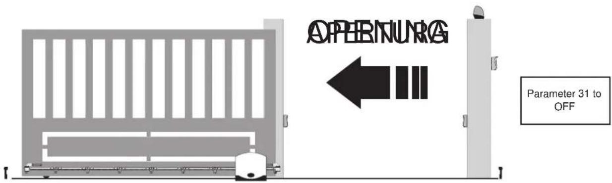
P31 = ON, opening to the right
EC DECLARATION OF CONFORMITY
(Declaration of incorporation of partly completed machinery Annex IIB Directive 2006/42/EC)
No.:ZDT00434.00
The undersigned, representing the following manufacturer
Elvox SpA
Via Pontarola, 14/A - 35011 Campodarsego
(PD) Italy
herewith declares that the products
CONTROL BOARD - RS SERIES
Articles RS01, RS02, RS03, RS04, RS05, RS06, RS07, RS08, RS12, RS13, RS14
are in conformity with the provisions of the following EU Directive(s) (including all applicable amendments) and that all of the following standards and/or specifications have been applied
EMC Directive 2004/108/EC: EN 61000-6-1 (2007), EN 61000-6-3 (2007) + A1 (2011)
R&TTE Directive 1999/5/EC: EN 301 489-3 (2002), EN 300 220-3 (2000)
Machinery Directive 2006/42/EC EN 60335-2-103 (2003) + A11 (2009), EN 13241 (2003) + A1 (2011), EN 12453 (2000)
He also declares that the product must not be commissioned until the end machine, in which it is to be incorporated, has been declared in conformity, when applicable, with the provisions of Directive 2006/42/EC.
He declares that the relevant technical documentation has been constituted by Elvox SpA, drawn up in accordance with Annex VIIB of Directive 2006/42/EC and that the following essential requirements have been fulfilled: 1.1.1, 1.1.2, 1.1.3, 1.1.5, 1.1.6, 1.2.1, 1.2.2, 1.2.6, 1.3.1, 1.3.2, 1.3.3, 1.3.4, 1.3.7, 1.3.8, 1.3.9, 1.4.1, 1.4.2, 1.5.1, 1.5.2, 1.5.4, 1.5.5, 1.5.6, 1.5.7, 1.5.8, 1.5.9, 1.6.1., 1.6.2, 1.7.1, 1.7.2, 1.7.3, 1.7.4.
He undertakes, in response to an adequately justified request from the national authorities, to present all the necessary supporting documentation concerning the product.
Campodarsego, 29/04/2013
The Chief Executive Officer
Note: The contents of this declaration match what was declared in the latest revision of the official declaration that was available before this manual was printed. This text has been adapted for editorial purposes. A copy of the original declaration can be requested from Elvox SpA
RS02
Index Page
natural_image
Diagram showing a beam passing through a vertical prism with an arrow indicating direction (no text or symbols)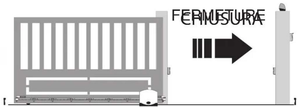
RS02


RS02
DÉCLARATION DE CONFORMITÉ
articles RS01, RS02, RS03, RS04, RS05, RS06, RS07, RS08, RS12, RS13, RS14
natural_image
Diagram showing a beam with an arc and a dashed line, no text or symbols present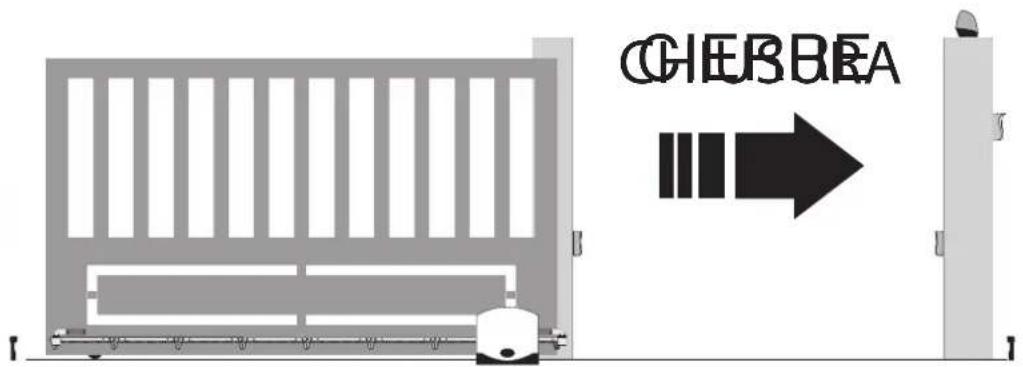

RS02


RS02
natural_image
Diagram showing a beam being tilted at an angle with an arrow indicating direction (no text or symbols)
natural_image
Diagram showing a beam passing through a rectangular block with an arrow indicating direction (no text or symbols)
RS02


RS02
flowchart
graph TD
    A["Start: Screen icon, AP/CH, BSC, x4"] --> B["Arrow pointing to 'x4'"]
    B --> C["Pattern: Screen icon, AP/CH, BSC, OK"]
    C --> D["Arrow pointing to 'P01'"]
    D --> E["Arrow pointing to 'P01', BSC, OK"]
    E --> F["Arrow pointing to 'on'"]
    F --> G["Arrow pointing to 'on', BSC, OK"]
    G --> H["Arrow pointing to 'off'"]
    H --> I["Arrow pointing to 'off', BSC, OK"]
    I --> J["Down arrow: Taste changes from 'P01' to 'OFF'"]
    J --> K["Legend: ▲ = Color, ● = Pattern"]
    style A fill:#f9f,stroke:#333
    style B fill:#ccf,stroke:#333
    style C fill:#cfc,stroke:#333
    style D fill:#fcc,stroke:#333
    style E fill:#cff,stroke:#333
    style F fill:#ffc,stroke:#333
    style G fill:#cfc,stroke:#333
    style H fill:#fcc,stroke:#333
    style I fill:#cfc,stroke:#333
    style J fill:#fcc,stroke:#333
    style K fill:#cfc,stroke:#333
Parametertabelle
Eik. 1
Λεζάντα:


RS02
RS01, RS02, RS03, RS04, RS05, RS06, RS07, RS08, RS12, RS13, RS14


- RS02
- Warnings for the installer
- Directive 2002/96/EC (WEEE).
- Risks associated with substances considered hazardous (WEEE).
- CE
- 1- Characteristics
- Key:
- 3- Risk assessment
- 4- Electrical wiring harnesses
- 4.1- Power supply line wiring
- 4.2- Wiring for flashing light, courtesy light and gate/barrier movement warning light
- Input description table:
- 4.3- Connecting control buttons and key switch
- 4.4- Connecting photocells
- 4.5- Sensitive edge connection
- Connecting internal photocell
- Connecting photocells with photo-test function active
- 4.7- Stop button connection
- 4.8- Connecting the aerial
- Preliminary check:
- - Set the type of actuator
- 7- Quick programming
- Procedure for saving a remote control associated with button APCH:
- Example of the procedure for changing the automatic closing time:
- 8- Full description of the programming menu.
- LRNE: quick procedure for programming gate/barrier travel
- RAD: remote control management menu is divided into 4 parameters:
- Description of RAD menu parameters:
- Display
- Message
- N.B. The first saved remote control configures the control panel to accept only remote controls with a rolling code or only remote controls with a fixed 12-bit code
- LRN: Learning travel with custom programming lets you define the points for starting deceleration when both opening and closing:
- - Installing batteries
- 12-Programmable parameters:
- - INSTALLING THE CARD ON THE 12V SLIDING ACTUATORS WITH OPTICAL ENCODER
- EC DECLARATION OF CONFORMITY
- CONTROL BOARD - RS SERIES
- The Chief Executive Officer
- Index Page
- DÉCLARATION DE CONFORMITÉ
- Λεζάντα:
Brand : Vimar
Model : ELVOX RA98
Category : Gate automation