
ELVOX ESM4 - Gate automation Vimar - Free user manual and instructions
Find the device manual for free ELVOX ESM4 Vimar in PDF.

| Brand | Vimar |
| Model | ELVOX ESM4 (series RS09/RS09.120) |
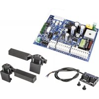
| Product type | Control board for sliding motor gearboxes |
| Power supply | 230/120 Vac, 50/60 Hz |
| Max motor power | 600 W |
| 24 Vdc output | 300 mA for accessories (photocells, etc.) |
| Radio receiver capacity | 128 remote controls (fixed or rolling code) |
| Safety inputs | STOP (NC), FOTO (NC), STPA (NC/resistive/switch) |
| Control inputs | APCH (sequential), APED (pedestrians), APRI (partial opening) |
| Limit switches | FCAP (opening), FCCH (closing), normally closed |
| Programmable functions | Travel, slowdown, operating logics (condominium, automatic, step-by-step, etc.) |
| Adjustments | Trimmers: Pause (1-140s), Power (20-100%), Brake (0-100%), Slowdown speed (30-100%), Sensitivity (obstacle detection) |
| Protection | Fuse F1 (630 mA) for logic, F2 (5 A) for motor |
| LED indicators | Input diagnostics (APRI, APCH, APED, STOP, FOTO, STPA, FCAP, FCCH, DL9) |
| Compliance | Directives LV, EMC, R&TTE, Machinery (2006/42/EC) |
| Included accessories | Rigid wire antenna 17 cm, encoder connector (optional) |
Frequently Asked Questions - ELVOX ESM4 Vimar
User questions about ELVOX ESM4 Vimar
0 question about this device. Answer the ones you know or ask your own.
Ask a new question about this device
Download the instructions for your Gate automation in PDF format for free! Find your manual ELVOX ESM4 - Vimar and take your electronic device back in hand. On this page are published all the documents necessary for the use of your device. ELVOX ESM4 by Vimar.
USER MANUAL ELVOX ESM4 Vimar
Board with 230/120 Vac trimmer for sliding gate
natural_image
Pure electrical circuit lines without any symbolsFig. 12
1 - Characteristics....11
2 - Description 11
3- Electrical wiring harnesses....12
4- Description of the LEDS in the circuit....16
5- Description of the buttons in the circuit....16
6 - Programming....17
7- Trimmer for adjustments....18
8- Dip switch functions 19
9 - Troubleshooting....20
1- Characteristics
Control panel for governing sliding gear motors, 230/120 Vac with 600 W rated power, equipped with inputs for limit switch, encoder (used for obstacle detection and speed control) and integrated receiver. The control panel enables:
- customizing the space and speed of deceleration in both opening and closing phases
- equipped with an obstacle detection system (if there is an encoder circuit)
- LED for input diagnostics
- removable data memory
- integrated receiver with capacity for 128 remote control codes (hard coded or rolling code)
2- Description
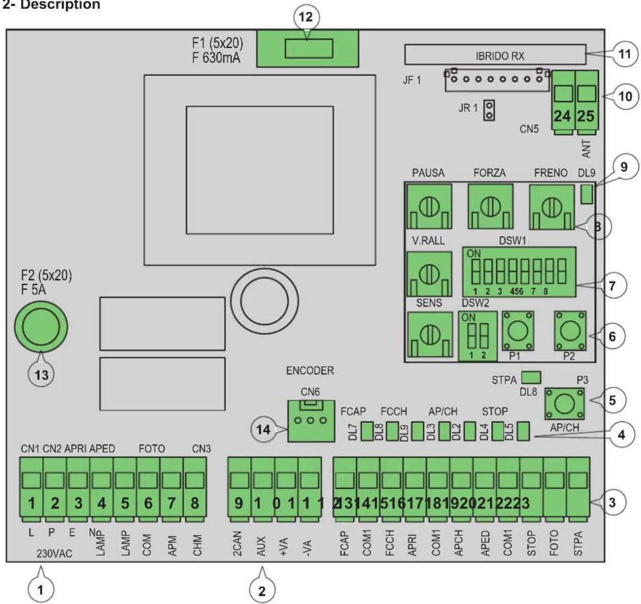
Fig. 1
Key:
1- Removable terminal for the power line, flashing light and electric motor
2- Removable terminal for 24 Vdc outputs
3- Removable terminal for safety and control inputs
4- LED for input diagnostics
5- APCH control sequential button
6- Buttons for programming the travel and remote controls
7- Dip switches for programming functions
8- Trimmer for adjustments
9- LED for programming diagnostics
10- Removable aerial connector
11- Radio module
12- Protection fuse for 24 V output and control logic (630 mA)
13- Protection fuse for motor output, transformer and flashing light (5 A)
14- Encoder connector
3 - Electrical wiring harnesses:
System set-up
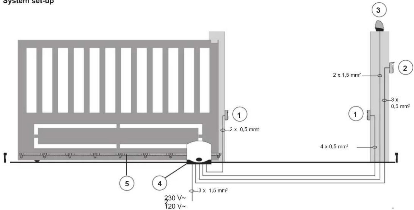
Key:
1 - Photocells
2 - Selector switch
3 - Flashing light
4 - Gear motor
5 - Rack
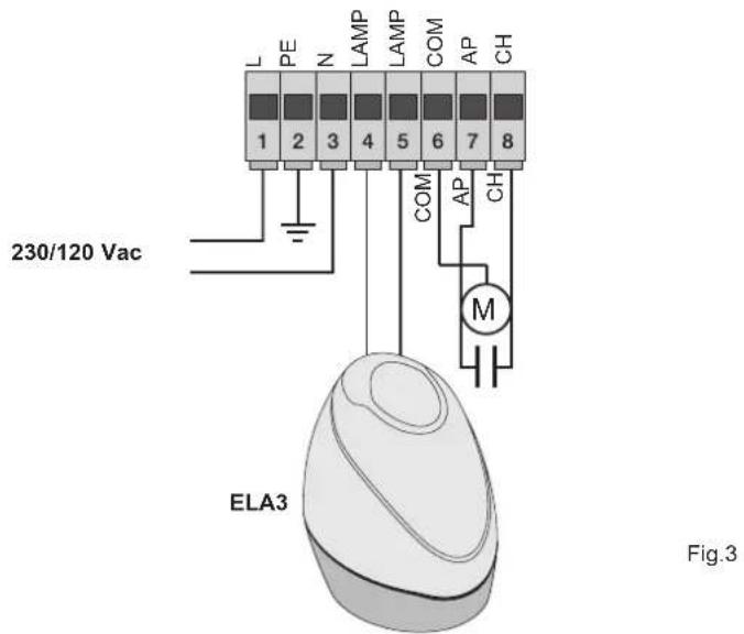
3.1- Wiring for power line, flashing light and electric motor:
3.2- Wiring for 24V outputs:

| Terminal number | Description Function | |
| 1-2-3 | Power supply line | 230/120 Vac power line (1 = phase / 2 = ground wire / 3 = neutral) |
| 4-5 | Output for flashing light | Output for flashing light (230/120 Vac max 60 Watt) |
| 6-7-8 | Output for powering the electric motor | Output for powering the electric motor (6 = common / 7 = opens / 8 = closes) the capacitor is connected in terminal 7 and 8 in parallel with the electric motor |
| 9-11 | Second radio channel or photo-test output | Second radio channel or photo-test output (can be selected with dip switch 1-3 and 9 = GND / 11= +24 Vdc max 120 mA) |
| 10-11 | Gate movement warning output | Gate movement warning output (10 = GND / 11 = +24 Vdc max 120 mA) |
| 11-12 | 24 Vdc output | 24 Vdc output to power photocells and accessories (11 = GND / 12 = +24 Vdc 300mA) |
The sum of the absorptions of the 2CAN, AUX and -VA outputs must not exceed 500 mA
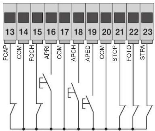
3.3- Input wiring:
The control panel is supplied with non-jumpered normally closed safety inputs (STOP, FOTO, STPA), add a jumper between the common (COM) and input you do not intend to use
RS09/RS09.120
| Terminal number | Description Input type | |
| 14-17-20 Control inputs common (permanent GND) - | ||
| 13 Opening limit switch input (with dip switch 2-1 OFF) Normally closed | ||
| 15 Closing limit switch input (with dip switch 2-1 OFF) Normally closed | ||
| 16 | Opening-only button input, dedicated for timer or detector for magnetic induction coils | Normally open |
| 18 Sequential control input, to govern the complete travel of the gate Normally open | ||
| 19 Sequential control input, to govern the pedestrian travel of the gate Normally open | ||
| 21 Input for stopping the gate | Normally closed | |
| 22 | Photocell input, active during gate closing | Normally closed |
| 23 | Input for edges or internal photocell, active during gate closing and opening | Normally closed |
3.4- Connecting control buttons and key switch, normally open contacts (the ap/ch or aped LEDs come on when the selector or the buttons connected in parallel are operated) the APCH input controls opening or closing the gate completely, the APED input controls partial gate opening or closing:
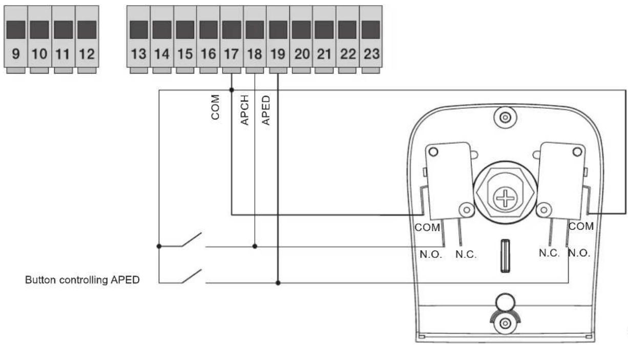
Fig. 6
3.5- Connection of timer or detector with magnetic induction with normally open contact (the open LED comes on when the timer or magnetic induction detector are operated) the OPEN input commands full opening of the gate, until the contact is closed, the gate opens and remains in the open position, the APCH, APED commands and saved remote controls are not active until the contact is reset from closed to open, after the automatic closing time set with the PAUSE trimmer, the gate closes, this input is used to open and hold open the gate at the times of greatest influx:
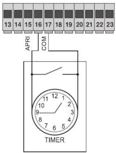
Fig. 7
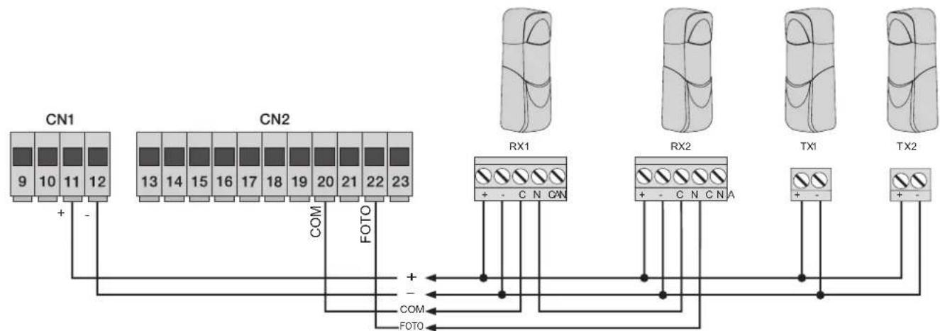
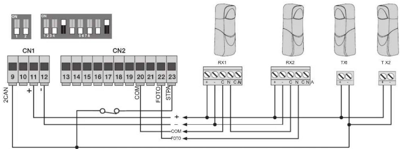
3.6- Connecting photocells:
Normally closed contact (when the photocells are not engaged the PHOTO LED must be on), when this input trips during closing it reverses the movement, if not used then jumper between COM and PHOTO, you must observe the polarity of the power supply for the photocells:
flowchart
graph TD
    A["CN1"] -->|+ -| B["CN2"]
    B -->|COM FOTO| C["RX1"]
    C -->|+ -| D["RX2"]
    D -->|+ -| E["TX1"]
    E -->|+ -| F["TX2"]
    style A fill:#f9f,stroke:#333
    style B fill:#f9f,stroke:#333
    style C fill:#ccf,stroke:#333
    style D fill:#ccf,stroke:#333
    style E fill:#ccf,stroke:#333
    style F fill:#ccf,stroke:#333
Fig. 8
3.7- Sensitive edge connection
Programmable input (with the edge or photocell not engaged, the STPA LED must be on) if this input trips during opening it immediately reverses the movement for 1.5 seconds and then stops the gate, while during closure it reverses the movement until fully open, see the dip switch 1-4 to select the type of edge. If not used jumper between COM. and STPA and set the dip switch 1-4 off:
Resistive sensitive edge connection
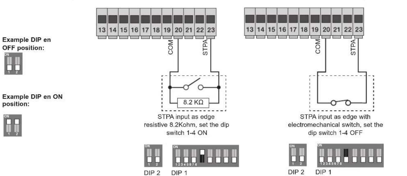
Switch edge connection
3.8- Electrical connection with photo-test function active (dip switch 1-3 and 1-8 ON) the control unit governs the operation of the safety devices.
flowchart
graph TD
    subgraph CAN
        A["CN1 9"] -->|+| B["CN2 13"]
        C["CN1 10"] -->|+| B
        D["CN1 11"] -->|+| B
        E["CN1 12"] -->|+| B
    end
    subgraph CN2
        F["CN2 13"] --> G["CN2 14"]
        H["CN2 15"] --> I["CN2 16"]
        J["CN2 17"] --> K["CN2 18"]
        L["CN2 19"] --> M["CN2 20"]
        N["CN2 21"] --> O["CN2 22"]
        P["CN2 23"] --> Q["STPA COM"]
        R["FOTO"] --> S["FOTO"]
    end
    subgraph RX1
        T["RX1 + -"] --> U["CNCAN"]
        V["RX1 + -"] --> W["CNCAN"]
        X["RX1 + -"] --> Y["CNCAN"]
        Z["RX1 + -"] --> AA["CNCAN"]
        AB["RX2 + -"] --> AC["CNCAN"]
        AD["RX2 + -"] --> AE["CNCAN"]
        AF["TX1 + -"] --> AG["CNCAN"]
        AH["TX1 + -"] --> AI["CNCAN"]
    end
    subgraph RX2
        AJ["RX2 + -"] --> AK["CNCAN"]
        AL["RX2 + -"] --> AM["CNCAN"]
        AN["RX2 + -"] --> AO["CNCAN"]
        AP["TX1 + -"] --> AQ["CNCAN"]
        AR["TX1 + -"] --> AS["CNCAN"]
    end
    subgraph TX2
        AT["TX2 + -"] --> AU["CNCAN"]
        AV["TX2 + -"] --> AW["CNCAN"]
    end
3.9- Stop button connection: normally closed contact, opening the contact causes the gate to stop and suspends the automatic closing time (when the button is not engaged, the STOP LED should be lit), if not used then jumper between COM and STOP:
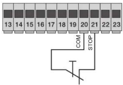
Normally closed button
Fig. 11
N.B. If the system has no photocells, sensitive edges or stop buttons, the PHOTO, STPA and STOP inputs must be jumpered (do not activate the photo-test function and select the switch edge, dip switch 1.4 and 1.8 set OFF).
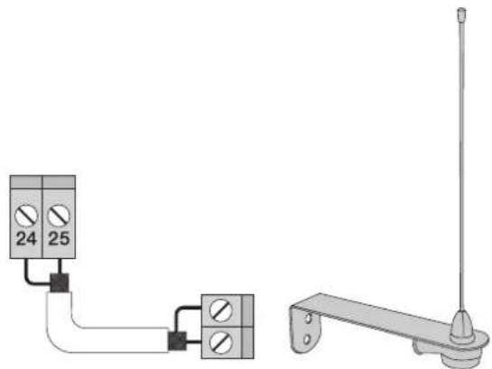
3.10- Connecting the aerial:
The 17cm rod is supplied pre-wired, to increase the range connect the aerial as shown in the figure:
natural_image
Pure electrical circuit lines without any symbolsFig. 12
4 - Description of the LEDS in the circuit:
| ABBREVIATION DESCRIPTION | |
| OPEN | Displays the status of the OPEN input (terminal number 16), if not engaged the red LED stays off (used to control opening only, dedicated for the magnetic induction coil connection or timer) |
| AP/CH | Displays the status of the AP/CH input (terminal number 18), if not engaged the red LED remains off |
| APED | Displays the status of the APED input (terminal number 19), if not engaged the red LED remains off |
| STOP | Displays the status of the STOP input (terminal number 21), if not engaged the green LED remains lit, if not used then jumper between terminal COM and STOP |
| PHOTO | Displays the status of the PHOTO input (terminal number 22), if not engaged the green LED remains lit, if not used then jumper between terminal COM and PHOTO. |
| STPA | Displays the status of the STPA input (terminal number 23), if not engaged the green LED remains lit, if not used then jumper between terminal COM and STPA. |
| FCAP | Displays the input of the opening limit switch, it turns off when the gate is fully open, if the dip-switch 2.1 is set to OFF |
| FCCH | Displays the input of the closing limit switch, it turns off when the gate is fully closed, if the dip-switch 2.1 is set to OFF |
| DL9 | Displays the programming status |
5 - Buttons in the circuit:
| Abbreviation Description |
| AP/CH Controls opening and closing the gate |
| P1 Press to enter travel programming |
| P2 Press to enter radio controls programming or deletion |
Preliminary check:
After powering up the control unit the DL9 LED comes on for a second. Check the diagnostic LEDs of the inputs, STOP, PHOTO, STPA, FCAP and FCCH must be on, if one of the normally closed contacts or one of the normally open contacts is not in the rest state, the DL9 LED flashes quickly to indicate a fault.
Should one of the safety inputs (PHOTO, STOP, STPA) not be used, insert a jumper between COM and the input not used.
6 - Programming
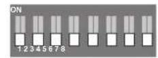
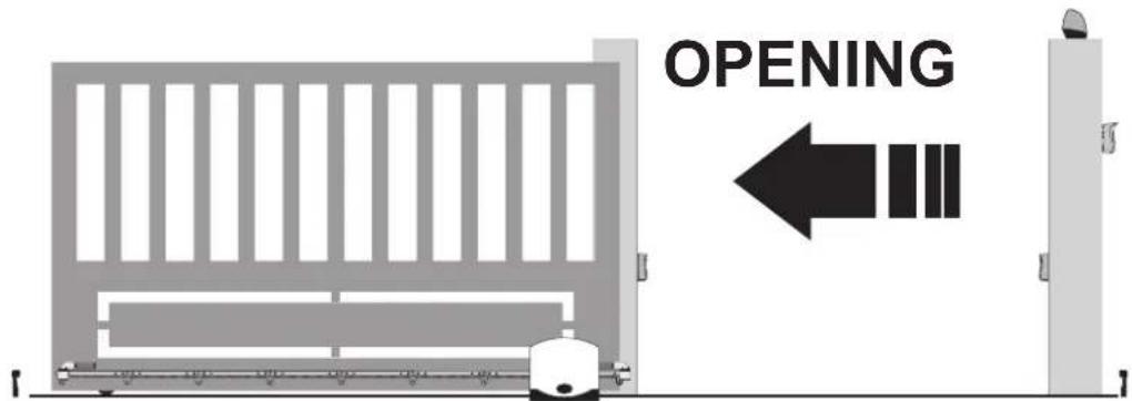
Selecting the direction of opening: the control unit is equipped with dip switches to select the direction of gate opening. If the gate opens to the right, set the dip switch 2-1 OFF:
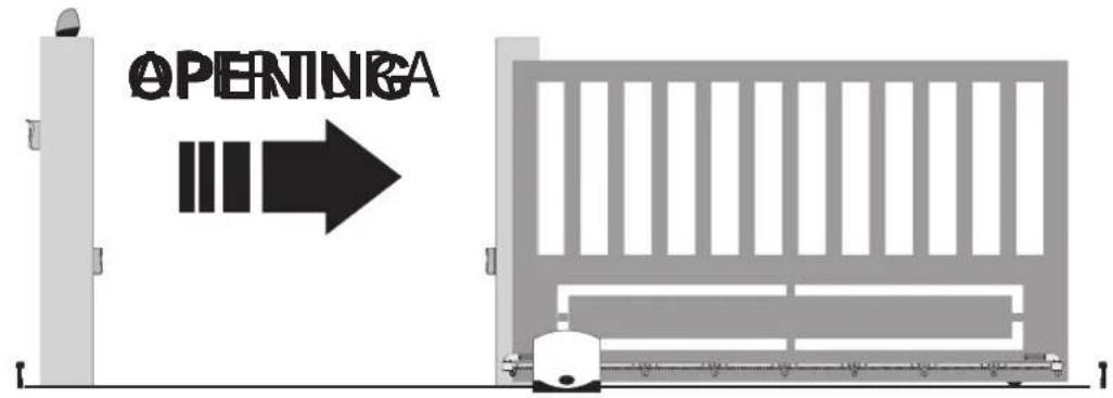

DIP 2
DIP 1
If the gate opens to the left, set the dip switch 2-1 ON:

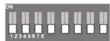
DIP 2
DIP 1
Procedure for gate travel programming:
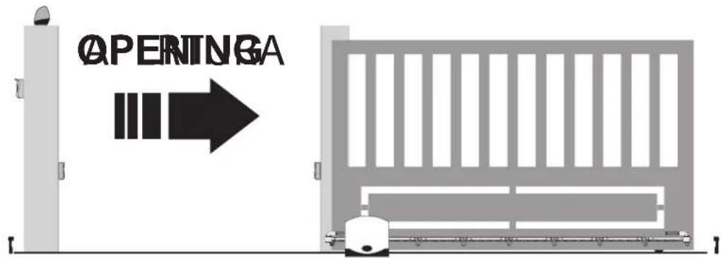
Fig. 13
- Move the gate into the closed position, the limit switch LED must be off
- Press and hold down the P1 button until the red DL9 LED starts flashing, approximately 3 seconds
- Press and release the AP/CH button, the gate starts opening at normal speed
- Press and release the AP/CH button, to fix the starting point of deceleration on opening, the gate continues at reduced speed until the opening limit switch trips, to then stop
- After approximately 2 seconds, it automatically starts closing at normal speed
- Press and release the AP/CH button, to fix the starting point of deceleration on closing, the gate continues at reduced speed until the closing limit switch trips, to then stop
- After approximately 2 seconds, it automatically starts opening at normal speed
- Press and release the AP/CH button, to fix the point of partial or pedestrian opening
- After approximately 2 seconds, it automatically starts closing at normal speed until the closing limit switch trips, to then stop.
The DL9 LED turns off to indicate that the travel programming is over.
RS09/RS09.120
If the gate movement turns out to be reversed, check the dip switch 2-1, do not change the wiring or the limit switch or the electric motor.
Programming and deleting the remote control.
The first saved remote control sets the type of remote controls that can be used (rolling code or hard code)
programming the button of the remote control associated with the AP/CH input:
- Press and hold down the P2 button until the DL9 LED starts flashing slowly, release button P2
- Press the button of the remote control to save as the full gate opening and closing command, within 10 seconds
- The DL9 LED comes on with a steady light for 2 seconds and then goes out, the remote control is saved, to save other remote controls, repeat the above procedure.
Programming the button of the remote control associated with the APED input or 2CAN output (see dip switch number 3):
- Press and hold down the P2 button until the DL9 LED starts flashing quickly, for approximately 4 seconds, release button P2
- Press the button of the remote control to save as the pedestrian gate opening command or 2CAN output activation, within 10 seconds
- The DL9 LED comes on with a steady light for 2 seconds and then goes out, the remote control is saved, to save other remote controls, repeat the above procedure.
Deleting all the saved remote controls:
Switch off the power supply to the control panel. Press and hold down button P2, switch back on the power supply to the control panel without releasing button P2. Led DL9 starts to flash, the flashing speed then increases, when led DL9 goes out release button P2.
At the end of this procedure all the remote controls in memory are deleted, the first remote control that will be learned sets the type of remote controls that can be saved in the control panel.
The maximum capacity is 128 remote controls, on reaching the maximum capacity, when entering remote control programming (the DL9 LED flashes) on pressing the button of the new transmitter to be saved, the DL9 LED makes three quick flashes.
Saving the settings:
You can save the current setting of the dip switches and trimmers on the removable board and then remove it, in order to make further changes impossible. Proceed as follows: press buttons P1 and P2 simultaneously until the DL9 LED lights up, release the buttons, the DL9 LED will flash quickly and then go out. You can now remove the card and the settings of the dip switches and trimmers will be retained even after switching the control unit off and back on again.
Testing the automatic gate system:
It is necessary to test all the accessories connected to the control unit, especially the safety devices such as the sensitive edges and photocells. Remember that the photocells reverse the movement of the gate only during closure and, when pressed during opening, the sensitive edges reverse the movement of the gate for 1.5 seconds, while if pressed when closing they fully re-open the gate.
7 - Trimmer for adjustments:
| Trimmer Function Range | ||
| Pause Automatic closing time From 1 to 140 seconds maximum clockwise | ||
| Force Motor force From 20 to 100%, maximum, clockwise | ||
| Brake | Braking on limit switch | From 0 to 100% (when zero, braking is not active), maximum, clockwise |
| Sldwn.sp. Slow down speed From 30 to 100%, maximum, clockwise | ||
| Sens. | Time for obstacle detection | If this trimmer is set on the maximum, the anti-crushing function is not active |
RS09/RS09.120
8 - Dip switch functions: After setting the dip switches it is necessary to jumper the jr1 reset contacts for a few seconds or switch power off and back on again for the change to be updated by the control panel:
| Dip switch number | Status of dip switch Description | |
| DIP 1-1 OFF Pick-up on starting ON | ||
| DIP 1-1 ON Pick-up on starting OFF | ||
| DIP 1-2 OFF Pre-flashing off | ||
| DIP 1-2 | ON | Pre-flashing on, before the gate moves the flashing light comes on for 3 seconds |
| DIP 1-3 | OFF | The 2CAN output is associated with the second channel of the remote control |
| DIP 1-3 ON The | 2CAN output is used to feed the photocell transmitters | |
| DIP 1-4 | OFF | The STPA input used for the switch sensitive edge connection |
| DIP 1-4 | ON | The STPA input used for the resistive sensitive edge connection |
| DIP 1-5 OFF | See table for control input operating logic | |
| DIP 1-5 ON | ||
| DIP 1-6 OFF | ||
| DIP 1-6 ON | ||
| DIP 1-7 OFF | ||
| DIP 1-7 ON | ||
| DIP 1-8 OFF Photo-test function off | ||
| DIP 1-8 | ON | Photo-test function on (photocell checking with each command) see paragraph 4.8 |
| DIP 2-1 OFF For opening the gate to the right | ||
| DIP 2-1 ON For opening the gate to the left | ||
| DIP 2-2 OFF | The AUX output (terminal number 10) flashes during the gate movement, slowly flashing when opening, quickly during closing, on steady when the gate is open and off when the gate is closed | |
| DIP 2-2 | ON | The AUX output (terminal number 10) is switched off only when the gate is fully closed |
Control input operating logic:
| Dip 5 | Dip 6 | Dip 7 | Logic |
| OFF | OFF | OFF | Condominium plus |
| OFF | OFF | ON | Condominium plus+ close immediately |
| OFF ON | OFF | Automatic | |
| OFF | ON | ON | Automatic+ close immediately |
| ON | ON | OFF | condominium |
| ON | ON | ON | Condominium + close immediately |
| ON OFF | OFF | Semi-automatic | |
| ON OFF | ON | Step-by-step |
Logic description:
Condominium plus: when the gate is closed the APCH command controls opening, during the opening phase it is ignored. Once opening has completed the gate is paused for the rest time. During the pause time an APCH command makes the automatic closing time restart from scratch. During closing the APCH command controls reopening.
Automatic: when the gate is closed the APCH command controls opening, during the opening phase it stops the gate and with an additional command the gate closes. In the case of complete opening, the gate is paused for the rest time. During the pause time an APCH command makes the gate restart with closing. During closing the APCH command controls reopening.
Condominium: with the gate closed an APCH input command controls opening, during gate opening the APCH command is ignored by the control unit, with the gate fully open it stays open for the automatic closing time. With an APCH command during the pause the gate starts to close, an additional command during closing controls reopening.
Semi-automatic: with the gate closed an APCH input command controls opening. During opening the APCH command stops the gate. When the gate is fully open and automatic closing is not active, to close the gate before the automatic closing time you need to apply a command via the APCH input, another APCH command during closing controls reopening.
Step-by-step: with the gate closed an APCH input command controls opening. During opening the APCH command stops the gate. When the gate is fully open, automatic closing is not active, to close the gate you need to apply a command via the APCH input, another APCH command during closing stops the gate and another pulse causes reopening.
Close immediately: engaging the photocells causes the gate to close 5 seconds after they are disengaged, regardless of the set rest time.
The control panel can work with or without an encoder. When switching on, the control unit checks for the presence of the encoder on connector CN6. For operation without an encoder it is necessary to insert the jumper in connector CN6 as shown in the image fig.15 and power up the control panel. With this configuration, the SENS trimmer and the obstacle detection function are not active. For operation with an encoder it is necessary to insert the encoder circuit cable in connector CN6 and power up the control panel. With this configuration, the SENS trimmer and the obstacle detection function are active.
Operation with an encoder:
| Obstacle detection Description |
| During closing The gate immediately reverses its movement, to open completely |
| During opening The gate immediately reverses its movement for 1.5 seconds to then stop |
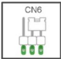
Fig. 14
9 - Troubleshooting:
| Problem Cause Solution | ||
| The automatic gate system does not work No mains supply | Blown fusesControl and safety inputs not working | Check the power line switchReplace the fuses with others of the same valueCheck the diagnosis leds (STOP, STPA and PHOTO must be on) |
| You cannot save the remote controls Safety devices open | Batteries of the remote control dischargedRemote control not compatible with the first one savedReached memory saturation | Check the diagnosis leds (STOP, STPA and PHOTO must be on)Replace the batteriesThe first saved remote control configures the control panel to save only rolling-code remote controls or only dip-switch remote controlsDelete at least one remote control or add an external receiver (maximum capacity 128 remote controls) |
| The remote control does not work Batteries of the remote control discharged Replace the batteries | ||
| You cannot enter travel programming Safety devices open Check the diagnosis leds (STOP, STPA and PHOTO must be on) | ||
| As soon as the gate starts it stops and reverses Low acceleration on startingEncoder not detected | Increase the FORCE and SENS trimmerCheck the encoder connector is plugged in | |
| During slowdown, the gate stops and reverses Slowdown speed too low Increase the Sldwn.sp. and Sens trimmer | ||
| The gate does not stop with the limit switches tripping and obstacle detection trips | The limit switch does not work properly | Advance the limit switch bracket |
EC DECLARATION OF CONFORMITY
(Declaration of incorporation of partly completed machinery Annex IIB Directive 2006/42/EC)
No.: ZDT00438.00
The undersigned, representing the following manufacturer
Elvox SpA
Via Pontarola, 14/A - 35011 Campodarsego
(PD) Italy
herewith declares that the products
CONTROL BOARD - RS SERIES
Articles RS09, RS10, RS11, RS15
are in conformity with the provisions of the following EU Directive(s) (including all applicable amendments) and that all of the following standards and/or specifications have been applied
LV Directive 2006/95/EC: EN 60335-2-103 (2003) + A11 (2009)
EMC Directive 2004/108/EC: EN 61000-6-1 (2007), EN 61000-6-3 (2007) + A1 (2011)
EN 61000-6-2 (2005), EN 61000-6-4 (2007) + A1 (2011)
R&TTE Directive 1999/5/EC: EN 301 489-3 (2002), EN 300 220-3 (2000)
Machinery Directive 2006/42/EC EN 13241(2003) + A1 (2011), EN 12453 (2000)
He also declares that the product must not be commissioned until the end machine, in which it is to be incorporated, has been declared in conformity, when applicable, with the provisions of Directive 2006/42/EC.
He declares that the relevant technical documentation has been constituted by Elvox SpA, drawn up in accordance with Annex VIIB of Directive 2006/42/EC and that the following essential requirements have been fulfilled: 1.1.1, 1.1.2, 1.1.3, 1.1.5, 1.1.6, 1.2.1, 1.2.2, 1.2.6, 1.3.1, 1.3.2, 1.3.3, 1.3.4, 1.3.7, 1.3.8, 1.3.9, 1.4.1, 1.4.2, 1.5.1, 1.5.2, 1.5.4, 1.5.5, 1.5.6, 1.5.7, 1.5.8, 1.5.9, 1.6.1., 1.6.2, 1.7.1, 1.7.2, 1.7.3, 1.7.4.
He undertakes, in response to an adequately justified request from the national authorities, to present all the necessary supporting documentation concerning the product.
Campodarsego, 29/04/2013
The Chief Executive Officer
Note: The contents of this declaration match what was declared in the latest revision of the official declaration that was available before this manual was printed. This text has been adapted for editorial purposes. A copy of the original declaration can be required to Elvox SpA.
RS09/RS09.120
Index Page
natural_image
Pure electrical circuit lines without any symbolsFig. 12
DÉCLARATION DE CONFORMITÉ
natural_image
Pure electrical circuit lines without any symbolsFig. 12
natural_image
Pure electrical circuit lines without any symbolsAbb. 13
natural_image
Pure electrical circuit lines without any symbolsEik. 13

- 1- Characteristics
- Key:
- - Electrical wiring harnesses:
- 3.1- Wiring for power line, flashing light and electric motor:
- 3.2- Wiring for 24V outputs:
- 3.3- Input wiring:
- 3.6- Connecting photocells:
- 3.7- Sensitive edge connection
- 3.10- Connecting the aerial:
- Preliminary check:
- - Programming
- RS09/RS09.120
- Deleting all the saved remote controls:
- Saving the settings:
- Testing the automatic gate system:
- - Trimmer for adjustments:
- Logic description:
- EC DECLARATION OF CONFORMITY
- (Declaration of incorporation of partly completed machinery Annex IIB Directive 2006/42/EC)
- CONTROL BOARD - RS SERIES
- The Chief Executive Officer
- Index Page
- DÉCLARATION DE CONFORMITÉ
Brand : Vimar
Model : ELVOX ESM4
Category : Gate automation