
ELVOX EAM9.L - Gate automation Vimar - Free user manual and instructions
Find the device manual for free ELVOX EAM9.L Vimar in PDF.

| Product type | Linear actuator for swinging gates |
| Brand | Vimar (Elvox) |
| Model | ELVOX EAM9.L |
| Power supply | 230 VAC, 50/60 Hz |
| Max motor absorption | 1.1 A |
| Max motor power | 240 W |
| Max thrust | 2800 N |
| Max leaf length | 4 m |
| Max leaf weight | 200 kg |
| Max opening | 110 ° |
| Opening time | 16 to 27 seconds |
| Protection rating | IP54 |
| Operating temperature | -20 °C to +50 °C |
| Duty cycle | 50 % |
| Usable stroke | 400 mm |
| Actuator weight | 6 kg |
| Dimensions (L x W x H) | See figure 2 of the manual |
| Capacitor | 8 μF |
| Unlocking | By personalized key and lever |
| Fixing | Adjustable anchor brackets (welding or screwing) |
| Use | Residential and industrial swinging gates |
| Maintenance | Check screws, cables, photocells, stops; replace remote control batteries every 2 years |
| Repairability | Repairs exclusively by authorized center |
| Safety | Manual release, mechanical stops, motor stop before release |
| Electric lock compatibility | Recommended for leaves > 2 m |
Frequently Asked Questions - ELVOX EAM9.L Vimar
User questions about ELVOX EAM9.L Vimar
0 question about this device. Answer the ones you know or ask your own.
Ask a new question about this device
Download the instructions for your Gate automation in PDF format for free! Find your manual ELVOX EAM9.L - Vimar and take your electronic device back in hand. On this page are published all the documents necessary for the use of your device. ELVOX EAM9.L by Vimar.
USER MANUAL ELVOX EAM9.L Vimar
natural_image
Technical line drawing of a handheld device with a long rod and connector (no text or symbols)EAM8 - EAM9
A - Linear operator
B - Control unit
C - Flashing light
D - 2-channel remote control
E - Pair of photocells
F - Selector
G - Electrical lock
Legende
natural_image
Technical illustration of a hand saw and a rectangular tool (no text or symbols)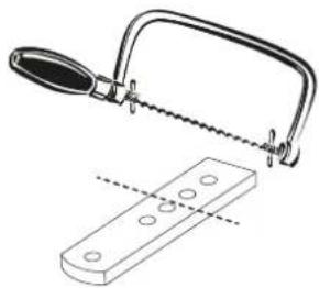
natural_image
Technical illustration of a hand saw cutting through a wooden plank (no text or symbols)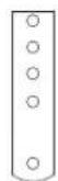
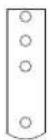
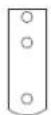
Fig. 3
| EKKO 300A (EAM8) | |
| A (mm) B (mm) | |
| 110° 100 100 | |
| 110° 120 120 | |
| 105° 130 130 | |
| 100° 140 140 | |
| 90° 150 150 | |
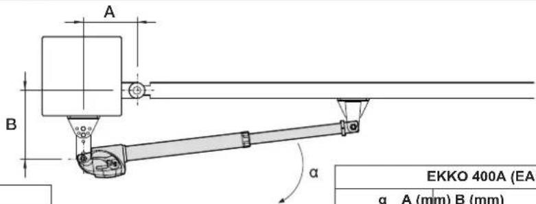
| EKKO 400A (EAM9) | ||
| α A (mm) B (mm) | ||
| 110° 120 120 | ||
| 110° 150 150 | ||
| 110° 170 170 | ||
| 105° 180 180 | ||
| 100° 190 190 | ||
| 90° 200 200 | ||
Fig. 4
natural_image
Technical illustration of a mechanical assembly with two blocks and mounting brackets (no text or symbols)Fig. 5
Fig. 6
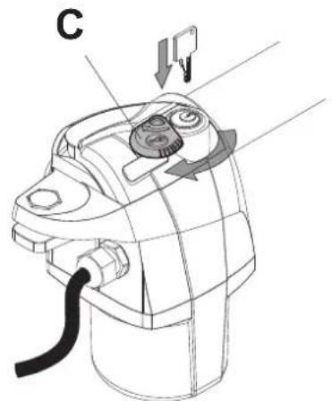
Fig. 7
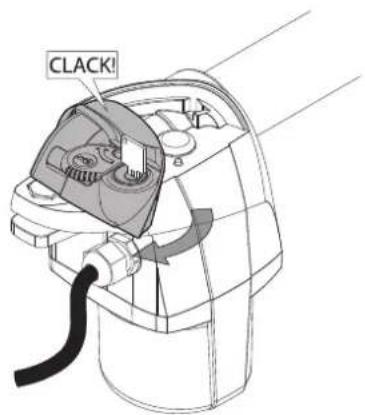
Fig. 8
Indice: ...... Pagina
| Product characteristics | 6 |
| Technical data | 6 |
| Limitations of use | 6 |
| Standard system set-up | 7 |
| Determination of the operator rotation pivot position | 7 |
| Installation of brackets and positioning of operator on the brackets | 7 |
| Operator release | 7 |
| Electrical connections | 7 |
| User manual | 8 |
The following safety information is an integral and essential part of the product and must be supplied to the user.
Read it carefully as it provides important guidelines regarding installation, use and maintenance. Always store this module carefully and transfer it to any subsequent users of the system. Incorrect installation or improper use of the product may constitute a serious hazard.
SAFETY INSTRUCTIONS FOR INSTALLERS
- Carefully read the instructions on this leaflet: they give important information on the safety, use and maintenance of the installation.
- After removing the packing, check the integrity of the set. Packing components (plastic bags, expanded polystyrene etc.) are dangerous for children. Installation must be carried out according to national safety regulations.
- Before connecting the set, ensure that the data on the label correspond to those of the mains.
- This apparatus must only be used for the purpose for which it was expressly designed, e.g. for automation systems for gates, garage doors and road barriers. Any other use may be dangerous. The manufacturer is not responsible for damage caused by improper, erroneous or irrational use.
- Before cleaning or maintenance, disconnect the set.
- In the event of faults and/or malfunctions, disconnect from the power supply immediately by means of the switch and do not tamper with the apparatus.
- For repairs apply only to the technical assistance centre authorized by the manufacturer.
- Safety may be compromised if these instructions are disregarded.
- Installers must ensure that manuals with the above instructions are left on connected units after installation, for users' information.
- All items must only be used for the purposes designed.
- WARNING: to prevent injury, this apparatus must be securely attached to the wall in accordance with the installation instructions.
- This leaflet must always be enclosed with the equipment.
1. Product characteristics:
Linear 230 Vac operator with exterior mounting for residential and industrial swing gates with:
- aligned thrust
- customised key release and lever
-
weldable, boltable and adjustable fixing brackets
-
Technical data
| Description EAM8.L/EAM8.R EAM9.L/EAM9.R | ||
| Electric motor power supply 230 Vac 50/60 Hz | ||
| Electric motor maximum absorption 1.1 A | ||
| Electric motor maximum power 240 W | ||
| Maximum thrust 2800 N | ||
| Maximum gate leaf length 3 m 4 m | ||
| Maximum gate leaf weight (at maximum length) 200 kg | ||
| Maximum opening 110° | ||
| Opening time | min. 13sec. max 20 sec. | min. 16sec. max 27 sec. |
| Protection rating | IP54 | |
| Operating temperature | From -20 to +50°C | |
| Capacitor | 8 μF | |
| Dimensions | See fig. 2 | |
| Weight | 5.7 kg | 6 kg |
| Frequency of use 50% | ||
| Useful travel | 300 mm | 400 mm |
- Limitations of use:
| Length of gate leaf (metres) | Gate leaf weight (kg) EKKO 300A (EAM8) | Gate leaf weight (kg) EKKO 400A (EAM9) |
| 1.5 | 580 | - |
| 2 | 380 | - |
| 2.5 | 250 | 450 |
| 3 | 200 | 320 |
| 3.5 | - | 240 |
| 4 | - | 200 |
4. Standard system set-up:
Before installing the automation, check that:
- the gate hinges are sturdy and efficient and there is no strong friction
- the length of the gear motor power supply cables does not exceed 15 metres
- there are the mechanical stops which are properly secured
For the system wiring arrangements, refer to fig. 1
5. Determination of the operator rotation pivot position
To identify the correct positioning of the operator rotation pivot, refer to the table and relative heights "A" and "B" indicated in fig. 4 according to the required opening angle "α".
Check that the identified heights "A" and "B" are compatible with the gate positioning on the pillar.
Check particularly that in the closing position the operator does not touch the inside edge of the pillar, which could happen if there are large distances between the gate hinges and the inside edge of the pillar (height "Z").
Minor deviations from the sizes “A” and “B” recommended in the table in fig. 4 are possible, considering however that the greater the difference between “A” and “B” the less fluid the movement of the automated gate (strong accelerations of the gate leaf at the start of the movement or vice versa) with increased forces acting on the fixing brackets and the pillar.
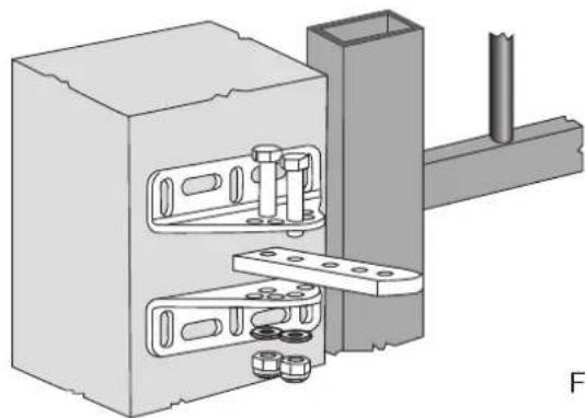
6. Installation of brackets and positioning of operator on the brackets:
Having identified the optimal heights "A" and "B" for installation, proceed to position the front and rear bracket.
The brackets may be welded or screwed to the pillar, and can therefore be installed on stone pillars using suitable heavy duty fixing plugs.
The rear bracket can be adjusted to different positions and can be cut to a shorter length as indicated in fig. 3.
Assemble and position the rear bracket as indicated in fig. 5.
Having positioned the rear bracket, close the gate so it comes into contact with the mechanical closing stop, fully extend the operator boom and then slide it in by 1 cm.
Now, by mounting the front bracket on the operator as indicated in fig. 6, positioning the operator in the horizontal position, the fixing position of the front bracket on the gate can be identified.
The front bracket can be either welded or bolted to the gate.
Important:
Check that the gate structure is sufficiently resistant in the front bracket fixing position to support the traction force of the operator. It is not possible for example to fix the front bracket to the vertical posts of the bracket, always fix the front bracket to a structural element of the gate leaf (such as a crossbeam).
Having fixed the front bracket to the gate, install the operator on the brackets using the bolts supplied.
7. Operator release:
Having installed the operator on the brackets, it can be released as indicated in fig. 7 and in fig. 8:
- open the flap "C" covering the release lock
- open the lock with the key supplied
- with the lock open, release the operator by turning the release lever "M" next to the lock
With the operator released, simulate a complete opening and closing manually, during the movement there must be no mechanical friction and the manual movement of the lead must be possible without any excessive force.
N.B.: Check for the presence and tightness of the mechanical stops on both opening and closing. Should the gate leaf exceed a length of 2 metres it is necessary to install the electrical lock.
To reset the operator, follow the procedure described above in the reverse order.
CAUTION: Unlock and reset with the gate and electric motor stationary, do not leave the release lock without a cover.
8. Electrical connection:
The operator is already fitted with an electrical wire connected to the motor.
The wire is 0.8 m long and must be connected in a specific junction box mounted on the pillar, if the control unit cannot be reached directly.
For wiring to the control unit, follow the diagram given in table:
| Wire colour Description | |
| Yellow-Green Earth connection | |
| Black Gear 1 (shaft withdrawal, gate opening with gate opening inwards) | |
| Brown Gear 2 (shaft extension, gate closing with gate opening inwards) | |
| Grey Motor common | |
User Manual
Model:
EKKO 300A (EAM8.R-EAM8.L)
EKKO 400A (EAM9.L-EAM9.R)
To release the operator and move it manually, proceed as described and illustrated in the following figures:
open the flap "C" covering the release lock (fig. A)
open the lock with the key supplied (fig. A)
with the lock open, release the operator by turning the release lever "M" next to the lock (fig. B)
To reset the operator, follow the procedure described above in the reverse order.
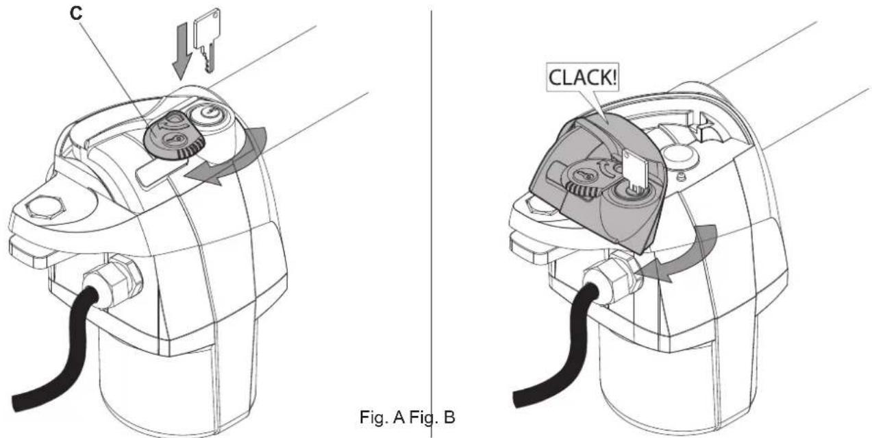
CAUTION: Unlock and reset with the gate and electric motor stationary, do not leave the release lock without a cover.
Maintenance:
Periodically check the fixing bolts, the integrity of the connecting cables, the correct functioning of the safety systems (photocells and sensitive edges), the robustness of the mechanical stops and the soundness of the systems for supporting the gate leaf (hinges or bearings). Every 2 years it is recommended to replace the batteries in the remote control.

Directive 2002/96/EC (WEEE)
The crossed-out wheelie bin symbol marked on the product indicates that at the end of its useful life, the product must be handled separately from household refuse and must therefore be assigned to a differentiated collection centre for electrical and electronic equipment or returned to the dealer upon purchase of a new, equivalent item of equipment.
The user is responsible for assigning the equipment, at the end of its life, to the appropriate collection facilities.
Suitable differentiated collection, for the purpose of subsequent recycling of decommissioned equipment and environmentally compatible treatment and disposal, helps prevent potential negative effects on health and the environment and promotes the recycling of the materials of which the product is made. For further details regarding the collection systems available, contact your local waste disposal service or the shop from which the equipment was purchased.
Risks connected to substances considered as dangerous (WEEE).
According to the WEEE Directive, substances since long usually used on electric and electronic appliances are considered dangerous for people and the environment. The adequate differentiated collection for the subsequent dispatch of the appliance for the recycling, treatment and dismantling (compatible with the environment) help to avoid possible negative effects on the environment and health and promote the recycling of material with which the product is compound.
Product is according to EC Directive 2004/108/EC and following norms.
CE
EC DECLARATION OF CONFORMITY
(Declaration of incorporation of partly completed machinery annex IIB 2006/42/EC)
No.: ZDT00585.00
The undersigned, representing the following manufacturer Vimar SpA
Viale Vicenza, 14 - 36063 Marostica (VI) Italy
herewith declares that the products
OPERATORS FOR GATES WITH SWING DOORS - SERIES EKKO
Articles
Trade mark Type ref. Cat. ref. Description
Elvox EAM8.L EAM8.L Non-reversible 230 V electromechanical linear left operator for swing gates up to 3 m and 200 kg, complete with adjustable mounting brackets
| Elvox | EAM9.L | EAM9.L | Idem, for swing gates up to 4 m and 200 kg |
| Elvox | EAM8.R | EAM8.R | Non-reversible 230 V electromechanical linear right operator for swing gates up to 3 m and 200 kg,complete with adjustable mounting brackets |
Elvox EAM9.R EAM9.R Idem, for swing gates up to 4 m and 200 kg
are in conformity with the provisions of the following EC directive(s) (including all applicable amendments) and that the following standards and/or technical specifications have been applied
Machinery Directive 2006/42/EC
LV Directive 2006/95/EC: EN 60335-2-103 (2003)
EMC Directive 2004/108/EC: EN 61000-6-3 (2007), EN 61000-6-2 (2005),
Further hereby declares that the product must not be put into service until the final machinery into which it is to be incorporated has been declared in conformity with the provisions of Directive 2006/42/EC, where appropriate.
Declares that the relevant technical documentation is compiled by Vimar SpA and in accordance with part B of Annex VII of Directive 2006/42/EC and the following essential requirements of this Directive are applied and fulfilled: 1.1.1, 1.1.2, 1.1.3, 1.1.5, 1.1.6, 1.2.1, 1.2.2, 1.2.6, 1.3.1, 1.3.2, 1.3.3, 1.3.4, 1.3.7, 1.3.8, 1.3.9, 1.4.1, 1.4.2, 1.5.1, 1.5.2, 1.5.4, 1.5.5, 1.5.6, 1.5.7, 1.5.8, 1.5.9, 1.6.1, 1.6.2, 1.7.1, 1.7.2, 1.7.3, 1.7.4
I undertake to make available, in response to a reasoned request by the national authorities, any further supporting product documents they require.
Marostica, 24/02/2015
The Managing Director
Note: The contents of this declaration correspond to what declared in the last revision of the official declaration available before printing this manual. The text herein has been re-edited for editorial purposes. A copy of the original declaration can be requested to Vimar SpA
Index Page
DÉCLARATION DE CONFORMITÉ
Directive machines 2006/42/CE
Directive BT 2006/95/CE : EN 60335-2-103 (2003)
Directive EMC 2004/108/CE : EN 61000-6-3 (2007), EN 61000-6-2 (2005),


- Legende
- SAFETY INSTRUCTIONS FOR INSTALLERS
- Product characteristics:
- Standard system set-up:
- Determination of the operator rotation pivot position
- Installation of brackets and positioning of operator on the brackets:
- Important:
- Operator release:
- Electrical connection:
- User Manual
- Maintenance:
- EC DECLARATION OF CONFORMITY
- OPERATORS FOR GATES WITH SWING DOORS - SERIES EKKO
- Articles
- DÉCLARATION DE CONFORMITÉ
Brand : Vimar
Model : ELVOX EAM9.L
Category : Gate automation