
ELVOX ESM6.D - Gate automation Vimar - Free user manual and instructions
Find the device manual for free ELVOX ESM6.D Vimar in PDF.

| Product type | Control unit for sliding gearmotor 230 Vac |
| Brand | Vimar (Elvox range) |
| Model | ELVOX ESM6.D (RS10 series) |
| Power supply | 230 Vac (50/60 Hz) |
| Max motor power | 600 W |
| Motor protection fuse | F2 (5x20) 5 A |
| Logic protection fuse | F1 (5x20) 630 mA |
| Flashing light output | 230 Vac, max 40 W |
| 24 Vdc accessory output | 24 Vdc, max 300 mA |
| Built-in radio receiver | Yes, capacity 128 remote controls (fixed or rolling code) |
| Encoder | Built-in (obstacle detection and speed control) |
| Display | Programming screen |
| Safety inputs | STOP, FOTO, STPA (normally closed) |
| Command inputs | APRI (open only), APCH (sequential), APED (pedestrians) |
| Limit switches | FCAP (open), FCCH (close), normally closed |
| Programmable functions | Automatic closing, slowdown, motor force, obstacle detection, etc. |
| Fault memory | History of last 9 errors |
| Operating temperature | -20 °C to +55 °C (standard estimate) |
| Protection rating | IP54 (estimate for outdoor use) |
| Dimensions (approx.) | 150 x 100 x 50 mm (estimate) |
| Weight (approx.) | 0.5 kg (estimate) |
| Maintenance | Check diagnostic LEDs, keep connections clean |
Frequently Asked Questions - ELVOX ESM6.D Vimar
User questions about ELVOX ESM6.D Vimar
0 question about this device. Answer the ones you know or ask your own.
Ask a new question about this device
Download the instructions for your Gate automation in PDF format for free! Find your manual ELVOX ESM6.D - Vimar and take your electronic device back in hand. On this page are published all the documents necessary for the use of your device. ELVOX ESM6.D by Vimar.
USER MANUAL ELVOX ESM6.D Vimar
Board with 230 Vac display for sliding gate
flowchart
graph TD
    A["CN1 CN2"] -->|9 10 11 12| B["COM"]
    A -->|-| C["FOTO"]
    A -->|+| D["STPA"]
    E["RX1"] --> F["COM"]
    G["RX2"] --> H["FOTO"]
    I["TX1TX2"] --> J["COM"]
    K["STPA"] --> L["FOTO"]
    M["COM"] --> N["STPA"]
    O["STPA"] --> P["FOTO"]
    Q["COM"] --> R["STPA"]
    S["STPA"] --> T["FOTO"]
    U["COM"] --> V["STPA"]
    W["STPA"] --> X["FOTO"]
    Y["COM"] --> Z["STPA"]
    style A fill:#f9f,stroke:#333
    style E fill:#ccf,stroke:#333
    style G fill:#ccf,stroke:#333
    style I fill:#ccf,stroke:#333
    style M fill:#ccf,stroke:#333
    style Q fill:#ccf,stroke:#333
    style U fill:#ccf,stroke:#333
    style W fill:#ccf,stroke:#333
    style X fill:#ccf,stroke:#333
    style Y fill:#ccf,stroke:#333
    style Z fill:#ccf,stroke:#333
Fig. 11
natural_image
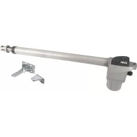
Technical diagram showing two electrical components connected by wires, one with a 24-pin connector and the other a pole-mounted device (no text or symbols present)Fig. 13
1 - Characteristics....15
2 - Description of the control unit....15
3 - Electrical wiring harnesses 16
4 - Description of the LEDs in the circuit 20
5 - Description of the buttons in the circuit 20
6 - Full description of the programming menu....21
7 - Error messages ....26
8 - Troubleshooting 26
RS10
1 - Characteristics
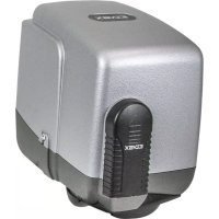
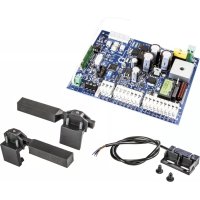
Control panel for governing sliding gear motors, 230V ac with 600W maximum power, equipped with inputs for limit switch, encoder (used for obstacle detection and speed control) integrated receiver and display interface. The control unit enables:
- customizing the space and speed of deceleration in both opening and closing phases
- equipped with an obstacle detection system (if there is an encoder circuit)
- LED for input diagnostics
- removable data memory
- integrated receiver with capacity for 128 remote control codes (hard coded or rolling code)
- log of the last 9 faults or errors
2 - Description of the control unit
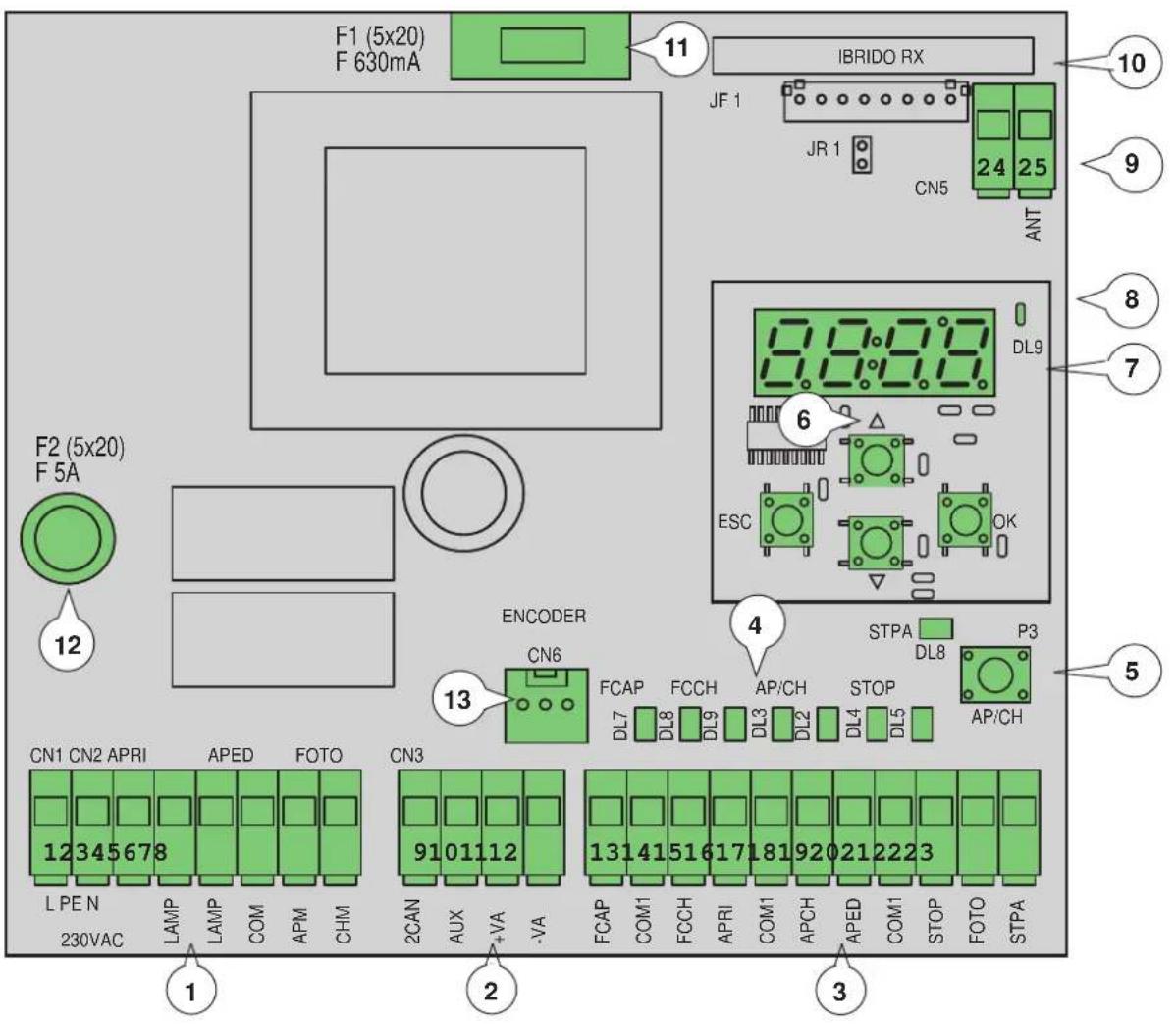
Fig. 1
Key:
1 - Removable terminal for the power line, flashing light and electric motor
2 - Removable terminal for 24 V d.c. outputs
3 - Removable terminal for safety and control inputs
4 - LED for input diagnostics
5 - Control sequential button
6 - Buttons for menu scrolling
7 - Programming display
8 - LED for signalling faults
9 - Removable aerial connector
10 - Radio module
11 - Protection fuse for 24V output and control logic (630mA)
12 - Protection fuse for motor output, transformer and flashing light (5A)
13 - Encoder connector
RS10
3 - Electrical wiring harnesses
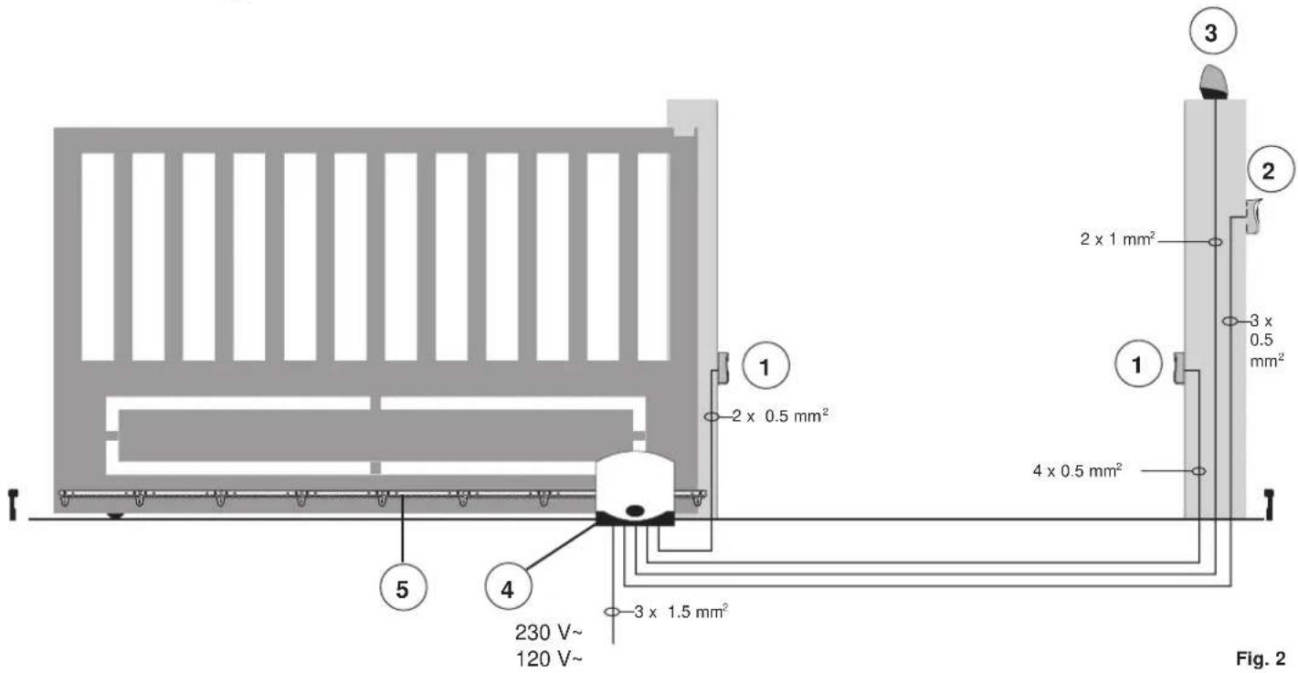
Key:
1 - Photocells
2 - Selector switch
3 - Flashing light
4 - Gear motor
5 - Rack
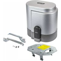
The control unit can work with or without an encoder. When switching on, the control unit checks for the presence of the encoder on connector CN6. For operation without an encoder it is necessary to insert the jumper in connector CN6 as shown in the image fig.3 and power up the control unit. With this configuration, the obstacle detection function and parameter P16 are not active. For operation with an encoder, it is necessary to insert the cable of the encoder circuit in the connector CN6 and power the control unit.
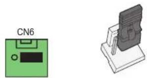
natural_image
Two electronic components: a green device labeled CN6 and a gray device with a shield-like cover (no text or symbols on the devices themselves)Fig. 3
3.1 - Wiring for power line, flashing light and electric motor:

RS10
3.2 - Wiring for 24V outputs:

Fig. 5
| Number | Description Function | |
| 1-2-3 | Power supply line | Power line 230 V ac (1 = phase / 2 = ground wire / 3= neutral) |
| 4-5 | Output for flashing light | Output for flashing light (230 V a.c. max 40 W) |
| 6-7-8 Output for powering the electric motor | Output powering the motor (6 = common / 7 = opens / 8 = closes) the capacitor is connected in terminal 7 and 8 in parallel with the electric motor | |
| 9-11 | Second radio channel or photo-test output | Second radio channel or photo-test output (selectable with parameter P08, max. 65 mA) |
| 10-11 | Gate movement warning output | Gate movement warning output (selectable with parameter P07, max. 65 mA) |
| 11-12 | 24Vdc output to power accessories | 24 V dc output to power photocells and accessories (11 = GND / 12 = +24 Vdc max 300 mA) |
3.3 - Input wiring
The control panel is supplied with non-jumpered normally closed safety inputs (STOP, FOTO, STPA), add a jumper between the common (COM) and input you do not intend to use.
3.3.1 - Connecting control buttons and key switch
Normally open contacts (the red AP/CH or APED LEDS light up when the selector or buttons connected in parallel are operated):
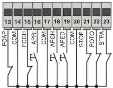
Fig. 6
| Terminal number | Description Input type | |
| 14-17-20 | COM: Control inputs common (permanent GND) | - |
| 13 | FCAP: Opening limit switch Input if the gate opens to the right (P18 = R), closing limit switch input if the gate opens to the left (P18 = L) | Normally closed |
| 15 | FCCH: Closing limit switch Input if the gate opens to the right (P18 = R), opening limit switch input if the gate opens to the left (P18 = L) | Normally closed |
| 16 | OPEN: Opening-only button input, dedicated for timer or detector for magnetic induction coils | Normally open |
| 18 | APCH: Sequential control input, to govern the complete travel of the gate | Normally open |
| 19 | APED: Sequential control input, to govern the pedestrian travel of the gate | Normally open |
| 21 | STOP: Input for stopping the gate | Normally closed |
| 22 | PHOTO: Photocell input, active during gate closing | Normally closed |
| 23 | STPA: Input for edges or internal photocell, active during gate closing and opening | Normally closed |
RS10
3.4 - Connecting control buttons and key switch
normally open contacts (the APCH or aped LEDs come on when the selector or the buttons connected in parallel are operated) the APCH input controls opening or closing the gate completely, the APED input controls partial gate opening or closing:
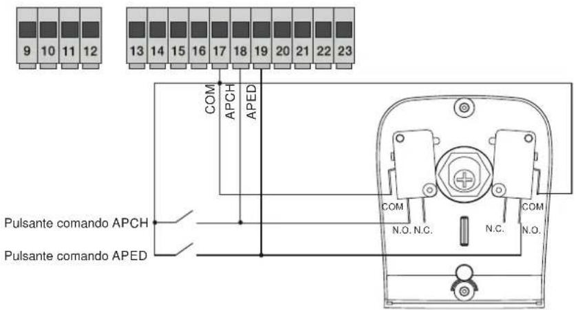
Fig. 7
3.5 - Connection of timer or detector with magnetic induction
with normally open contact (the open LED comes on when the timer or magnetic induction detector are operated) the OPEN input commands full opening of the gate, until the contact is closed, the gate opens and remains in the open position, the APCH, APED commands and saved remote controls are not active until the contact is reset from closed to open, after the automatic closing time set with the PAUSE trimmer, the gate closes, this input is used to open and hold open the gate at the times of greatest influx:
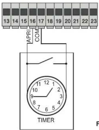
Fig. 8
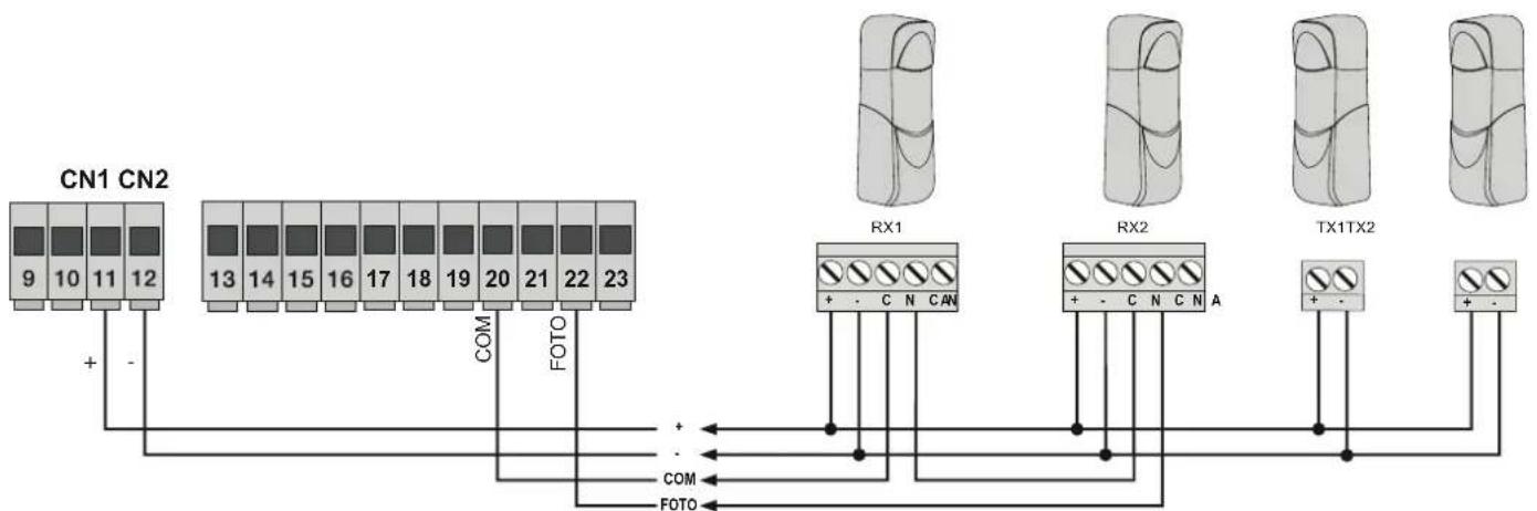
3.6 - Connecting photocells
Normally closed contact (when the photocells are not engaged the PHOTO LED must be on), when this input trips during closing it reverses the movement, if not used then jumper between COM. and PHOTO, you must observe the polarity of the power supply for the photocells:
flowchart
graph TD
    A["CN1 CN2"] -->|+ -| B["RX1"]
    A -->|- | C["RX2"]
    A -->|COM| D["TX1TX2"]
    A -->|FOTO| E["FOTO"]
    B --> F["+ - C N CAN"]
    C --> G["+ - C N C N A"]
    D --> H["+ -"]
    E --> I["+ -"]
Fig. 9
RS10
3.7 - Sensitive edge connection
Programmable input (with edge or photocell not engaged the STPA LED must be ON). if this input trips during opening it immediately reverses the movement for 1.5 seconds and then stops the gate, while during closure it reverses the movement until fully open, see the parameter P06 to select the type of edge. If not used, jumper between COM. and STPA and set the parameter P06 OFF.
Switch edge connection Relative sensitive edge connection
STPA input as edge with electromechanical switch, set parameter P06 OFF.
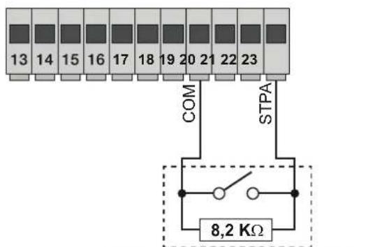
STPA input as resistive edge at 8.2Kohm, set parameter P06 ON
Fig. 10
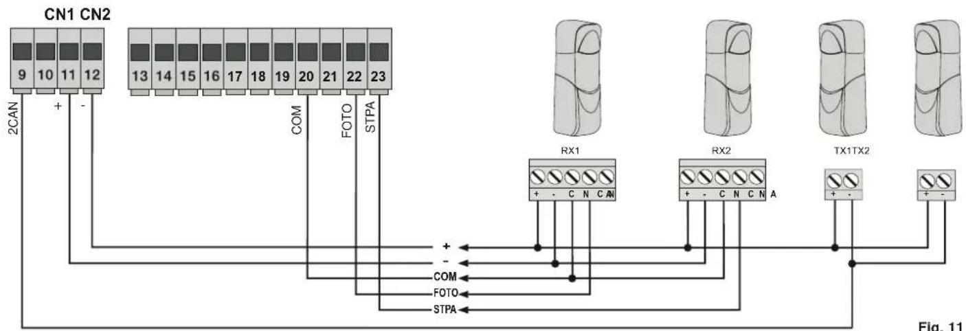
3.8 - Electrical connection with photo-test function active:
with parameter P08 on 1, the control unit governs the operation of the photocells connected on the PHOTO input, with parameter P08 on 2 the control unit governs the operation of the photocells connected on the STPA input, with parameter P08 on 3 the control unit governs the operation of the photocells connected on the PHOTO and STPA inputs. Figure 10 shows an example of a connection with photo-test on only for the PHOTO input.
flowchart
graph TD
    A["CN1 CN2"] -->|9 10 11 12| B["COM"]
    A -->|-| C["FOTO"]
    A -->|+| D["STPA"]
    E["2CAN"] --> A
    F["RX1"] --> G["COM"]
    F --> H["FOTO"]
    F --> I["STPA"]
    J["RX2"] --> K["COM"]
    J --> L["FOTO"]
    J --> M["STPA"]
    N["TX1TX2"] --> O["COM"]
    N --> P["FOTO"]
    N --> Q["STPA"]
    R["+"] --> F
    S["-"] --> F
    T["+"] --> F
    U["-"] --> F
    V["+"] --> W["FOTO"]
    X["+"] --> Y["STPA"]
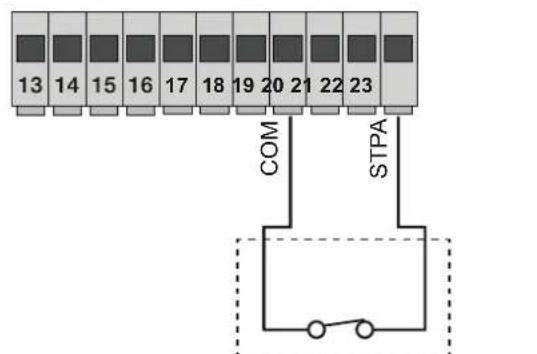
3.9 - Stop button connection:
Normally closed contact, opening the contact causes the gate to stop and suspends the automatic closing time (when the button is not engaged, the STOP LED should be lit), if not used then jumper between COM and STOP:
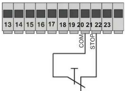
Normally closed button
Fig. 12
RS10
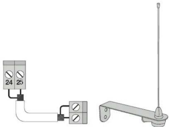
3.10 - Connecting the aerial:
The 17 cm rod is supplied pre-wired, to increase the range connect the aerial, as shown in the figure:
natural_image
Pure electrical circuit lines without any symbolsFig. 13
4 - Description of the LEDS in the circuit
| Abbreviation Colour LED status Terminal status | ||
| OPEN Red | Off APRI input (terminal 16) not engaged | |
| On APRI input (terminal 16) engaged | ||
| APCH Red | Off APCH input (terminal 18) not engaged | |
| On APCH input (terminal 18) engaged | ||
| APED Red | Off APED input (terminal 19) not engaged | |
| On APED input (terminal 19) engaged | ||
| STOP Green | Off STOP input (terminal 21) engaged | |
| On STOP input (terminal 21) not engaged, if not used then jumper between COM and STOP terminals | ||
| PHOTO Green | Off PHOTO input (terminal 22) engaged (photocell beam interrupted) | |
| On | ||
| PHOTO input (terminal 22) not engaged, if not used then jumper between COM and PHOTO terminals | ||
| STPA Green | Off STPA input (terminal 23) engaged (sensitive edge pressed) | |
| On | ||
| STPA input (terminal 23) not engaged, if not used then jumper between COM and PHOTO terminals | ||
| FCAP Green | Off | |
| FCAP input (terminal 13) engaged. The gate is in the position of:Opening limit switch if parameter P18 = R (opening to right)Closing limit switch if parameter P18 = L (opening to left) | ||
| On FCAP input (terminal 13) not engaged. | ||
| FCCH Green | Off | |
| FCCH input (terminal 15) engaged. The gate is in the position of:Closing limit switch if parameter P18 = R (opening to right)Opening limit switch if parameter P18 = L (opening to left) | ||
| On FCAP input (terminal 15) not engaged. | ||
| DL1 Red Fast blink Flashes quickly if one of the inputs is engaged | ||
5 - Description of the buttons in the circuit
| Abbreviation | Description |
| AP/CH | Controls opening and closing the gate |
| ESC Exit or go | back to the lower level of the menu |
| ▲ UP | Increases the displayed value by one unit or scrolling on the same menu level |
| ▼ DOWN | Decreases the displayed value by one unit or scrolling on the same menu level |
| OK | Confirms the value or moves to the top level of the menu |
Preliminary check:
After powering up the control unit, the display shows the name of the control unit RS10, the firmware version Fxxx and then switches off. Check the diagnostic LEDs of the inputs, the STOP, PHOTO, STPA, FCAP and FCCH LEDs must be on (if the limit switches are not engaged).
RS10
FOR OPERATION WITH A MAINS FREQUENCY OF 60 HZ FOLLOW THE INSTRUCTIONS:
- disconnect the power supply to the control unit
- press the UP and DOWN buttons simultaneously
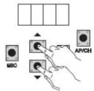
- power up while keeping the buttons pressed until the display shows 60 H
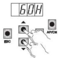
To return the control unit to operate at 50 Hz repeat the procedure, the display will show 50 H.
6 - Full description of the programming menu
The programming menu is divided into 3 levels: first the main level, second the parameters level and third the values level
Main menu:
| Display Message Description |
| LRNE Learning travel with quick programming (see section 7) |
| RAD Remote control management |
| LRN Learning travel with custom programming |
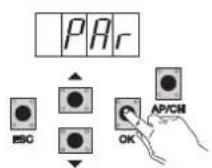
| PAR Used to modify all the parameters of the control panel |
| DEF Used to return to the default values of the parameters menu |
| CNT Used to view the manoeuvres carried out |
| PASS Used to enter a 4-digit password |
After selecting the desired item from the main menu by pressing the UP or DOWN button, confirm by pressing OK.
6.1 - LRNE: quick procedure for programming gate travel
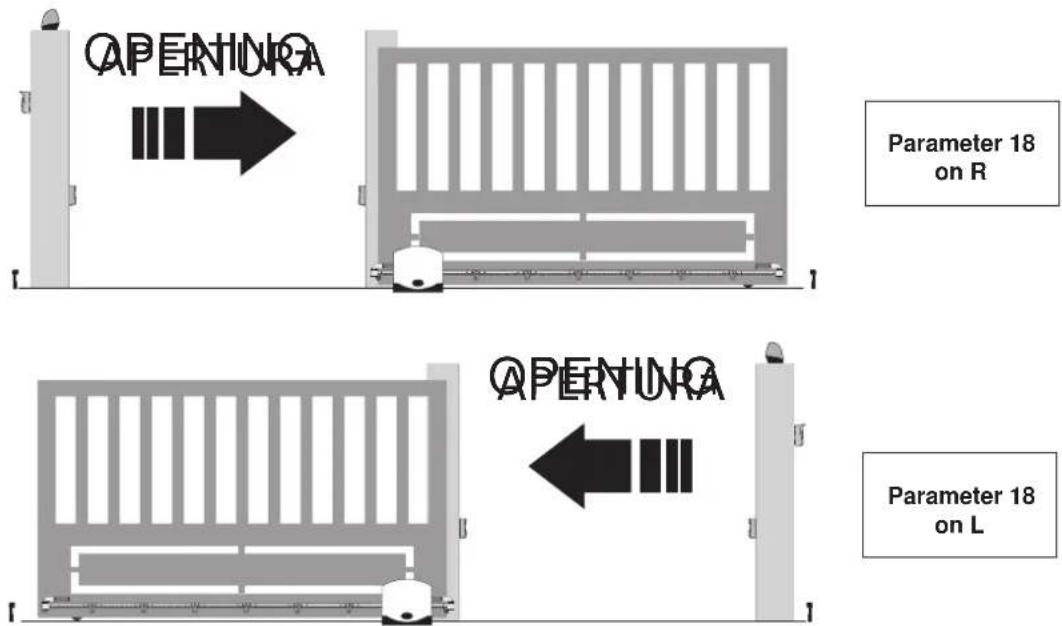
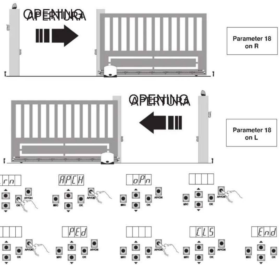
N.B.: Before you start programming, check parameter 18 (opening direction)
If the gate opens to the right, set parameter 18 (opening direction) to R.
If the gate opens to the left, set parameter 18 (opening direction) to L
RS10
Even with the gate not closed, after entering programming mode by pressing UP, OK, and AP/CH, the gate starts opening until the limit switch is engaged. After 2 seconds the gate starts closing at cycle speed, slows down and continues until the closing limit switch is engaged. The control panel saves the gate travel (the deceleration speed and distance are set as by default).
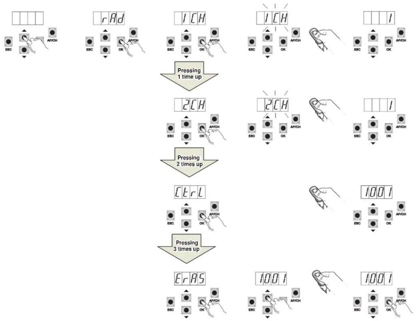
6.2 - RAD: remote control management menu is divided into 4 parameters
flowchart
graph TD
    A["1 CH"] --> B["Pressing 1 time up"]
    C["1 CH"] --> D["Pressing 2 times up"]
    E["2 CH"] --> F["Pressing 3 times up"]
    G["3 CR L"] --> H["Pressing 3 times up"]
    I["1001"] --> J["Output meters"]
    K["1001"] --> L["Output meters"]
RS10
| Display Message Description Display message after activating the remote control | ||
| 1 CH | Used to save the remote control button corresponding to the input APCH | (memory location occupied by the remote control just saved) |
| 2 CH | Used to save the remote control button corresponding to the input PED or output 2CAN | (memory location occupied by the remote control just saved) |
| CTRL | Pressing the button on the remote control lets you compare and see the memory location where it has been saved. | First character of the display:- channel associated with the saved remote control button (1 or 2)Last three characters of the display:- memory location occupied by the remote control just saved |
| ERAS | Used to delete a remote control in the memory list or all the remote controls in the memory. | 1. Press OK until ALL appears on the display. Release OK To delete all the remote controls:- press and hold OK until oooo appears on the displayTo delete a single remote control:- scroll with the UP or DOWN buttons until the memory location occupied by the remote control which you want to delete, press and hold OK until the display shows oooo (deleting a remote control from the memory position clears the associations of both the first and the second channel) |
N.B. The first saved remote control configures the control panel to accept only remote controls with a rolling code or only remote controls with a fixed 12-bit code.
Note: It is advisable to fill in the final table indicating the number of the memory cell (it is displayed while saving the remote control) in the user name, this enables deleting a remote control should it get lost.
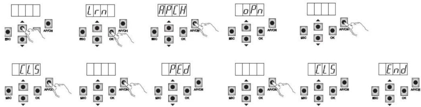
6.3 - LRN: Learning travel with custom programming lets you define the points for starting deceleration when both opening and closing
N.B.: Before you start programming, check parameter 18 (opening direction)
If the gate opens to the right, set parameter 18 (opening direction) to R.
If the gate opens to the left, set parameter 18 (opening direction) to L
RS10
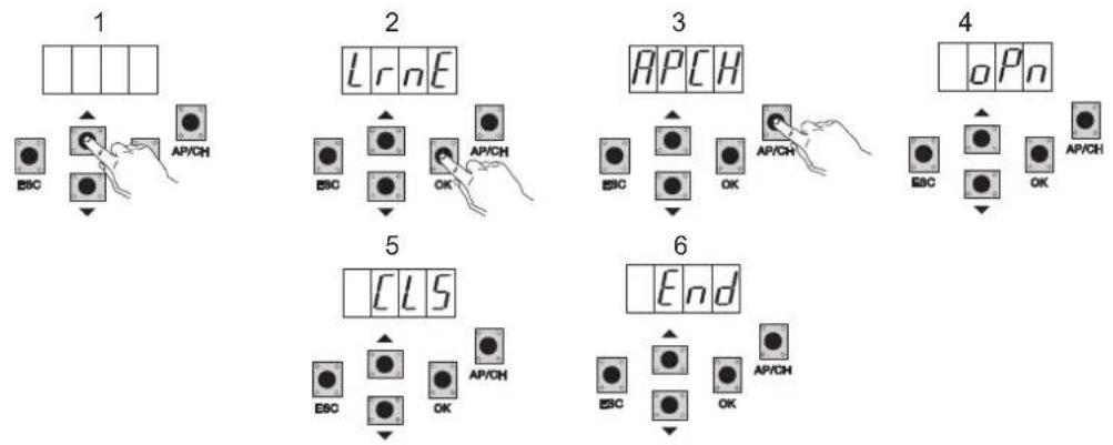
- even with the gate not closed, press the OK button to enter advanced travel programming mode, the display will indicate APCH
- press and release the AP/CH button, the gate closes if it is not in the closed position; once it reaches the closing limit switch (closing limit switch engaged, FCCH LED off), the display indicates the OPN message and the gate opens
- press and release the AP/CH button to determine the starting point of deceleration on opening
- the gate continues slowing down until the opening limit switch trips (the FCAP LED goes out), the display indicates the CLS message and the gate starts to close
- press and release the AP/CH button to determine the starting point of deceleration on closing
- the gate continues slowing down until the closing limit switch trips (the FCCH LED goes out)
- the display indicates the PED message and the gate opens
- press and release the AP/CH button to determine the pedestrian opening distance
- the gate continues until the closing limit switch trips (the FCCH LED goes out) the display reads END, the travel has been saved correctly.
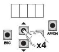
6.4 - PAR: Used to modify all the parameters of the control unit, press the OK button to display the list of parameters, the display will show P01 (parameter number 1), the UP or DOWN button lets you scroll through the list of parameters (see parameter table).
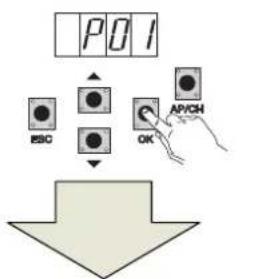
flowchart
graph TD
    A["POI"] --> B["ESO"]
    A --> C["OK"]
    A --> D["AP/CH"]
    B --> E["Down Arrow"]
    C --> E
    D --> E
Press the pushbutton until the parameter to change
Parameter table
| Parameter number | Description Settable values | Default value | Modified value | |
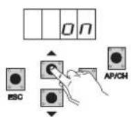
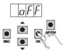
| P01 Enables automatic closing ON/OFF OFF | ||||
| P02 Sets the automatic closing time 2-600 seconds | 60 seconds | |||
| P03 APCH input operation | 1= when opening, APCH input not active (condo)2 = APCH as sequential (open, stop, close, open)3 = APCH as sequential (open, close, open...)4 = APCH commands only opening, APED commands only closing | 1 | ||
| P04 Pre-flash | OFF= pre-flash offON= pre-flash on (flashing output activated for 3 seconds before the movement of the gate) | ON | ||
| P05 Instant closure | ON= with the gate opening or open on disengaging the PHOTO input (terminal 22) the gate closes 3 sec. after completing openingOFF= normal operation | OFF | ||
| P06 Logic of the STPA input | 0= microswitch sensitive edge (the operation of this input immediately reverses the movement for 1.5 seconds and then stops the gate1= resistive sensitive edge (balanced with 8.2Kohm resistance), the operation of this input immediately reverses the movement for 1.5 seconds and then stops the gate2= photocell as internal protection (if engaged it stops the gate, until it is disengaged, then it continues opening) | 0 | ||
| P07 AUX output operating mode | OFF = flashes slowly during gate opening and is on steady when the gate is open and stationary, flashes rapidly during closing and is off when the gate is closed and stationaryON = flashes while the gate is moving and is off when the gate is stationary | OFF | ||
| P08 | Enables checking the safety inputs | 0 = input check off1= check only on PHOTO input2= check only on STPA input3 = check on PHOTO and STPA inputs | 0 | |
RS10
| P09 Slowdown | distance when closing | From 0 to 100%0%= no slowdown when closing100%= slowdown for the whole closing distance | 30% | |
| P10 | Slowdown distance when opening | From 100 to 0%100%= no slowdown when opening0%= slowdown for the whole opening distance | 70% | |
| P13 Opening deceleration speed | From 0 to 100%0%= minimum slowdown speed100%= maximum slowdown speed | 45% | ||
| P14 Closing deceleration speed | From 0 to 100%0%= minimum slowdown speed100%= maximum slowdown speed | 45% | ||
| P15 Motor force | From 0 to 100%0%= minimum force100%= maximum force | 50% | ||
| P16 | Force on obstacle detection(parameter can only be used with encoder) | From 0 to 100%0%= minimum force (maximum obstacle sensitivity)100%= maximum force (minimum obstacle sensitivity) | 50% | |
| P17 Braking | From 0 to 250= minimum braking force25= maximum braking force | 5% | ||
| P18 Gate opening direction | L= gate opening to the leftR= gate opening to the right | L | ||
| P20 | Selects the operation of the second radio channel | 2CAN= activates the 2CH outputPEDO = controls pedestrian opening while the 2CAN output functions as a courtesy light timed at 60 seconds | PEDO | |
| P21 Channel 2 | output activation time From 1 to 60 seconds 1 sec. | |||
| P22 | Pedestrian opening distance | From 0 to 100% of total gate travel | 50% | |
| P24 Break-out | on starting | OFF= gate starts with the force regulated with parameter P15ON= gate starts for 1 second at maximum power to then return to the force regulated with parameter P15 | ON | |
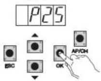
| P25 | Manned, APCH controls opening by keeping the button pressed,PED controls closing by keeping the button pressed | OFF: function disabledON: function active if the safety devices are open (PHOTO and STPA)gate starting is delayed by 3 seconds from actuating the button | OFF | |
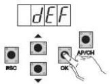
6.5 - DEF: Used to take the control unit to the default parameters, press and release the OK button until the display shows 4 dots to confirm the operation.
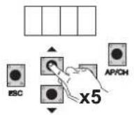
6.6 - CNT: used to view the number of openings followed by the gearmotor, the first counter A displays the number of absolute operations, the second counter P displays the operations performed after a reset controlled by the installer. This is shown in the following example:
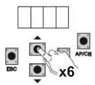
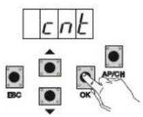
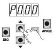
Pressing the UP button 6 times displays CNT (counter)
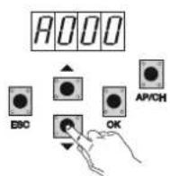
Press the OK button, the display shows the letter A (absolute counter cannot be reset) the number that follows should be multiplied by 10000
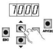
Press the UP button, the display shows the number to be added to get the total openings performed by the motor: absolute number =
(000*10000)+(7000)=7000
Press the UP button, the display shows the letter P (partial counter can be reset) the number that follows should be multiplied by 1000
Press the UP button, the display shows the number to be added to get the openings after resetting the partial counter: partial number =
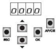
(000*10000)+(1000)= 1000, this means that it was reset on 6000 openings. To reset the partial counter, press and hold the OK button for at least 5 seconds until the display shows 0000 to confirm the operation.
RS10
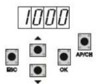
6.7 - PASSWORD: it is possible to enable a password on 3 levels, with level 1 the password is required to enter the PAR, DEF, LRNE and LRN menu, with level 2 the password is required to enter the RAD menu, with level 3 the password is required to enter all the menu items (LRNE, LRN, DEF, RAD, CNT, PAR, ERR).
N.B.: If you forget the password, you need to call the support centre
Example of entering password 4-3-2-1 at the second level:
A password is required every time you try to access the main menu (on pressing the Up or Down button the display will show PASS, you need to enter the password to display the main menu).
If a password of level 1 or 2 is entered, when you select the protected menu item you will be prompted for the password, enter the password and confirm with OK, if you exit the menu you will be prompted for the password.
If the password is incorrect the display will show NO.
7 - Error messages
| Message Description |
| F02 Detected an obstacle during the opening movement |
| F03 Detected an obstacle during the closing movement |
| F04 PHOTO input contact open |
| F06 STPA input contact open |
| F09 Maximum opening or closing time elapsed |
| F11 PHOTO input test failed |
| F12 STPA input test failed |
8 - Troubleshooting
| Problem Cause Solution | ||
| Automation does not work No mains supply | Blown fusesControl and safety inputs not working | Check the power line switchReplace the fuses with others of the same valueCheck the diagnosis LEDs (STOP, STPA and PHOTO must be on) |
| You cannot save the remote controls Batteries of the remote control discharged | Remote control not compatible with the first one savedReached memory saturation | Replace the batteriesThe first saved remote control configures the control unit to save only rolling-code remote controls or only dip-switch remote controlsDelete at least one remote control or add an external receiver (maximum capacity 128 remote controls) |
| You cannot enter travel programming | Safety devices open Check the diagnosis LEDs (STOP, STPA and PHOTO must be on) | |
| As soon as the gate starts it stops and reverses | Low acceleration on startingEncoder not detected | Increase parameter 15 and 16 (motor force and force on obstacle) and set parameter 24 On (break-out on starting)Check the encoder connector is properly inserted or if there is no encoder insert the jumper in connector CN6 (the control unit is configured to operate with or without the encoder when programming the travel) |
| During slowdown, the gate stops and reverses | Slowdown speed too low Increase parameter | 13 and 14 (slowdown speed on opening and closing) |
| The gate stops a few centimetres after the limit switch has tripped | High inertia Increase the value of parameter | 17 (braking power) |
EC DECLARATION OF CONFORMITY
(Declaration of incorporation of partly completed machinery Annex IIB Directive 2006/42/EC)
No.: ZDT00438.00
The undersigned, representing the following manufacturer Elvox SpA
Via Pontarola, 14/A - 35011 Campodarsego
(PD) Italy
herewith declares that the products
CONTROL BOARD - RS SERIES
Articles
RS09, RS10, RS11, RS15
are in conformity with the provisions of the following EU Directive(s) (including all applicable amendments) and that all of the following standards and/or specifications have been applied
LV Directive 2006/95/EC: EN 60335-2-103 (2003) + A11 (2009)
EMC Directive 2004/108/EC: EN 61000-6-1 (2007), EN 61000-6-3 (2007) + A1 (2011)
EN 61000-6-2 (2005), EN 61000-6-4 (2007) + A1 (2011)
R&TTE Directive 1999/5/EC: EN 301 489-3 (2002), EN 300 220-3 (2000)
Machinery Directive 2006/42/EC EN 13241 (2003) + A1 (2011), EN 12453 (2000)
He also declares that the product must not be commissioned until the end machine, in which it is to be incorporated, has been declared in conformity, when applicable, with the provisions of Directive 2006/42/EC.
He declares that the relevant technical documentation has been constituted by Elvox SpA, drawn up in accordance with Annex VIIB of Directive 2006/42/EC and that the following essential requirements have been fulfilled: 1.1.1, 1.1.2, 1.1.3, 1.1.5, 1.1.6, 1.2.1, 1.2.2, 1.2.6, 1.3.1, 1.3.2, 1.3.3, 1.3.4, 1.3.7, 1.3.8, 1.3.9, 1.4.1, 1.4.2, 1.5.1, 1.5.2, 1.5.4, 1.5.5, 1.5.6, 1.5.7, 1.5.8, 1.5.9, 1.6.1., 1.6.2, 1.7.1, 1.7.2, 1.7.3, 1.7.4.
He undertakes, in response to an adequately justified request from the national authorities, to present all the necessary supporting documentation concerning the product.
Campodarsego, 29/04/2013
The Chief Executive Officer
Note: The contents of this declaration match what was declared in the latest revision of the official declaration that was available before this manual was printed. This text has been adapted for editorial purposes. A copy of the original declaration can be requested from Elvox SpA.
RS10
Index Page
natural_image
Pure electrical circuit lines without any symbolsFig. 13
DÉCLARATION DE CONFORMITÉ
natural_image
Two electronic components: a green device labeled CN6 and a black-and-white photo of a clip or holder (no text or symbols on the devices themselves)Fig. 3
natural_image
Pure electrical circuit lines without any symbolsFig. 13
natural_image
Pure electrical circuit lines without any symbolsnatural_image
Pure electrical circuit lines without any symbolsEik. 13

- RS10
- - Characteristics
- Key:
- - Electrical wiring harnesses
- - Wiring for power line, flashing light and electric motor:
- - Wiring for 24V outputs:
- - Input wiring
- - Connecting control buttons and key switch
- - Connecting control buttons and key switch
- - Connection of timer or detector with magnetic induction
- - Connecting photocells
- - Sensitive edge connection
- - Electrical connection with photo-test function active:
- - Stop button connection:
- - Connecting the aerial:
- Preliminary check:
- FOR OPERATION WITH A MAINS FREQUENCY OF 60 HZ FOLLOW THE INSTRUCTIONS:
- - Full description of the programming menu
- - LRNE: quick procedure for programming gate travel
- - RAD: remote control management menu is divided into 4 parameters
- EC DECLARATION OF CONFORMITY
- CONTROL BOARD - RS SERIES
- Index Page
- DÉCLARATION DE CONFORMITÉ
Brand : Vimar
Model : ELVOX ESM6.D
Category : Gate automation